Patent application title: Managing Electric Energy Distribution To Multiple Loads Using Selective Capping
Inventors:
Daniel Humphrey (Houston, TX, US)
Daniel Humphrey (Houston, TX, US)
Mohamed Amin Bemat (Cypress, TX, US)
Mohamed Amin Bemat (Cypress, TX, US)
IPC8 Class: AG06F126FI
USPC Class:
700297
Class name: Specific application, apparatus or process electrical power generation or distribution system power supply regulation operation
Publication date: 2012-11-08
Patent application number: 20120283892
Abstract:
An electric energy distribution system may include plural loads
configured to receive electric energy from a common feed or branch. Each
of the loads may be configured to operate in at least first and second
modes such that it may consume current, VA or power up to a first cap
when running in its first mode and up to a second cap when running in its
second mode. The first cap may be higher than the second cap. A sensor
component may monitor a parameter that corresponds to an aggregate amount
of electric energy being consumed by all of the plural loads from the
common feed or branch. A manager component may be configured, when the
parameter meets or exceeds the threshold, to select one of the loads
currently running in its first mode and to cause the selected load to run
in its second mode.Claims:
1. A method for managing electric energy distribution to a plurality of
loads, comprising: configuring at least first and second management
settings for each of the loads such that a given load may consume
current, VA or power up to a first cap when running at its first setting
and up to a second cap when running at its second setting; wherein the
first cap is higher than the second cap; supplying electric energy to all
of the loads from a common source and running each of the loads at their
respective first settings; A) sensing a parameter that is proportional to
an aggregate amount of electric energy being consumed by all of the loads
from the common source; B) determining that the parameter has reached or
exceeded a threshold; C) responsive to the determining step, selecting
one, of the loads currently running at its first setting and causing the
selected load to run at its second setting; and D) resuming at step A.
2. The method of claim 1: further comprising establishing a priority order among the loads; and wherein the selecting step comprises selecting a lowest priority one of the loads currently running at its first setting.
3. The method of claim 1, wherein: the parameter is an electric current flowing through a circuit branch that supplies all of the loads.
4. The method of claim 3, wherein: the threshold corresponds to a trip level of a circuit breaker for the circuit branch.
5. The method of claim 1, wherein: the parameter is a temperature inside an enclosure that houses all of the loads.
6. The method of claim 1, wherein: the parameter is a value determined at least in part responsive to a current and a voltage measured on a circuit branch that supplies all of the loads.
7. The method of claim 1, wherein configuring the first and second settings comprises: configuring the first settings such that if all of the loads were to consume electric energy at their first caps simultaneously, the parameter would exceed the threshold; and configuring the second settings such that if all of the loads were to consume electric energy at their second caps simultaneously, the parameter would not exceed the threshold.
8. The method of claim 1, wherein: the first caps are the same for each of the loads; and the second caps are the same for each of the loads.
9. An electric energy distribution system, comprising: a plurality of loads configured to receive electric energy from a common feed or branch thereof, each of the loads configured to operate in at least first and second modes such that it may consume current, VA or power up to a first cap when running in its first mode and up to a second cap when running in its second mode, wherein the first cap is higher than the second cap; a sensor component configured to monitor a parameter that corresponds to an aggregate amount of electric energy being consumed by all of the plural loads from the common feed or branch; and a manager component coupled to the sensor component and configured, when the parameter meets or exceeds the threshold, to select one of the loads currently running in its first mode and to cause the selected load to run in its second mode.
10. The system of claim 9, wherein: the manager component is configured to associate a priority with each of the loads and, when the parameter meets or exceeds the threshold, to select a lowest priority one of the loads currently running in its first mode and to cause the selected load to run in its second mode.
11. The system of claim 9, wherein: the first and second modes are defined such that, if all of the loads were to consume electric energy at their respective first caps simultaneously, the parameter would exceed the threshold, and if all of the loads were to consume electric energy at their respective second caps simultaneously, the parameter would not exceed the threshold.
12. The system of claim 9, wherein the parameter corresponds to a trip level of a circuit breaker on the common feed or branch.
13. The system of claim 9: wherein each of the loads is a server computing device; further comprising a rack housing all of the loads; and wherein the sensor and manager components are housed within a power distribution unit mounted inside the rack.
14. An electric energy distribution system, comprising: plural computing devices, each configured to cap its current draw alternatively below at least a first level and a second level less than the first; sensor means for sensing an aggregate amount of current drawn by the plural computing devices; and manager means for selecting, responsive to a determination that the aggregate amount of current equals or exceeds a threshold, one of the plural computing devices that is capping its current draw at the first level and causing the selected computing device to cap its current draw at the second level.
15. The system of claim 14, wherein: the manager means selects the one computing device responsive to a priority order among the plural computing devices.
Description:
BACKGROUND
[0001] It is common in a typical data center to house multiple server computers inside a rack. The rack will normally receive at least one feed from an electric utility and will distribute power from the feed to the servers housed inside. A power distribution unit ("PDU") in the rack includes a circuit breaker for limiting the amount of current being drawn by the servers from the feed. If the circuit breaker should trip, all of the servers dependent on the feed will suffer a power loss.
BRIEF DESCRIPTION OF THE DRAWINGS
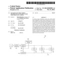
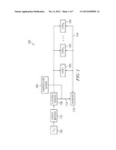
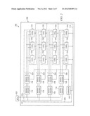
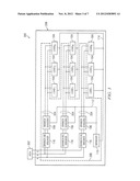
[0002] FIGS. 1-4 are schematic diagrams generically illustrating, by way of example, a variety of electric energy distribution systems according to embodiments of the invention.
[0003] FIG. 5 is a block diagram illustrating a current capping scheme according to the prior art.
[0004] FIG. 6 is a state diagram illustrating example behavior of a load according to embodiments of the invention.
[0005] FIG. 7 is a block diagram illustrating example internal state of a manager component according to embodiments of the invention.
[0006] FIG. 8 is a flow diagram illustrating methods for managing an electric energy distribution system according to embodiments of the invention.
[0007] FIG. 9 is a block diagram illustrating an example configuration of management settings according to embodiments of the invention.
[0008] FIG. 10 is a block diagram illustrating loads in varying example states of an electric energy distribution system according to embodiments of the invention.
DETAILED DESCRIPTION
[0009] FIGS. 1-4 illustrate a variety of classes of implementations of electric energy distribution systems according to embodiments of the invention. The embodiments are shown by way of example and not by way of limitation. Persons having ordinary skill in the art and having reference to the examples given herein will be able to apply the teachings of the examples to other configurations and in other contexts.
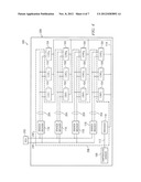
[0010] Refer first to the generic example of FIG. 1. In an electric energy distribution system 100, plural loads 104 are configured to receive electric energy from a common feed 102. Loads 104 may include any type and combination of electrical loads. In some embodiments, the loads may be computing devices such as server computers. A sensor component 106 and/or 108 is configured to monitor a parameter that corresponds to an aggregate amount of electric energy being consumed by loads 104 from feed 102. For example, the parameter may correspond to one or more electrical values as in the case of electric sensor 106, or to a temperature as in the case of temperature sensor 108. A system 100 need not have both types of sensors. A manager component 110 is coupled to sensor component 106 and/or 108 via a sensor bus 112 and is configured to determine whether the parameter meets or exceeds a threshold. If the parameter meets or exceeds the threshold, manager component 110 may change the state of loads 104 by signaling over a management bus 114. A circuit breaker 116 may also be provided on common feed 102.
[0011] Sensor component 106 may be designed to sense current or voltage or both. In the latter case, the sensed values may be utilized to determine a volt-ampere product ("VA") or may be utilized to determine a level of power. Persons having skill in the art will appreciate that VA and power are not always identically the same due to characteristics of some loads that may lead to a non-unity power factor. Any conventional technique may be used to measure the parameter of interest. For example, sense resistors, current transformers or Hall-effect devices may be used.
[0012] Sensor component 108 may be designed to sense a temperature somewhere on or near loads 104. Any conventional temperature sensing device may be employed. In embodiments that use a temperature sensor 108, it is believed that enhanced accuracy will be obtained by sensing a temperature inside an enclosure 208 that houses all of loads 104. (See FIGS. 2-4.) For example, enclosure 208 may be a rack in a data center for embodiments in which loads 104 are computing devices. Moreover, some embodiments may usefully employ more than one temperature sensor 108. For example, multiple temperature sensors 108 may be positioned in or around enclosure 208 or components therein so as to sense inlet and outlet temperatures related to movement of a fluid cooling medium such as air or liquid.
[0013] Manager component 110 may be implemented as a discrete component as shown or its functionality may instead be provided by one of loads 104. Manager 110 may be integrated with or into other components if necessary or convenient to do so.
[0014] In some embodiments, manager component 110 and sensor component 106 and/or 108 may be housed within a PDU 206 (again see FIGS. 2-4) and the PDU mounted in a rack. Manager component 110 and sensor components 106, 108 need not be included within PDU 206 in every embodiment, however.
[0015] Buses 112, 114 may take any conventional form, including for example digital serial or parallel buses or one or more wires carrying analog signals. Any signaling protocol may be used. Buses 112, 114 may be different buses in some embodiments or the same bus in other embodiments.
[0016] As FIGS. 2-4 illustrate, specific embodiments of the invention can take a wide variety of forms. In general, multiple branches 204 may be taken from the common feed. Multiple loads 104 may be disposed on each branch. Any number of branches can be provided, and any number of loads can be provided per branch. A separate circuit breaker 116 may be provided on each branch 204. In these kinds of embodiments, sensors 106 may be employed on a per-branch basis, as shown. In some embodiments, one or more of circuit breakers 116 may be ganged together so that, should one breaker trip, the rest of the ganged breakers will trip as well.
[0017] FIGS. 2 and 3 illustrate that even the type of feed 102 can vary. Feed 202 in system 200 takes the form of a two-line alternating current ("AC") feed. Both lines may be hot or one line may be hot and the other neutral. Feed 302 in system 300 is a three-wire AC feed. In the latter type of embodiments, typically each of wires A, B, C is hot, and they are 120 degrees out of phase with one another. Two-line branches 204 can be taken from any pair of the three wires, as shown. In still other cases, four wires may be present including three hot and one neutral. In those cases, branches may be taken from A to neutral, B to neutral and/or C to neutral. Other combinations and variations are possible.
[0018] FIG. 4 illustrates that, in some embodiments, temperature sensor 108 may be employed in lieu of electric sensors 106. System 400 could just as easily use any of the feed type variations described in relation to the other example embodiments.
[0019] It is known in the prior art for a server computer having its own power supply to be able to self-limit its current draw roughly at or below a constant cap. Specifically, a prior art server computer can be manually configured with a current cap value. In operation, such a server computer will invoke a current-reduction mode when a current value being sensed at its own power supply reaches a threshold value. In the current-reduction mode, typically the central processing unit ("CPU") or other components within the server computer are idled according to a predetermined duty cycle. Thus the server computer can continue to do useful work during portions of the duty cycle in which the CPU is not idled, but over time will draw less current than when not in the current-reduction mode. Although the current cap value for a prior art server computer is manually reconfigurable, the current cap is constant during operation absent manual intervention.
[0020] One problem with the constant cap feature of prior art server computers is illustrated in FIG. 5. Assume that the three servers of FIG. 5 all draw current through a common circuit breaker having a trip level indicated by threshold 500. In order to ensure that the breaker is never tripped, the constant cap level for each server must be chosen so that the sum of the three do not exceed threshold 500, as illustrated at column 502. But in ordinary operation, it may be common for two of the servers (say servers 2 and 3) to require less than their constant cap, and for one of them (say server 1) to desire more than its constant cap will allow. In this event, server 1 is constrained to operate at a maximum current draw dictated by its constant cap, as illustrated at column 504. The result is wasted capacity 506 that could have been employed usefully by server 1. Embodiments according to the invention help to alleviate this problem.
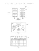
[0021] As FIG. 6 illustrates, a load 104 according to embodiments of the invention may be designed to operate in at least two modes 600, 602, each corresponding to a different cap level. Moreover, load 104 may be designed to adjust its cap level dynamically during operation in response to a command from manager component 110 received over management bus 114, as shown at 604 and 606. In one type of embodiment, management component 110 may communicate a desired cap level to load 104 in each of cases 604, 606. In another type of embodiment, load 104 may associate each of modes 600, 602 with a predetermined cap level internally, and management component 110 may simply select a mode in cases 604, 606. The mechanism for causing load 104 to comply with a given cap level, once the cap level or corresponding mode has been indicated, may be according to any conventional technique including the one described in the immediately preceding paragraph.
[0022] By way of example, mode 600 may correspond to cap level C1, and mode 602 may correspond to cap level C2. Cap level C2 is lower than cap level C1. Thus the maximum current a load 104 may consume when operating at cap=C2 will be less than that of a load operating at cap=C1. Cap level C1 may also correspond to a mode in which no current-reduction technique is employed at all, or equivalently to a mode in which the duty cycle of any current-reduction mechanism employed in the load is set to 100%.
[0023] FIG. 7 illustrates example internal state of management component 110. In general, manager 110 may keep a set of information relating to each of loads 104. Specifically, it may keep values that define C1 and C2 for each load, such as values A and B for load L1 as shown in columns 706, 708. Value A might correspond to a first current level or duty cycle or mode, and value B might correspond to a second current level or duty cycle or mode. The values of C1 may be different for each load or they may be the same. Likewise, the values of C2 may be different for each load or they may be the same. For implementations that include multiple branches as do systems 200, 300, 400, manager 110 may associate each load with a branch identifier as shown in the table at column 702. Manager 110 may keep some value in state column 704 to indicate in which mode or at which cap or duty cycle the given load is currently operating. Finally, manager 110 may establish a priority ordering across all loads. 104 on a given branch by associating a priority value 700 with each load. All of the values in the table of FIG. 7 may be configured by an administrator, for example by means of a graphical user interface provided by manager 110 or by one of loads 104 via a network connection. Any conventional data structures or techniques may be used to store the information just described; it need not be stored in a table format per se.
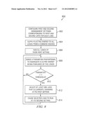
[0024] Example behavior of management component 110 will now be described below in relation to FIGS. 8-10. Referring to method 800 in FIG. 8, in step 802 an administrator configures first and second management settings 706, 708 corresponding to caps C1 and C2 for each load 104.
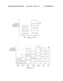
[0025] One example of step 802 is illustrated in FIG. 9. In column 900, the administrator sets caps C2 such that, if all loads 104 were simultaneously to operate at their respective C2 cap levels, the aggregate electric energy consumed by the loads would not exceed a threshold energy level 902. Threshold energy level 902 might correspond to a trip level of a circuit breaker 116 on the branch, or it may correspond to some other threshold such as a temperature, a power level or a VA level. In column 904, the administrator sets caps C1 such that, if loads 104 were simultaneously to operate at their respective C1 cap levels, the aggregate electric energy consumed by the loads would exceed threshold energy level 902. In implementations that include multiple branches 204, the above settings may be made branch-specific by summing the caps only for loads 104 on the relevant branch and comparing the sums with a threshold 902 that may be specific to that branch.
[0026] Referring again to FIG. 8, in step 804 electrical energy is supplied to loads 104 from a common source or feed 102, 202, 302 or branch 204. In step 806, the loads are allowed to run at their respective first management settings C1. In step 808, a parameter corresponding to components 106 and/or 108 is sensed. The value of the parameter is compared, either in the sensor components or in the manager component or elsewhere, with the relevant threshold 902. If it is determined in step 810 that the parameter is below threshold 902, operation resumes at step 808. But if it is determined that the parameter equals or exceeds the threshold, then in step 812 manager 110 selects at least one load 104 that is currently running, at its first management setting C1, and in step 814 causes the selected load 104 to run at its second management setting C2. Operation then resumes at step 808.
[0027] In some embodiments, step 812 may be performed such that manager 110 uses priority information 700 and state information 704 to select the lowest priority load 104 that is currently running at its first management setting C1.
[0028] FIG. 10 illustrates an example of how method 800 may perform in a three-load embodiment under various conditions. In the example, the symbols L1, L2 and L3 represent the actual energy levels being consumed by a given load at the relevant time. The symbols C1, C2 represent the configured cap levels in the table of FIG. 7 for a particular load. Management setting refers to the mode or cap level that is currently in effect for a given load by virtue some communication that has occurred between manager 110 and the given load. Assume that the first load is priority 1, the second load is priority 2 and the third load is priority 3.
[0029] In column 1000, each of the three loads is running at its first management setting C1 (as dictated by step 806) but is actually consuming an energy level less than its configured cap level C2. In column 1002, the first load experiences a need to consume more energy. So it is able to increase its consumption level up to its configured cap level C1. In column 1004, the third load also experiences a need to consume more energy. So it increases its consumption level above what would correspond to its configured cap level C2 and begins to approach its configured cap level C1. But when this happens the sensor component and/or manager component detect a breach of threshold 902. So the manager executes steps 812 and 814, this time selecting the third load because of its low priority, and instructing the third load to run at management setting C2. The consequence is that the third load constrains its energy consumption to its lower configured cap C2, as shown at column 1006. All the while, the first load is still able to consume up to its higher configured cap C1 because of its higher priority.
[0030] In column 1008, assume now that the second load experiences a need to increase its energy consumption, and that it begins consuming energy at a level higher than its configured cap C2. The result in this case is another threshold violation. So manager 110 again executes steps 812 and 814. This time it selects the second load because the second load is now the lowest priority load currently running at its first management setting C1. Manager 110 instructs the second load to run at its second management setting C2, as shown in column 1010. But in this case the result is still a threshold violation. So manager 110 executes steps 812 and 814 one more time. On this final iteration, it selects the first load because it is now the lowest priority load currently operating at its first management setting C1. It instructs the first load to run at its second management setting C2, as shown in column 1012. All three loads may now operate safely below threshold 902. But the highest priority load was allowed to operate at its highest energy consumption longer than the other two, lower-priority loads.
[0031] While the invention has been described in detail with reference to preferred embodiments thereof, the described embodiments have been presented by way of example and not by way of limitation. It will be understood by those skilled in the art and having reference to this specification that various changes may be made in the form and details of the described embodiments without deviating from the spirit and scope of the invention as defined by the appended claims.
User Contributions:
Comment about this patent or add new information about this topic:
Images included with this patent application:
 |  |
 |  |
 |  |
 |  |
| Similar patent applications: | |
| Date | Title |
|---|---|
| 2012-10-18 | Method for bank note distribution of financial self-service equipment |
| 2011-06-02 | Self-service kiosk with multiple secure service areas |
| 2011-12-22 | Machining error corrector method using optical pickup |
| 2012-08-09 | Managing an infrastructure housing disaggregated heat sources |
| 2013-01-31 | Electric vehicle charging station remote disconnect system |
| New patent applications in this class: | |
| Date | Title |
|---|---|
| 2018-01-25 | Audit method and system and supply method and system for pv power injection and consumption in a power grid system |
| 2016-09-01 | Systems and methods for remotely powering, configuring and controlling dc powered multi-channel devices |
| 2016-07-07 | Power demand and supply control apparatus and method thereof |
| 2016-06-30 | Unit and method for energy regulation of an electrical production and consumption system |
| 2016-06-30 | Latency-based micro demand response |
| New patent applications from these inventors: | |
| Date | Title |
|---|---|
| 2022-01-06 | Power management system for maintaining bus voltage |
| 2022-01-06 | System controller for monitoring a characteristic system energy of a computing system |
| 2021-02-04 | Two-stage step-down converter |
| 2019-01-03 | Variable soft start |
| 2018-12-27 | Serial bootloading of power supplies |
| Top Inventors for class "Data processing: generic control systems or specific applications" | |
| Rank | Inventor's name |
|---|---|
| 1 | Kyung Shik Roh |
| 2 | Lowell L. Wood, Jr. |
| 3 | Mark J. Nixon |
| 4 | Royce A. Levien |
| 5 | Yulun Wang |