Patent application title: PATCH AND DEVICE FOR CLEANING FIREARMS
Inventors:
Paolo Marco Maria Taveggia (Arese Mi, IT)
IPC8 Class: AF41A2900FI
USPC Class:
42 90
Class name: Firearms implements
Publication date: 2012-11-01
Patent application number: 20120272559
Abstract:
The invention relates to a patch (1) for cleaning firearms, comprising a
circular central portion (1a) and a plurality of flaps (1b) extending
therefrom radially outwards. Thanks to the presence of the flaps (1b) it
is possible to achieve a uniform contact between the patch (1) and the
surface of a cavity (C) to be cleaned, thus minimizing the formation of
pleats in the patch (1) and allowing to reduce the number of sweeps and
rotations of the patch (1) and of the cleaning device during cleaning.
The invention also relates to a device for cleaning firearms comprising
at least one patch (1) and at least one supporting member (2) suitable to
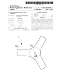
allow to fix the at least one patch (1).Claims:
1. A patch for cleaning firearms, comprising a circular central portion
and a plurality of flaps extending therefrom radially outwards.
2. A patch according to claim 1, wherein said circular central portion comprises a guiding hole suitable to allow to fit the patch onto a supporting member.
3. A device for cleaning firearms, comprising at least one patch according to claim 1 and at least one supporting member suitable to allow to fix the at least one patch, said supporting member being formed of a cylindrical body that is provided at its distal end with a tip suitable to pierce the patch.
4. A cleaning device according to claim 1, wherein said tip comprises one or more grooves formed in the circumferential direction and suitable to block the movement of the patch along the axial direction.
5. A cleaning device according to claim 3, further comprising at least one extending member and in that the supporting member further comprises connection means arranged at its proximal end and suitable to allow the connection of the supporting member with the extending member.
6. A cleaning device according to claim 3, wherein the diameter of the cylindrical body is substantially equal to the diameter of the circular central portion of the patch.
7. A cleaning device according to claim 3, wherein the supporting member is sized so as to define with respect to a cavity (C) to be cleaned a play corresponding to the thickness of the patch.
8. A cleaning device according to claim 3, further comprising a plurality of interchangeable supporting members having a different diameter.
9. A cleaning device according to claim 3, further comprising a plurality of patches equal to each other, said patches being superimposed on the supporting member and so rotated relative to each other that their respective flaps do not overlap.
Description:
[0001] The present invention relates to a patch and a device for cleaning
firearms, and in particular for cleaning deep cavities such as those of a
barrel and a drums.
[0002] In the field of firearms, e.g. for use in sports, there is a strong need to clean a firearm after each use. In addition to cleaning the mechanisms related to the trigger and to the load of the ammunitions, a good cleaning of the cavities of e.g. barrel and drum, through which ammunitions pass is very important. In fact the cavities of barrel and drum are those where dust and dirt are more easily built up. Moreover, residuals of gunpowder mixed with lubricants that are normally used to maintain a firearm fully efficient are built up over time in cavities of barrel and drum. It is well known that a lack of maintenance or a poor maintenance of a firearm causes wear-out and malfunctioning during use.
[0003] Generally, the cleaning of the cavities of a firearm is carried out mechanically by brushing and/or with the aid of suitable chemical solvents. After the step of mechanical and/or chemical cleaning it is necessary to carry out a lubrication step, which is generally carried out by using patches soaked with special lubricants.
[0004] Numerous devices for cleaning firearms are known, generally comprising rigid or flexible rods at whose distal end brushes are arranged, or patches made of a textile material, e.g. cotton or synthetic fibers, are fixed. There are also devices configured to receive both brushes and patches in different combinations.
[0005] Patent EP 0082230 discloses, for example, a device for cleaning firearms comprising a rod at one end of which a brush having a cylindrical shape is coaxially arranged. The device also comprises a patch made of a textile material and having the shape of a sleeve suitable to be fitted and fixed onto the cylindrical brush.
[0006] U.S. Pat. No. 4,399,627 discloses a device for cleaning the barrel of a firearm comprising a flexible rod at one end of which a threaded connection is rotatably arranged, which is suitable to allow to mount a cylindrical brush having a size corresponding to the bore of the firearm. At the opposite end of the rod a slotted member is rotatably arranged, which is suitable to allow the insertion of a patch for further cleaning and lubricating the barrel.
[0007] Other cleaning devices for firearms are disclosed, for example, in patent publications US 2006/147247, US 2006/236584, US 2007/266610 and in patent U.S. Pat. No. 4,962,607.
[0008] The patches used with the cleaning devices for firearms are preferred to the brushes because the are very cheap and disposable products that allow to carry out cleaning operations as well as the lubrication of the cavities of a firearm. Moreover, differently from most of the brushes, patches are substantially independent of the bore of the firearm, which allows to use them in an extremely flexible way with firearms having different bores.
[0009] A problem of the known patches for cleaning firearms is that, once inserted into the cavity of a barrel or a drum, they do not fold uniformly without the assistance from a user and thus they may not completely contact the inner surface of the cavity to be cleaned and/or lubricated. Therefore, the user must make multiple sweeps and rotations of the patch throughout the cavity to completely clean and/or lubricate it. This is remarkably time consuming and may lead a user to neglect the maintenance of the firearm with the above-described negative consequences.
[0010] A possible solution to this problem is proposed by the international publication WO 2010/019267, which discloses a planar triangular patch for cleaning firearm bores. The patch has similarly sized notches placed centrally along the edges of the patch, permitting a uniform level of pleating as the patch is inserted into a firearm bore and wraps around a jag.
[0011] However, the presence of a number of pleats in a folded patch still results in portions of the patch that do not contact the inner surface of the cavity, thus requiring the user to make multiple sweeps and rotations of the patch throughout the cavity to be cleaned or lubricated.
[0012] It is therefore an object of the present invention to provide a patch and a device for cleaning firearms, which allow to overcome said disadvantages. Said object is achieved with a patch and a cleaning device, whose main features are disclosed in claims 1 and 3, respectively, while other features are disclosed in the remaining claims.
[0013] An idea of solution to the technical problem of minimizing the number of sweeps and rotations of a cleaning device employing patches is that of providing the patch with a plurality of flaps protruding radially outwards from a central portion having a circular shape. When the patch is inserted into the cavity to be cleaned the flaps are folded by 90° with respect to the circular central portion thus progressively going into contact with the surface of the cavity and coming closer and closer to each other up to forming a cylindrical surface that is substantially homogeneous and compact. In such a way a uniform contact between the patch and the surface of the cavity to be cleaned is obtained, thus preventing or minimizing the formation of pleats and allowing to reduce the number of sweeps and rotations of the patch and the cleaning device during the cleaning and lubricating operations.
[0014] The main advantage offered by the invention is to allow an effective cleaning of the cavities of a firearm in times that are remarkably shorter than those required when patches of a known type are used.
[0015] The device of the invention comprises at least one patch and a supporting member suitable to allow to fix and maneuver the patch. The supporting member has a rather small size in an axial direction in order to allow an easy cleaning of cavities that are not too deep, e.g. the cavities of a gun drum, but may advantageously be connected to an extending member, such as e.g. a rigid or flexible rod, in order to allow to clean deeper cavities such as e.g. the cavity of a rifle barrel.
[0016] The supporting member is so sized to define with respect to the surface of the cavity to be cleaned a play that substantially corresponds to the thickness of the patch, thus allowing to achieve not only a complete contact between the flaps of the patch and the surface of the cavity, but also a rubbing action allowing to remove dust and residuals of gunpowder.
[0017] The idea of providing the patch with foldable flaps advantageously allows to adapt a single patch to cavities having different diameters by simply using supporting members suitable to define with the cavity to be cleaned a play each time corresponding to the thickness of the patch. Consequently, it is possible to standardize the shape and size of the patches, thus reducing their manufacturing costs.
[0018] Further advantages and features of the patch and the cleaning device according to the present invention will become clear to those skilled in the art from the following detailed and non-limiting description of embodiments thereof with reference to the attached drawings, wherein:
[0019] FIG. 1 shows a patch according to the invention;
[0020] FIGS. 2 and 3 respectively show a top view and a partial longitudinal section of a first embodiment of a cleaning device according to the invention;
[0021] FIG. 4 shows the cleaning device of FIGS. 2 and 3 inserted in a cavity of a firearm; and
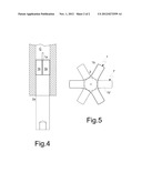
[0022] FIG. 5 shows a top view of a second embodiment of a cleaning device according to the invention.
[0023] Referring to FIG. 1, a patch 1 according to the invention comprises a central portion 1a having a circular shape and a plurality of flaps 1b extending therefrom radially outwards. The patch 1 may be made of a textile material such as cotton, synthetic fibers or other textile materials that are generally used in the manufacturing of patches for cleaning cavities of firearms.
[0024] The patch 1 is generally used together with cleaning devices comprising a supporting member on which the patch is inserted before the introduction of the cleaning device into the cavity to be cleaned. In order to ease the insertion of the patch 1 onto the supporting member, the circular central portion 1a of the patch 1 may advantageously comprise a guiding hole 1c.
[0025] Referring to FIGS. 2 and 3, the cleaning device according to the invention comprises a supporting member 2 formed of a body 2a having a substantially cylindrical shape. The cylindrical body 2a is provided at a distal end thereof with a tip 2b adapted to pierce the patch 1, e.g. through the guiding hole 1c, in order to allow to arrange and fix it. Once inserted on the tip 2b, the patch 1 abuts a top surface 2c of the cylindrical body 2a, which thus blocks the movement of the patch 1 along the axial direction.
[0026] The supporting member 2 has a rather small size in the axial direction, e.g. comprised between 4 and 8 cm, in order to ease the cleaning of cavities having a small depth such as e.g. those of the drum of a gun. In order to allow to clean deeper cavities such as e.g. the cavity of a rifle barrel, the cleaning device of the invention may further comprise at least one extending member (non shown), e.g. a rigid or flexible rod. Correspondingly, the supporting member 2 is provided with connection means 4 arranged at a proximal end 2d opposite to the distal end adapted to receive the patch 1, i.e. where the tip 2b is arranged.
[0027] As shown in FIG. 3, the connection means 4 may be made in the form of a threaded connection. Alternatively, the connection means 4 might be made in the form of a snap or magnetic connection, as well as in many other equivalent ways well known to a skilled person.
[0028] The supporting member 2 is so sized to define with respect to the cavity to be cleaned a play that substantially corresponds to the thickness of the patch 1.
[0029] As shown in FIG. 4, once inserted the device into the cavity C to be cleaned, the flaps 1b are folded and contact on one side the surface of the cavity C and on the other side the cylindrical body 2a of the supporting member 2. In this way it is possible to achieve an effective rubbing action of the patch 1 against the surface of the cavity C to be cleaned, which facilitates both the removal of dirt and the subsequent lubrication step and allows to minimize the number of sweeps and rotations of the patch and the cleaning device.
[0030] The supporting member 2 has a diameter substantially equal to the diameter of the circular central portion 1a of the patch 1, whereby the flaps 1b are folded proximate to the periphery of the circular central portion 1a. Moreover, the flaps 1b are suitably spaced from one another in a circumferential direction so as to come close to one another without overlapping and forming pleats once in contact with the surface of the cavity C to be cleaned. In the embodiment shown in FIGS. 1 to 4, the patch is provided in particular with three flaps arranged at 120° from one another in the circumferential direction.
[0031] The number of flaps 1b and their distance along the circumferential direction are so configured to obtain a cylindrical surface that is substantially homogeneous when the fold line of the flaps 1b is in correspondence to the periphery of the circular central portion 1a. Consequently, in order to correctly clean all the possible cavity sizes a patch 1 and a supporting member 2 having a size corresponding to the size of the specific cavity C would be needed, which would be poorly convenient, expensive and contrary to the aim of the invention.
[0032] According to a further aspect of the invention, it is possible to use a single patch 1 for cleaning cavities C of firearms having different bores. To this end, the device comprises a plurality of supporting members 2 that can be chosen and interchanged on the basis of the diameter of the cavity C to be cleaned. In this way, it is always possible to maintain between the cavity C and the supporting member 2 a play that is equal to the thickness of the patch 1, thus allowing to achieve an effective rubbing action of the patch 1 against the surface of the cavity C and avoiding problems of misalignment between the latter and the supporting member 2, which make the cleaning sweeps more difficult and might result in peaking of the cleaning device in the cavity C during cleaning.
[0033] It is clear that by using a supporting member 2 having a diameter larger than the diameter of the circular central portion 1a of the patch 1, the flaps 1b will not be folded at the periphery of the circular central portion 1a, but at an outer zone, thus resulting in a number of discontinuities, i.e. longitudinal apertures, in the cylindrical surface covering the supporting member 2 once inserted in the cavity C. This drawback may easily be solved by using at the same time a number of patches 1, 1', . . . identical to each other and by arranging them superimposed to each other and so rotated relative to each other that their respective flaps (1b, 1b', . . . ) are spaced along the circumferential direction without overlapping. In this way, once inserted the cleaning device into the cavity C, the flaps 1b, 1b', . . . will be adjacent to each other thus forming a cylindrical surface that is substantially homogeneous.
[0034] For example, FIG. 5 shows a second embodiment of the device according to the invention comprising two patches 1, 1' each having three flaps 1b, 1b' spaced by 120° from each other along the circumferential direction. The patches 1, 1' are mutually rotated by about 60°, whereby the flaps 1b' are aligned with the bisecting line of the 120° angle between the flaps 1b, thus allowing to achieve a very homogeneous cleaning surface on the cylindrical body 2a of the supporting member 2.
[0035] The embodiments of the invention herein disclosed and illustrated are only examples susceptible of numerous variants. For example, the supporting member 2 might comprise one or more grooves formed in the tip 2b in a circumferential direction, thus allowing not only to block the movement of the patch 1 along the axial direction, but also to hold it during sweeping, thereby allowing to make cleaning sweeps not only from the entry of the cavity to the exit, but also in the opposite direction. Further, with particular reference to the possibility of using patches of a standard size in combination with interchangeable supporting members of a different diameter, it is also possible to foresee the use of a number of standard patches of different size, each one adapted to fit cavities having diameters comprised in predefined ranges.
User Contributions:
Comment about this patent or add new information about this topic:
Images included with this patent application:
 |  |
 |
| Similar patent applications: | |
| Date | Title |
|---|---|
| 2011-07-21 | Holding device for rail equipped firearms |
| 2011-09-08 | Bipod device for use with a firearm |
| 2011-10-06 | Device for cleaning gun barrels |
| 2012-08-09 | Magazine release device for firearms |
| 2012-11-29 | System and method of controlling discharge of a firearm |
| New patent applications in this class: | |
| Date | Title |
|---|---|
| 2022-05-05 | Configurable cable holder for firearms |
| 2019-05-16 | Universal gun rail mount for accessories |
| 2018-01-25 | Movable firearm accessory support assembly |
| 2016-12-29 | Rear sight block for ak-type rifles |
| 2016-09-01 | Mounting assembly |
| New patent applications from these inventors: | |
| Date | Title |
|---|---|
| 2014-02-20 | Packaging and packaging method for patches made of a textile material |
| Top Inventors for class "Firearms" | |
| Rank | Inventor's name |
|---|---|
| 1 | Michael T. Mayberry |
| 2 | Mark C. Laney |
| 3 | Stephen P. Troy |
| 4 | Russell A. Potterfield |
| 5 | Dennis Cauley |