Patent application title: METHOD FOR MAKING COATED ARTICLE AND COATED ARTICLE
Inventors:
Hsin-Pei Chang (Tu-Cheng, TW)
Hsin-Pei Chang (Tu-Cheng, TW)
Wen-Rong Chen (Tu-Cheng, TW)
Wen-Rong Chen (Tu-Cheng, TW)
Huann-Wu Chiang (Tu-Cheng, TW)
Huann-Wu Chiang (Tu-Cheng, TW)
Cheng-Shi Chen (Tu-Cheng, TW)
Jia Huang (Shenzhen City, CN)
Assignees:
HON HAI PRECISION INDUSTRY CO., LTD.
HONG FU JIN PRECISION INDUSTRY (ShenZhen) CO., LTD.
IPC8 Class: AB32B1706FI
USPC Class:
428336
Class name: Coating layer not in excess of 5 mils thick or equivalent up to 3 mils 1 mil or less
Publication date: 2012-10-11
Patent application number: 20120258304
Abstract:
A method for making a coated article includes: providing a substrate;
forming a prefabricated layer on a surface of the substrate by vacuum
sputtering, the prefabricated layer being a metal layer containing the
metal element `N`, or an unsaturated oxide layer containing the metal
element `N` and `M`, the `N` being one or more metals selected from a
group consisting of titanium, aluminum, and zinc, the `M` being calcium,
barium, or a mixture of calcium and barium; and thermal oxidizing the
prefabricated layer to form a color layer on the substrate, the color
layer being an oxide layer of the metal element `N`, or an oxide layer of
the metal element `N` and `M`. The color value of the color layer has a
L* coordinate between 91 and 98, an a* coordinate between -1 and 1, and a
b* coordinate between -2 and 2 in the CIE LAB color system.Claims:
1. A method for making a coated article, comprising: providing a
substrate; forming a prefabricated layer on a surface of the substrate by
vacuum sputtering, the prefabricated layer being a metal layer containing
the metal element `N`, or an unsaturated oxide layer containing the metal
element `N` and the metal element `M`, the metal element `N` being one or
more metals selected from a group consisting of titanium, aluminum, and
zinc, the metal element `M` being calcium, barium, or a mixture of
calcium and barium; and thermal oxidizing the prefabricated layer to form
a color layer on the substrate, the color layer being an oxide layer of
the metal element `N`, or an oxide layer of the metal element `N` and the
metal element `M`; the color value of the color layer having a L*
coordinate between 91 and 98, an a* coordinate between -1 and 1, and a b*
coordinate between -2 and 2 in the CIE LAB color system.
2. The method as claimed in claim 1, wherein forming the prefabricated layer uses argon as a working gas, the argon having a flow rate of about 300 sccm-500 sccm; uses a metal target, the metal target being made of one or more metals selected from a group consisting of titanium, aluminum, and zinc, the metal target being applied with a power of about 2.5 kW-4.5 kW; conducting the sputtering of the prefabricated layer at a temperature of about 100.degree. C.-300.degree. C. and for about 1 hour-4 hours.
3. The method as claimed in claim 2, wherein the substrate has a bias voltage of about -200 V to about 0 V during sputtering of the prefabricated layer.
4. The method as claimed in claim 1, wherein forming the prefabricated layer uses argon as a working gas, the argon having a flow rate of about 300 sccm-500 sccm; uses a metal target and a ceramic target, the metal target being made of one or more metals selected from a group consisting of titanium, aluminum, and zinc, the ceramic target being made of calcium oxide, barium oxide, or a mixture of calcium oxide and barium oxide, the metal target being applied with a power of about 2.5 kW-4.5 kW, the ceramic target being applied with a power of about 3 kW-4.5 kW; conducting the sputtering of the prefabricated layer at a temperature of about 100.degree. C.-300.degree. C. and for about 1 hour-4 hours.
5. The method as claimed in claim 4, wherein the substrate has a bias voltage of about -200 V to about 0 V during sputtering of the prefabricated layer.
6. The method as claimed in claim 1, wherein thermal oxidizing the prefabricated layer is carried out at about 300.degree. C.-600.degree. C. using oxygen as a reaction gas having a flow rate of about 80 sccm-150 sccm for about 20 min-60 min.
7. The method as claimed in claim 1, wherein the color layer has a thickness of about 1 μm-2 μm.
8. The method as claimed in claim 1, wherein color value tested on the substrate has a L* coordinate between 85 and 90, an a* coordinate between -2 and 1, and a b* coordinate between -2 and 2 in the CIE LAB color system.
9. The method as claimed in claim 1, further comprising a step of pre-treating the substrate before forming the prefabricated layer.
10. The method as claimed in claim 1, wherein the substrate is transparent and made of glass.
11. A coated article, comprising: a substrate; and a color layer formed on a surface of the substrate, the color layer being an oxide layer of the metal element `N`, or an oxide layer of the metal element `N` and the metal element `M`; the color value of the color layer having a L* coordinate between 91 and 98, an a* coordinate between -1 and 1, and a b* coordinate between -2 and 2 in the CIE LAB color system.
12. The coated article as claimed in claim 11, the color layer having a thickness of about 1 μm-2 μm.
13. The coated article as claimed in claim 11, the color layer being white.
14. The coated article as claimed in claim 11, wherein color value tested on the substrate has a L* coordinate between 85 and 90, an a* coordinate between -2 and 1, and a b* coordinate between -2 and 2 in the CIE LAB color system.
15. The coated article as claimed in claim 1, the substrate being transparent and made of glass.
Description:
BACKGROUND
[0001] 1. Technical Field
[0002] The present disclosure relates to methods for making coated articles, especially to a method for making a coated article having a white color and a coated article made by the method.
[0003] 2. Description of Related Art
[0004] To decorate housings of electronic devices, decorative layers may be formed on the housings by anodizing, painting, or vacuum depositing. However, the anodizing and painting processes are not environmentally friendly, and decorative layers formed by vacuum depositing may not have rich colors.
[0005] Therefore, there is room for improvement within the art.
BRIEF DESCRIPTION OF THE FIGURES
[0006] Many aspects of the disclosure can be better understood with reference to the following figures. The components in the figures are not necessarily drawn to scale, the emphasis instead being placed upon clearly illustrating the principles of the disclosure. Moreover, in the drawings like reference numerals designate corresponding parts throughout the several views.
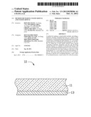
[0007] FIG. 1 is a cross-sectional view of an exemplary embodiment of a substrate and a prefabricated layer.
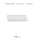
[0008] FIG. 2 is a cross-sectional view of an exemplary embodiment of a coated article.
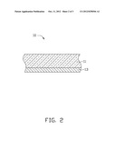
[0009] FIG. 3 is a schematic view of an exemplary embodiment of a vacuum sputtering device.
DETAILED DESCRIPTION
[0010] Referring to FIG. 1 and FIG. 2, according to an exemplary embodiment, a method for making a coated article 10 may include the following steps:
[0011] A substrate 11 is provided. The substrate 11 may be transparent and made of glass, for example.
[0012] The substrate 11 is pre-treated. The pre-treating process may include cleaning contaminants from the substrate 11, and rinsing the substrate 11 in deionized water and then drying.
[0013] A prefabricated layer 12 is sputtered on the pretreated substrate 11. The prefabricated layer 12 may be a metal layer containing the metal element `N`, or an unsaturated oxide layer containing the metal element `N` and the metal element `M`. The metal element `N` may be one or more metals selected from a group consisting of titanium (Ti), aluminum (Al), and zinc (Zn). The metal element `M` may be calcium (Ca), barium (Ba), or a mixture of Ca and Ba.
[0014] Referring to FIG. 3, the substrate 11 may be positioned in a coating chamber 21 of a vacuum sputtering device 20. The coating chamber 21 is fixed with a metal target 23 and a ceramic target 24. The metal target 23 may be made of one or more metals selected from a group consisting of Ti, Al, and Zn. The ceramic target 24 is made of calcium oxide (CaO), barium oxide (BaO), or a mixture of CaO and BaO.
[0015] The coating chamber 21 is then evacuated to about 8.0×10⁻³ Pa. Argon (Ar) gas having a purity of about 99.999% may be used as a working gas and is fed into the coating chamber 21 at a flow rate of about 300 standard-state cubic centimeters per minute (sccm) to about 500 sccm. The inside of the coating chamber 21 may be heated to about 100° C.-300° C. When the prefabricated layer 12 is a metal layer, a power of about 2.5 kilowatt (kW)-4.5 kW is applied on the metal target 23 to deposit the prefabricated layer 12. When the prefabricated layer 12 is an unsaturated oxide layer, a power of about 2.5 kW-4.5 kW and a power of about 3 kW-4.5 kW at a radio frequency are respectively applied on the metal target 23 and the ceramic target 24 to deposit the prefabricated layer 12. During the depositing process, the substrate 11 may have a bias voltage of about -200 V to about 0 V. Depositing of the prefabricated layer 12 may take about 1 hour-4 hours.
[0016] After the prefabricated layer 12 is formed, the feeding of the argon gas into the coating chamber 21 is stopped, the power applied on the metal target 23 and the power applied on the ceramic target 24 are stopped, and the bias voltage to the substrate 11 is also stopped. The inside of the coating chamber 21 is then heated to about 300° C.-600° C., and oxygen (O2) at a flow rate of about 80 sccm-150 sccm is fed into the coating chamber 21 to thermally oxidize the prefabricated layer 12 and form a color layer 13 having a white color on the substrate 11. The color layer 13 is an oxide layer of the metal element `N`, or an oxide layer of the metal element `N` and `M`. The color layer 13 has a thickness of about 1 μm-2 μm.
[0017] The process of thermal oxidizing the prefabricate layer 12 can also be carried out in an oven.
[0018] The color value of the color layer 13 of the exemplary embodiment has been tested. The test indicated that the color value of the color layer 13 had, in the CIE (international commission on illumination) LAB color system, a L* coordinate between 91 and 98, an a* coordinate between -1 and 1, and a b* coordinate between -2 and 2. When the test is tested on the substrate 11, the L* coordinate is between 85 and 90, the a* coordinate is between -2 and 1, and the b* coordinate is between -2 and 2. Thus, the coated article 10 presents a bright white appearance whether being observed through the substrate 11 or from the color layer 13.
[0019] The substrate 11 can also be opaque and made of metal.
[0020] A coated article 10 formed by the exemplary method includes the substrate 11, and the color layer 13 formed on a surface of the substrate 11.
[0021] Specific examples of making the coated article are described as follows. The pre-treating process in these specific examples may be substantially the same as described above, so it is not described here again. Additionally, the processes of sputtering the prefabricate layer 12 and forming the color layer 13 in the specific examples are substantially the same as described above, and the specific examples merely emphasize the different parameters in the different processes of making the coated article 10.
Example 1
[0022] The substrate 11 is made of glass.
[0023] Sputtering to form the prefabricated layer 12 on the substrate 11: the flow rate of Ar is 400 sccm, the substrate 11 has a bias voltage of -80 V; uses the metal target 23, the metal target 23 is made of zinc and applied with a power of 4 kW; sputtering of the prefabricate layer 12 takes 120 min.
[0024] Thermal oxidizing the prefabricate layer 12 to form the color layer 13: the inside of the coating chamber 21 is heated to 500° C.; the flow rate of the oxygen is 120 sccm; thermal oxidizing the prefabricated layer 12 takes 45 min.
[0025] The color layer 13 has a thickness of 1.68 pm. The color value of the color layer 13 has, in the CIE LAB color system, a L* coordinate of 95, an a* coordinate of 0.52, and a b* coordinate of -0.35. When the test is tested on the substrate 11, the L* coordinate is 87, the a* coordinate is -1.07, and the b* coordinate is -0.85.
Example 2
[0026] The substrate 11 is made of glass.
[0027] Sputtering to form the prefabricated layer 12 on the substrate 11: the flow rate of Ar is 400 sccm, the substrate 11 has a bias voltage of -100 V; uses the metal target 23 and the ceramic target 24, the metal target 23 is made of zinc and applied with a power of 4 kW, the ceramic target 24 is made of calcium oxide and applied with a power of 4 kW; sputtering of the prefabricate layer 12 takes 120 min.
[0028] Thermal oxidizing the prefabricate layer 12 to form the color layer 13: the inside of the coating chamber 21 is heated to 500° C.; the flow rate of the oxygen is 100 sccm; thermal oxidizing the prefabricated layer 12 takes 50 min.
[0029] The color layer 13 has a thickness of 1.8 μm. The color value of the color layer 13 has, in the CIE LAB color system, a L* coordinate of 97, an a* coordinate of 0.27, and a b* coordinate of -0.15. When the test is tested on the substrate 11, the L* coordinate is 88.5, the a* coordinate is -0.97, and the b* coordinate is -0.45.
Example 3
[0030] The substrate 11 is made of glass.
[0031] Sputtering to form the prefabricated layer 12 on the substrate 11: the flow rate of Ar is 400 sccm, the substrate 11 has a bias voltage of -100 V; uses the metal target 23, the metal target 23 is made of titanium and applied with a power of 3.5 kW; sputtering of the prefabricate layer 12 takes 100 min.
[0032] Thermal oxidizing the prefabricate layer 12 to form the color layer 13: the inside of the coating chamber 21 is heated to 550° C.; the flow rate of the oxygen is 120 sccm; thermal oxidizing the prefabricated layer 12 takes 50 min.
[0033] The color layer 13 has a thickness of 1.12 μm. The color value of the color layer 13 has, in the CIE LAB color system, a L* coordinate of 96.5, an a* coordinate of -0.67, and a b* coordinate of 0.11. When the test is tested on the substrate 11, the L* coordinate is 87.2, the a* coordinate is -1.17, and the b* coordinate is 0.53.
Example 4
[0034] The substrate 11 is made of glass.
[0035] Sputtering to form the prefabricated layer 12 on the substrate 11: the flow rate of Ar is 350 sccm, the substrate 11 has a bias voltage of -100 V; uses the metal target 23, the metal target 23 is made of aluminum and applied with a power of 3.5 kW; sputtering of the prefabricate layer 12 takes 100 min
[0036] Thermal oxidizing the prefabricate layer 12 to form the color layer 13: the inside of the coating chamber 21 is heated to 400° C.; the flow rate of the oxygen is 100 sccm; thermal oxidizing the prefabricated layer 12 takes 45 min.
[0037] The color layer 13 has a thickness of 1.35 μm. The color value of the color layer 13 has, in the CIE LAB color system, a L* coordinate of 95.7, an a* coordinate of 0.01, and a b* coordinate of -0.75. When the test is tested on the substrate 11, the L* coordinate is 86.5, the a* coordinate is 0.42, and the b* coordinate is -1.65.
Example 5
[0038] The substrate 11 is made of glass.
[0039] Sputtering to form the prefabricated layer 12 on the substrate 11: the flow rate of Ar is 400 sccm, the substrate 11 has a bias voltage of -100 V; uses the metal target 23 and the ceramic target 24, the metal target 23 is made of zinc and applied with a power of 4 kW, the ceramic target 24 is made of barium oxide and applied with a power of 3.5 kW,; sputtering of the prefabricate layer 12 takes 120 min.
[0040] Thermal oxidizing the prefabricate layer 12 to form the color layer 13: the inside of the coating chamber 21 is heated to 580° C.; the flow rate of the oxygen is 120 sccm; thermal oxidizing the prefabricated layer 12 takes 45 min.
[0041] The color layer 13 has a thickness of 1.91 μm. The color value of the color layer 13 has, in the CIE LAB color system, a L* coordinate of 98, an a* coordinate of 0.01, and a b* coordinate of 0.08. When the test is tested on the substrate 11, the L* coordinate is 89.2, the a* coordinate is 0.29, and the b* coordinate is -0.35.
[0042] It is believed that the exemplary embodiment and its advantages will be understood from the foregoing description, and it will be apparent that various changes may be made thereto without departing from the spirit and scope of the disclosure or sacrificing all of its advantages, the examples hereinbefore described merely being preferred or exemplary embodiment of the disclosure.
User Contributions:
Comment about this patent or add new information about this topic:
| People who visited this patent also read: | |
| Patent application number | Title |
|---|---|
| 20130271529 | HEAD CHIP, LIQUID JET HEAD, AND LIQUID JET RECORDING APPARATUS |
| 20130271528 | INKJET HEAD UNIT AND INKJET RECORDING DEVICE |
| 20130271527 | IMAGE FORMING APPARATUS |
| 20130271526 | BICOMPONENT REACTIVE INK FOR INK JET PRINTING |
| 20130271525 | INKS FOR INKJET PRINTERS |
Images included with this patent application:
 |  |
 |  |
| Similar patent applications: | |
| Date | Title |
|---|---|
| 2011-12-08 | Coating method and coated article |
| 2012-02-02 | Method and apparatus for ripping plate material, and plate material |
| 2012-02-02 | Polyamide composite structures and processes for their preparation field of the invention |
| 2009-08-13 | Laminated paper article and paper web |
| 2012-01-19 | Molding material and resin-adhered reinforcing fiber bundle |
| New patent applications in this class: | |
| Date | Title |
|---|---|
| 2022-05-05 | Gas barrier laminate |
| 2018-01-25 | Process for coating an article and coating produced thereby |
| 2018-01-25 | Coated article supporting high-entropy nitride and/or oxide thin film inclusive coating, and/or method of making the same |
| 2018-01-25 | Decorative sheets and decorative members including the decorative sheets |
| 2017-08-17 | Composition comprising silver nanowires and dispersed polymer beads for the preparation of electroconductive transparent layers |
| New patent applications from these inventors: | |
| Date | Title |
|---|---|
| 2013-07-04 | Anti-counterfeiting article and method thereof |
| 2013-07-04 | Tag holder and workpiece using the same |
| 2013-06-20 | Composite and method for making the same |
| 2013-05-30 | Anti-theft system using rfid tags |
| Top Inventors for class "Stock material or miscellaneous articles" | |
| Rank | Inventor's name |
|---|---|
| 1 | Cheng-Shi Chen |
| 2 | Hsin-Pei Chang |
| 3 | Wen-Rong Chen |
| 4 | Huann-Wu Chiang |
| 5 | Shou-Shan Fan |