Patent application title: Tooth and Adaptor Assembly
Inventors:
Neil Douglas Bentley (Edmonton, CA)
Assignees:
AMSCO CAST PRODUCTS (CANADA) INC.
IPC8 Class: AE02F928FI
USPC Class:
37456
Class name: Tooth or adaptor mounting or retaining means including pin or key
Publication date: 2012-10-04
Patent application number: 20120246982
Abstract:
A tooth and adaptor assembly is provided for a dipper bucket. The
assembly can have an adaptor having a rear portion for attaching to the
dipper bucket, a tooth capable of releasable attachment to the adaptor
and a retainer pin for securing the tooth to the adaptor. The adaptor
comprises a tapering intermediate portion that narrows to a rectangular
front portion, and a wedge portion that extends perpendicularly
therefrom. The adaptor further comprises at least one socket cavity for
receiving a leg extension having an inwardly pointing hook disposed on
the tooth. The tooth has a tip at its front end for digging and a socket
at its rear end configured to receive the front and intermediate portions
of the adaptor. A passageway is formed between the wedge portion and the
leg hook for receiving a retainer pin to secure the tooth to the adaptor.Claims:
1. An adaptor for releasably attaching a tooth to an excavation tool,
said adaptor comprising: a) a rear portion configured for attaching to an
excavation tool; b) a front portion configured for a sliding fit with a
corresponding socket disposed on a tooth; c) an intermediate portion
comprising an exterior surface and a base adjacent to the rear portion,
the intermediate portion narrowing in cross-sectional area from the base
to the front portion; d) a wedge portion extending from a sidewall
disposed on the intermediate portion; and e) a socket cavity disposed in
the sidewall near the wedge portion wherein a passageway is formed when a
leg extension extending from the tooth is inserted into the socket cavity
when the tooth is seated on the adaptor, the passageway configured to
receive a retainer pin for releasably attaching the tooth to the adaptor.
2. The adaptor as set forth in claim 1 wherein the excavation tool is a dipper bucket or a front-end loader bucket.
3. The adaptor as set forth in claim 1 wherein the rear portion is U-shaped and configured to attach to a lip of the excavation tool.
4. The adaptor as set forth in claim 1 wherein the front portion comprises a key further comprising a substantially flat front end.
5. The adaptor as set forth in claim 4 wherein the flat front end is substantially perpendicular to a longitudinal axis of the adaptor.
6. The adaptor as set forth in claim 5 wherein the cross-sectional area of the key is polygon-shaped.
7. The adaptor as set forth in claim 6 wherein the polygon is a triangle, a square, a rectangle, a rhombus, a trapezoid, a pentagon, a hexagon, a heptagon or an octagon.
8. The adaptor as set forth in claim 5 wherein the cross-sectional area of the key is elliptical-shaped.
9. The adaptor as set forth in claim 4 wherein the base is substantially circular in cross-section.
10. The adaptor as set forth in claim 9 wherein the intermediate portion is cone-shaped as it narrows from the base to the key.
11. The adaptor as set forth in claim 10 wherein the intermediate portion is elliptical in cross-section and the key is rectangular in cross-section.
12. The adaptor as set forth in claim 11 wherein the key further comprises a substantially flat front end that is substantially perpendicular to a longitudinal axis of the adaptor.
13. The adaptor as set forth in claim 1 wherein the passageway is substantially parallel to the sidewall disposed on the intermediate portion.
14. A tooth for releasably attaching to an adaptor coupled to or mounted on an excavation tool, the tooth comprising: a) a longitudinal body comprising a front tip portion configured for excavating disposed on one end and a rear portion disposed on an opposing end; b) a socket disposed on the rear portion, the socket comprising a mouth, a side wall and an interior mating surface configured for a sliding fit onto an exterior surface of an adaptor; and c) at least one leg extension extending from the longitudinal body, the leg extension further comprising at least one inwardly pointing hook.
15. The tooth as set forth in claim 14 wherein the excavation tool is a dipper bucket or a front-end loader bucket.
16. The tooth as set forth in claim 14 wherein the socket narrows in cross-sectional area from the mouth to a bottom key-way that substantially corresponds to a front portion of the adaptor.
17. The tooth as set forth in claim 16 wherein the bottom key-way comprises a bottom flat surface that is substantially perpendicular to the longitudinal body.
18. The tooth as set forth in claim 17 wherein the cross-sectional area of the bottom key-way is polygon-shaped.
19. The tooth as set forth in claim 18 wherein the polygon is a triangle, a square, a rectangle, a rhombus, a trapezoid, a pentagon, a hexagon, a heptagon or an octagon.
20. The tooth as set forth in claim 17 wherein the cross-sectional area of the bottom key-way is elliptical shaped.
21. The tooth as set forth in claim 14 wherein the mouth is substantially circular in cross-section.
22. The tooth as set forth in claim 16 wherein the socket defines a cone-shaped opening as it narrows from the mouth to the bottom key-way.
23. The tooth as set forth in claim 22 wherein the cone-shaped opening is elliptical in cross-section and the bottom key-way is rectangular in cross-section.
24. The tooth as set forth in claim 23 wherein the bottom key-way comprises a bottom flat surface that is substantially perpendicular to the longitudinal body.
25. A tooth and adaptor assembly for an excavation tool, the assembly comprising: a) an adaptor comprising: i) a rear portion configured for attaching to an excavation tool, ii) a front portion configured for a sliding fit with a corresponding socket disposed on a tooth, iii) an intermediate portion comprising an exterior surface and a base adjacent to the rear portion, the intermediate portion narrowing in cross-sectional area from the base to the front portion, iv) a wedge portion extending from a sidewall disposed on the intermediate portion, and v) a socket cavity disposed in the sidewall near the wedge portion wherein a passageway is formed when a leg extension extending from the tooth is inserted into the socket cavity when the tooth is seated on the adaptor, the passageway configured to receive a retainer pin for releasably attaching the tooth to the adaptor; and b) the tooth configured to releasably attach to the adaptor, the tooth comprising: i) a longitudinal body comprising a front tip portion configured for excavating disposed on one end and a rear portion disposed on an opposing end, ii) a socket disposed on the rear portion, the socket comprising a mouth, a side wall and an interior mating surface configured for a sliding fit onto an exterior surface of an adaptor, and iii) at least one leg extension extending from the longitudinal body, the leg extension further comprising at least one inwardly pointing hook.
26. The assembly as set forth in claim 25, further comprising a retainer pin configured to be removably inserted into the passageway when the tooth is substantially seated on the adaptor, whereupon inserting the retainer pin into the passageway, the tooth is substantially secured to the adaptor.
27. The assembly as set forth in claim 26, further comprising means for securing the retainer pin to the assembly.
28. The assembly as set forth in claim 27, wherein the retainer pin comprises a threaded end, and the means comprises a nut configured to threadably receive the threaded end.
29. The assembly as set forth in claim 27, wherein the retainer pin comprises a threaded end, and the means comprises a threaded hole disposed in the tooth configured to threadably receive the threaded end.
30. The assembly as set forth in claim 25 wherein the excavation tool comprises a dipper bucket or a front end loader bucket.
Description:
CROSS-REFERENCE TO RELATED APPLICATIONS
[0001] This application claims priority of U.S. Provisional Patent Application Ser. No. 61/471,271 entitled "Tooth and Adaptor Assembly", filed Apr. 4, 2011, and hereby incorporates the same provisional application by reference herein in its entirety.
TECHNICAL FIELD
[0002] The present disclosure relates to excavating equipment, more particularly, to bucket tooth and adaptor assemblies for use on dipper buckets.
BACKGROUND
[0003] Excavation in construction and mining applications is carried out more efficiently when ground-engaging penetration attachments, such as tooth and adaptor assemblies, are securely mounted on the leading digging edge of the excavation dipper bucket and/or excavation equipment. Usually, adaptors are rigidly attached to the bucket by either welding or some form of mechanical fastener.
[0004] This chisel-like tooth of the assembly reduces the initial contact mass of the bucket edge moving into the material being excavated by focusing the accumulated digging forces at the leading edges of the tooth thereby maximizing the penetration efficiency of the excavating equipment. The loosened material can then be freely loaded into the excavation bucket or simply diverted around the assembly when materials are only being broken up. Abrasive grinding, multi-directional stresses and shock loading at exceedingly high levels can continuously and abruptly breach the integrity of the tooth and adaptor assembly during any given excavation application.
[0005] Canadian Patent 1,243,059 and U.S. Pat. No. 4,481,728 represented the first generation elliptical tooth and adaptor system. This system demonstrated the use of a three-piece system in mining applications. This system enabled the user to replace the primary consumable tooth separate from the fixed carrier adaptor. Any number of consumable teeth could then be readily fitted to the adaptor and replaced as each became worn out. Although this tooth and adaptor system is functional, it requires certain installation and removal techniques that are not desirable to use in the field. Some of this assembly's shortcomings include the use of an oversized locking pin that incorporates compressive elastomeric material vulcanized between two rigid members of the locking pin. Excessive force has to be applied by a sledgehammer to sufficiently compress the pin to permit full insertion into a smaller hole that received the lock pin. Installation and removal of the locking pin is also time consuming and physically difficult, particularly if the head of the pin became flattened (mushroom shaped) from repeated hammer blows. This arduous practice of changing out worn teeth and installing new teeth has eventually become a safety concern. This original design is no longer acceptable to maintenance workers in certain mining applications. In addition, several other features of this design eventually became a concern.
[0006] Another problem with this type of tooth and adaptor system is the physical properties of the vulcanized elastomeric material used to keep the locking pin functional and maintain the tooth fully on the adaptor. Deterioration of the elastomeric material is a common occurrence thereby making the locking pin non reusable. In addition, the structural design of this tooth and adaptor system restricted the possibility of establishing a locking system that would better preserve this important component.
[0007] The extreme flowing pressures (several tons) of excavated materials beneath the shovel bucket tend to force this type of locking pin upward and out of the locked position. Occasionally, these pins are actually forced out completely and allow the tooth to fall off.
[0008] Other defects of this tooth and adaptor system include its design of an aligning common-through hole located centrally in both mated structural members when the tooth was fully fitted to the adaptor to accept the locking pin. The loss of structural mass in the tooth sidewalls weakened the tooth and, occasionally, will break when subjected to severe digging applications.
[0009] In addition, the elastomeric material incorporated in the retainer pin is exposed to the chemical effects of the ore (i.e. tarsand) and this contributes to the premature breakdown of this material diminishing its ability to lock the tooth to the adaptor. If the tooth should break or the retainer lock pin becomes loose and falls out, the tooth and adaptor can uncouple, leaving the less wear-resistant adaptor male mating nose exposed to harsh wear from the continuing excavation process. In addition, any uncoupled or stray teeth can severely damage process equipment downstream.
[0010] It is, therefore, desirable to provide a tooth and adaptor assembly for a dipper bucket that overcomes the shortcomings of the prior art described above.
SUMMARY
[0011] A tooth and adaptor assembly for a dipper bucket is provided. In some embodiments, the assembly can comprise an adaptor having a front portion, an intermediate portion and a rear portion. The rear portion can be configured for attaching to a dipper bucket as well known to those skilled in the art. The intermediate portion can extend between the front and rear portions and can comprise a substantially circular base adjacent to the rear portion. In some embodiments, the intermediate portion can taper or narrow in cross-section from its base to the front portion. In some embodiments, the intermediate portion can comprise an elliptical cross-section, and the front portion can comprise a substantially flat front end. In some embodiments, at least one sidewall of the intermediate portion can comprise a wedge portion extending substantially perpendicular therefrom. In some embodiments, the adaptor can further comprise at least one socket cavity disposed on the intermediate portion configured to receive a leg extension disposed on the tooth, the leg extension further comprising at least one inwardly pointing hook wherein a retainer pin passageway is formed between the wedge portion and the at least one inwardly pointing hook when the tooth is substantially seated on the adaptor. When a retainer pin is inserted into the passageway, the bucket tooth can be prevented from being removed from the adaptor.
[0012] The tooth can also comprise a front tip portion configured for excavating and a rear portion extending from the front end. The rear portion of the tooth can comprise a socket configured to accommodate the front and intermediate portions of the adaptor in a coupled position. Specifically, the socket can comprise an opening configured to mate with the base of the intermediate portion and a bottom with a flat surface to mate with the front portion of the adaptor. The socket can comprise an interior wall surface that can be initially cylindrical at the entrance, and can then taper to the bottom, the interior wall surface having a portion that is planar such that it can mate with the planar portion of the exterior surface of the intermediate portion of the adaptor.
[0013] In some embodiments, the adaptor front portion can comprise a rectangular front end and enlarges in cross-section towards the substantially circular base of the intermediate portion. The front and intermediate portions can be configured to conform to an interior configuration of the tooth socket so as to prevent the tooth from rotating on the adaptor in the coupled position. Accordingly, these additional mated-load bearing surfaces can keep the tooth stable on the adaptor while a maintenance worker is changing out the tooth.
[0014] The complementary shapes of the front and intermediate portions of the adaptor and the tooth socket can more effectively distribute the shock and bearing loads throughout the assembly. The front and intermediate portions can form multi-directional load-bearing surfaces so as to reduce the possibility of tooth and/or adaptor nose breakage.
[0015] Broadly stated, in some embodiments, an adaptor is provided for releasably attaching a tooth to an excavation tool, said adaptor comprising: a rear portion configured for attaching to an excavation tool; a front portion configured for a sliding fit with a corresponding socket disposed on a tooth; an intermediate portion comprising an exterior surface and a base adjacent to the rear portion, the intermediate portion narrowing in cross-sectional area from the base to the front portion; a wedge portion extending from a sidewall disposed on the intermediate portion; and a socket cavity disposed in the sidewall near the wedge portion wherein a passageway is formed when a leg extension extending from the tooth is inserted into the socket cavity when the tooth is seated on the adaptor, the passageway configured to receive a retainer pin for releasably attaching the tooth to the adaptor.
[0016] Broadly stated, in some embodiments, a tooth is provided for releasably attaching to an adaptor coupled to or mounted on an excavation tool, the tooth comprising: a longitudinal body comprising a front tip portion configured for excavating disposed on one end and a rear portion disposed on an opposing end; a socket disposed on the rear portion, the socket comprising a mouth, a side wall and an interior mating surface configured for a sliding fit onto an exterior surface of an adaptor; and at least one leg extension extending from the longitudinal body, the leg extension further comprising at least one inwardly pointing hook.
[0017] Broadly stated, in some embodiments, a tooth and adaptor assembly is provided for an excavation tool, the assembly comprising: an adaptor comprising: a rear portion configured for attaching to an excavation tool, a front portion configured for a sliding fit with a corresponding socket disposed on a tooth, an intermediate portion comprising an exterior surface and a base adjacent to the rear portion, the intermediate portion narrowing in cross-sectional area from the base to the front portion, a wedge portion extending from a sidewall disposed on the intermediate portion, and a socket cavity disposed in the sidewall near the wedge portion wherein a passageway is formed when a leg extension extending from the tooth is inserted into the socket cavity when the tooth is seated on the adaptor, the passageway configured to receive a retainer pin for releasably attaching the tooth to the adaptor; and the tooth configured to releasably attach to the adaptor, the tooth comprising: a longitudinal body comprising a front tip portion configured for excavating disposed on one end and a rear portion disposed on an opposing end, a socket disposed on the rear portion, the socket comprising a mouth, a side wall and an interior mating surface configured for a sliding fit onto an exterior surface of an adaptor, and at least one leg extension extending from the longitudinal body, the leg extension further comprising at least one inwardly pointing hook.
BRIEF DESCRIPTION OF THE DRAWINGS
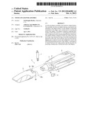
[0018] FIG. 1 is a perspective view depicting a tooth uncoupled from an adaptor that is mounted to a dipper bucket.
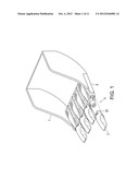
[0019] FIG. 2 is a perspective view depicting a tooth being seated on an adaptor mounted to a dipper bucket.
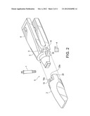
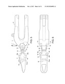
[0020] FIG. 3 is a side elevation view depicting the tooth and adaptor assembly of FIG. 1 with the tooth seated on the adaptor.
[0021] FIG. 4 is a top plan view depicting the tooth and adaptor assembly of FIG. 3.
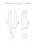
[0022] FIG. 5 is a side elevation view depicting the tooth and adaptor assembly of FIG. 1 with the tooth uncoupled from the adaptor.
[0023] FIG. 6 is a top plan view depicting the tooth and adaptor assembly of FIG. 5.
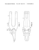
[0024] FIG. 7 is a left side elevation view depicting the tooth and adaptor assembly of FIG. 3 showing the internal features of the coupled tooth and adaptor in cross-hatch lines.
[0025] FIG. 8 is a top plan view depicting the tooth and adaptor assembly of FIG. 7.
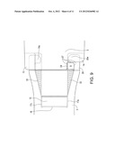
[0026] FIG. 9 is a close-up top plan view depicting the tooth and adaptor assembly of FIG. 8.
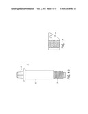
[0027] FIG. 10 is a side elevation view depicting a retainer pin for use with the tooth and adaptor assembly of FIG. 1.
[0028] FIG. 11 is a cross-section side elevation view depicting a nut for use with the retainer pin of FIG. 10.
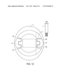
[0029] FIG. 12 is a cross-section front elevation view depicting the tooth and adaptor assembly of FIG. 3 along section lines X1-X1.
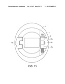
[0030] FIG. 13 is a cross-section front elevation view depicting the tooth and adaptor assembly of FIG. 12 with a retainer pin installed.
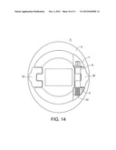
[0031] FIG. 14 is a cross-section front elevation view depicting the tooth and adaptor assembly of FIG. 13 with a nut threaded to the retainer pin.
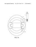
[0032] FIG. 15 is a cross-section front elevation view depicting an alternate embodiment of the tooth and adaptor assembly of FIG. 12.
DETAILED DESCRIPTION OF EMBODIMENTS
[0033] Referring to FIGS. 1 and 2, an embodiment of a tooth and adaptor assembly is shown. In some embodiments, tooth/adaptor assembly 5 can comprise of excavation tooth 2, adaptor 3, retainer pin 1 and retainer pin nut 4. Adaptor 3 can comprise elongated U-shaped member 6 that can attach to dipper bucket 7 on bucket lip 8, as well known to those skilled in the art. Tooth 2 can be seated onto adaptor 3 and secured by retainer pin 1 that can be installed into a retainer pin passageway formed when tooth 2 is seated on adaptor 3, and held in place by nut 4. Tooth 2 can be designed to bear the brunt of the wearing forces caused by excavating and will wear out over time. As tooth 2 wears out to the point that it is no longer serviceable, tooth 2 can be removed from adaptor 3 by unthreading retainer pin 1 from retainer pin nut 4. Retainer pin 1 can then be removed from retainer pin passageway 9, as illustrated in FIG. 4. Tooth 2 can then be removed from adaptor 3.
[0034] Referring to FIGS. 3 and 4, side and top views of assembly 5 is shown with tooth 2 fully seated on adaptor 3. In some embodiments, tooth 2 can comprise pointed tip 10 designed for excavating. As more clearly shown in FIGS. 13 and 14, tooth 2 can be secured to adaptor 3 with retainer pin 1 seated in retainer pin passageway 9, and threaded into retainer pin nut 4.
[0035] Referring to FIGS. 5 and 6, side and top views of assembly 5 is shown with tooth 2 uncoupled from adaptor 3. In some embodiments, adaptor 3 can comprise elliptical base portion 11 that can transition from elongated U-shaped member 6 to intermediate circular tapered cone portion 12 and from block portion 15. In some embodiments, block portion 15 can be rectangular in cross-section, although other cross-sectional shapes can be used as well known to those skilled in the art. In some embodiments, tapered cone portion 12 can comprise lug socket cavities 13 and 14, disposed on either side of tapered cone portion 12. In some embodiments, lug socket cavities 13 and 14 can be a continuation of opposing planar surfaces 25 and 26 disposed on the sides of tapered cone portion 12. In some embodiments, tooth 2 can comprise opposing sidewall leg extensions 19 and 20 extending therefrom, each comprising hooks 19a and 19b, and 20a and 20b, respectively, forming a groove therebetween. To couple tooth 2 to adaptor 3, tooth 2 can comprise socket 16 that is configured to receive front block portion 15, tapered cone portion 12 and elliptical base portion 11. Wedge portions 32 and 33 disposed on planar surfaces 25 and 26, respectively, can be configured to slide in the grooves defined by the hooks disposed on leg extensions 19 and 20. Load forces passing from adaptor 3 to tooth 2, and from tooth 2 back to adaptor 3, can be transmitted via the uniform mated surfaces disposed on tooth 2 and adaptor 3. In some embodiments, when tooth 2 is substantially seated on adaptor 3, retainer pin passageway 9 can be formed to provide a substantially vertical and continuous passageway for receiving retainer pin 1, as illustrated in FIGS. 8 and 9.
[0036] Referring to FIGS. 7 and 8, FIG. 7 illustrates an internal cross-section view of tooth 2 coupled on adaptor 3. FIG. 8 illustrates an internal cross-section top view of tooth 2 coupled on adaptor 3.
[0037] Tooth sidewalls 17a to 17d (in some embodiments, socket 16 can comprise a rectangular cross-section, with each sidewall disposed therein labelled as 17a through d, respectively) and primary thrust bearing surface 18 can provide an opening to receive front block 15 of adaptor 3 in a sliding fit. In some embodiments, tooth socket 16 can comprise tapered, elliptical and planar surfaces configured to substantially and uniformly mate to elliptical base portion 11, tapered cone portion 12 and front block 15. Tooth sidewall leg extensions 19 and 20 can uniformly seat into socket cavities 13 and 14, respectively, in a sliding fit.
[0038] FIG. 9 illustrates an enlarged top view of one embodiment of tooth and adaptor assembly 5, wherein retainer pin passageway 9 is formed when tooth 2 is fully seated on adaptor 3. In some embodiments, top surface 27 of passageway 9 can be formed by the combination of tooth sidewall leg extension 20, stepland 24 and leg hook 20a, as shown in FIGS. 9 and 12.
[0039] Referring to FIG. 10, one embodiment of retainer pin 1 is shown. In some embodiments, retainer pin 1 can comprise cylindrical body 22 with flanged head bolt head 21 disposed at an upper end thereof, and threaded end 23 disposed at a lower end thereof. Referring to FIG. 11, a cross-section view of one embodiment of threaded nut 4 is shown.
[0040] Referring to FIGS. 12 to 14, a cross-section view of tooth and adaptor assembly 5, as shown in FIG. 3, is illustrated. In FIG. 12, retainer pin 1 is shown about to be inserted in passageway 9. In FIG. 13, retainer pin 1 is inserted in passageway 9, wherein retainer pin 1 is adjacent to hooks 20a and 20b of leg extension 20 and positioned behind wedge portion 32, as shown in FIG. 9. In this configuration, retainer pin 1 prevents tooth 2 from being removed from adaptor 3. In FIG. 14, retainer pin nut 4 is shown threaded onto threaded end 23 of retainer pin 1 to secure it to tooth and adaptor assembly 5.
[0041] In FIG. 15, an alternate embodiment of tooth 2 is shown seated on adaptor 3. In this embodiment, tooth 2 can comprise threaded hole 34 integrated therein to receive threaded end 23 of retainer pin 1.
[0042] Although a few preferred embodiments have been shown and described, it will be appreciated by those skilled in the art that various changes and modifications might be made without departing from the scope of the invention. The terms and expressions used in the preceding specification have been used herein as terms of description and not of limitation, and there is no intention in the use of such terms and expressions of excluding equivalents of the features shown and described or portions thereof, it being recognized that the invention is defined and limited only by the claims that follow.
User Contributions:
Comment about this patent or add new information about this topic:
Images included with this patent application:
 |  |
 |  |
 |  |
 |  |
 |  |
 |  |
| Similar patent applications: | |
| Date | Title |
|---|---|
| 2008-08-28 | Tooth and adaptor assembly |
| 2009-12-31 | Tooth and adaptor for dredging machine |
| 2010-07-15 | Snowplow and mount assembly |
| 2012-09-06 | Work machine and mounting pin assembly |
| 2008-10-30 | Machine with automated blade positioning system |
| New patent applications in this class: | |
| Date | Title |
|---|---|
| 2016-06-23 | Ground engaging tool |
| 2016-06-09 | Lock for ground engaging tool |
| 2016-06-09 | Ground engaging tool |
| 2016-04-28 | Retention system having double-ended expandable pin |
| 2016-02-25 | Reliable connection system and assemblies and methods for using the reliable connections |
| New patent applications from these inventors: | |
| Date | Title |
|---|---|
| 2009-02-19 | Retainer pin and tooth for tooth and adaptor assembly |
| Top Inventors for class "Excavating" | |
| Rank | Inventor's name |
|---|---|
| 1 | James Robert Lahood |
| 2 | Phillip J. Kunz |
| 3 | Robert N. Gamble, Ii |
| 4 | Mark D. Buckbee |
| 5 | Kent Winter |