Patent application title: SINGLE ACTION REEL CONTROL MECHANISM
Inventors:
Tristan Christianson (San Francisco, CA, US)
Wing Yin Chung (Hong Kong, HK)
Assignees:
ABSOLUTELYNEW, INC.
IPC8 Class: AB65H7530FI
USPC Class:
2423961
Class name: Reeling device with brake positive
Publication date: 2012-09-20
Patent application number: 20120234959
Abstract:
A retractable reel rotational control apparatus, comprising a mechanical
actuator which simultaneously brakes and locks the reel in a single
action of the actuator, and releases the brake and lock with a subsequent
action, wherein the reel brake is separate from the actuator.Claims:
1. A retractable reel rotation control apparatus with a single
multifunction actuator comprising: a. A housing; b. An actuator; c. A
reel; d. A tension element furled and unfurled by said reel; e. A brake
connecting said actuator to said reel; f. A tracing groove to regulate
the function of said actuator to said reel, where the tracing groove is
in the surface of the actuator; g. A tracing pin located between said
housing and said tracing groove, where one end of said pin is pivotally
mounted to said housing and the other end of said pin freely traces said
tracing groove.
2. A retractable reel rotational control apparatus of claim 1, wherein the housing comprises of two halves.
3. A retractable reel rotational control apparatus of claim 2, wherein the actuator is a trigger.
4. A retractable reel rotational control apparatus of claim 2, wherein the actuator is a button.
5. A retractable reel rotation control device with a single multifunction control device comprising: a. A housing; b. An actuator; c. A reel; d. A tension element furled and unfurled by said reel; e. A brake connecting said actuator to said reel; f. A tracing groove to regulate the function of said actuator to said reel, where the tracing groove is located on the housing of the rotational control device; g. A tracing pin located between said housing and said tracing groove, where one end of said pin is pivotally mounted to said housing and the other end of said pin freely traces said tracing groove.
6. A retractable reel rotational control device of claim 5, wherein the housing comprises of two halves.
7. A retractable reel rotational control device of claim 6, wherein the control device is a trigger.
8. A retractable reel rotational control device of claim 6, wherein the control device is a button.
Description:
CROSS-REFERENCE TO RELATED APPLICATIONS
[0001] U.S. Provisional Application 61/387,374.
FEDERALLY SPONSORED RESEARCH
[0002] Not Applicable.
SEQUENCE LISTING
[0003] None.
BACKGROUND OF THE PRESENT INVENTION
[0004] 1. Technical Field
[0005] The invention pertains to a retractable reel control mechanism in the handle of a retractable device such as a pet leash or tape measure, which allows for releasable movement of the reel containing the cord, tape or other flexible line material through a single action upon the reel without the need for a separate lock button.
[0006] 2. Prior Art
[0007] Most of the available rotational control devices in the market use a locking mechanism which requires two-step action before the locking mechanism is applied to the leash: the user needs to activate the brake key, followed by the brake lock in order to lock the reel.
[0008] One disadvantage of traditional retractable reel assemblies is that the switching mechanism for selecting between a spring-loaded tension mode and a locked mode of operation is somewhat clumsy to operate due to multiple steps required to shift from one function to the other.
[0009] U.S. Pat. No. 6,648,261 discloses an extendible and retractable lead that can be extended or retracted and locked in position in a single action. The single action feature is attained by means of a moveable member extending from the exterior of the casing into the interior thereof, and the interior part of the moveable member engages with a retainer in the form of a resiliently deformable latch in the form of a living hinge.
[0010] U.S. Pat No. 7,784,728 discloses a rotational control device comprises a locking and unlocking button. While this invention improves the convenience of having a separate button for locking and unlocking functions, the invention still requires two buttons for each of the actions to the reel.
[0011] Accordingly, a need remains for an improved locking mechanism in order to overcome such shortcomings in reel control devices, including means to allow for the lock and release of a retractable device in a more efficient single motion.
OBJECTS OF THE INVENTION
[0012] The main object of the invention is to apply the intuitive operation of a trigger mechanism to the retractable device design, resulting an improved brake mechanism compared to the prior art that is safer and convenient to use.
SUMMARY OF THE INVENTION
[0013] The invention remedies deficiencies in conventional reel control mechanism by providing in one embodiment a reel control device comprising a housing, a reel assembly, a reel brake, a tension element, an actuator, a track groove to regulate the function of said actuator to said reel, and a tracing pin located between said housing and said track groove, inserted into said track groove.
[0014] The actuator is defined as an interface device between the user and the reel. In one embodiment of the invention, the actuator is shaped as a trigger. However, the actuator can be shaped as a button on an alternative embodiment of the invention, and any person skilled in the art will be able to implement different variations of the actuator that performs the same task of being the interface device between the user and the reel.
[0015] Unlike the prior art, where the brake key and the brake lock are two separate actions using the thumb/finger, the present invention combines both actions into a single action on the actuator. This has several advantages: (1) A single motion on the actuator is a far more intuitive and simpler action than several motions of the thumb in order to achieve the same result, (2) the mechanism eliminates the need to manually lock the brake, since the majority of rotational control involve both braking and locking in the same instance.
[0016] Another unique feature present in the current invention is having a brake that is a separable piece from the actuator, such that when the user activates the control through the actuator, the resulting force feedback from the brake stopping the reel is not directly channeled through the actuator in a one piece design. This results in more smooth action between the actuator, the brake and the reel while retaining instantaneous communication between the actuator, brake and reel when the user manipulates the actuator.
DRAWINGS
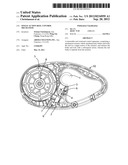
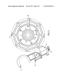
[0017] FIG. 1 shows a vertical cutaway seen from the left hand side of an embodiment according to the invention in the form of a pet leash assembly, with the actuator at the "free" or ready position;
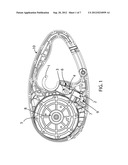
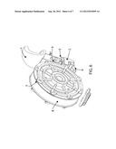
[0018] FIG. 2 shows a vertical cutaway seen from the left hand side of an embodiment according to the invention in the form of a pet leash assembly, with the actuator at the locked position;
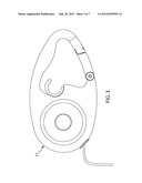
[0019] FIG. 3 shows a side elevation of an embodiment of the invention in the form of a pet leash assembly embodiment having an unwinding arrangement for an animal leash;
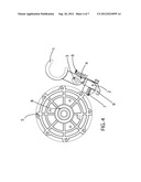
[0020] FIG. 4 shows a vertical cutaway of only the actuator mechanism seen in FIG. 1, seen from the left hand side of the assembly.
[0021] FIG. 5 shows a vertical cutaway of only the actuator mechanism seen in FIG. 4, seen from the right hand side of the assembly.
[0022] FIG. 6 shows an isometric view seen from the front left side of the actuator mechanism seen in FIG. 1.
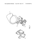
[0023] FIG. 7 shows a disassembled isometric view of only the actuator mechanism seen in FIG. 4.
REFERENCE NUMERALS
[0024] 1 actuator
[0025] 2 brake
[0026] 3 tracing pin
[0027] 4 tracing groove
[0028] 5 reel teeth
[0029] 6 actuator compression spring
[0030] 7 brake compression spring
[0031] 8 reel
[0032] 9 actuator rail
[0033] 10 handle
[0034] 11 housing
DETAILED DESCRIPTION OF THE PREFERRED EMBODIMENT
[0035] FIG. 1 is a perspective view take from the user's left side of the inside of the retractable device at ready state where the reel is free to rotate. The actuator 1 is located at the handle 10 where the user would wrap his or her hand on the leash handle. Within the actuator a uniquely shaped tracing groove 4 is molded, and a tracing pin 3 is aligned within the track rail, at the ready position. Resting on the actuator is a brake 2, held in place by a compression spring 7. Another compression spring 6 is situated parallel to the trigger to hold the actuator in place and to hold the trigger at its designated positions.
[0036] FIG. 2 uses the same perspective from FIG. 1, with the actuator at its locked state. Here actuator 1 is slightly displaced from the ready state seen in FIG. 1, tracing pin 3 is located at the locked position in the tracing groove 4, locking the entire mechanism in this current state. Brake 2 is in locking position, coming to full contact with one of the reel teeth 5. Both compression spring 6 and compression spring 7 are in compressed state.
[0037] FIG. 7 shows a disassembled vertical cross-section view of the trigger mechanism, revealing the actuator rail 10 that pushes brake 2 toward the reel teeth when actuator 1 is pulled once from the ready state shown in FIG. 1.
[0038] Operation of the reel control mechanism can be split into two distinctive actions. The first action is when the actuator is pulled from its ready position. Pulling the actuator when it is at its ready position will result in simultaneously braking and locking the leash.
[0039] When the user pulls the actuator 1 from the ready position, actuator 1 gets pulled toward the user in a linear fashion. As the actuator 1 gets displaced from its original position, the rail portion of the actuator 1 travels along the brake 2, pushing the brake 2 toward the reel 8 as the angled portion of the actuator rail 9 travels on the brake. The brake 2 then moves toward the reel, catching a tooth 5 on the reel 8 and stops the rotational motion of the reel. The actuator's 1 overall motion is regulated by a system comprising a tracing pin 3 that is mounted on the housing, and a uniquely shaped tracing groove 4 upon which the tracing pin 3 travels. The tracing pin 3 is mounted such that it can only travel by rotating in a small arc, roughly perpendicular to the motion of the actuator 1. As a result of the displacement of the actuator 1, the tracing pin 3 is forced to move along the tracing groove 4 until it reaches the locked position, a ridge at which the tracing pin 3 will latch and lock in position until the next actuator 1 pull. The tracing pin 3 is locked in position due to tension resulting from a compression system 6 mounted parallel to actuator 1 within the housing. The leash is now locked as shown on FIG. 2 until actuator 1 is pulled again.
[0040] The second action of the mechanism is when pulling the actuator 1 from its locked position. Pulling actuator 1 from its locked position results in the brake 2 simultaneously disengaging from and unlocking the reel 8, and returning the actuator mechanism to its ready position.
[0041] The mechanism of the second action goes as follows: User pulls actuator 1 from the locked position. Actuator 1 gets pulled toward the user in a linear fashion, identical to the first action. Displacement of actuator 1 also results in a simultaneous displacement of the tracing pin 3 from its locked position, forcing the tracing pin 3 to travel along the tracing groove 4 until it reaches its ready position, while the actuator moves back to its ready state. At the same time actuator 1 gets pulled and displacing itself to the ready position, the displacement of actuator 1 moves the actuator rail 9 from the brake 2, resulting in the brake 2 returning to its ready state with the assistance of a compressed spring 7, recoiling back to the ready state shown in FIG. 1.
[0042] Although the drawings depict the invention of the reel rotational control device embodied in a dog leash, one skilled in the art will readily see other applications for the mechanism in various tools, toys and the like, such that the embodiment of the present invention as shown in the drawings and described above is exemplary only and not intended to be limiting.
User Contributions:
Comment about this patent or add new information about this topic:
Images included with this patent application:
 |  |
 |  |
 |  |
 |  |
| Similar patent applications: | |
| Date | Title |
|---|---|
| 2009-12-17 | Multiple attitude low paper sensor mechanism |
| 2011-01-20 | Dual-bearing reel lever drag mechanism |
| 2012-03-22 | Dual-bearing reel clutch control device |
| 2011-12-15 | Automatic banner roll-up mechanism |
| 2009-01-01 | Laying reel for coiling rolled wire |
| New patent applications in this class: | |
| Date | Title |
|---|---|
| 2015-01-15 | Closure devices including incremental release mechanisms and methods therefor |
| 2013-06-27 | Spool assembly with locking mechanism for additive manufacturing system, and methods of use thereof |
| 2013-02-28 | Sensor assembly for a vehicle occupant protection device |
| 2013-02-21 | Interlock system |
| 2011-02-03 | Locking spool for telecommunications cable and method |
| New patent applications from these inventors: | |
| Date | Title |
|---|---|
| 2014-02-27 | Holder for flexible sheet material |
| 2012-12-20 | Tug toy with hand guard |
| 2012-11-15 | Bird feeder |
| 2012-04-12 | Interactive feline toy |
| 2012-03-29 | Height adjustable pillow |
| Top Inventors for class "Winding, tensioning, or guiding" | |
| Rank | Inventor's name |
|---|---|
| 1 | Masaru Ukita |
| 2 | Wataru Yanagawa |
| 3 | Akira Niitsuma |
| 4 | Akira Sumiyashiki |
| 5 | Yoshiaki Maekubo |