Patent application title: Cushioning Foot for Cane, Crutch, or Walking Aid
Inventors:
Allen Zadeh (Brooklyn, NY, US)
Allen Zadeh (Brooklyn, NY, US)
Rie Norregaard (New York, NY, US)
Clay Allen Burns (New York, NY, US)
Assignees:
OMHU, INC.
IPC8 Class: AA45B904FI
USPC Class:
135 82
Class name: Canes, sticks, crutches, and walking aids tips shock absorbing
Publication date: 2012-08-23
Patent application number: 20120211036
Abstract:
A cushioning foot for a mobility aid includes an elastomeric or rubber
foot configured to compress under axial and angular loading. A collar is
affixed to the distal end of a shaft of the mobility aid and includes a
flange for contacting and compressing the elastomeric or rubber foot
under axial and angular loads.Claims:
1. A foot for canes, crutches, or walkers in which a load bearing
circular flange is positioned near the distal end of an axial shaft, said
flange imparting a force to the cylindrical walls of said foot thereby
providing improved shock absorption.
2. The foot of claim 1 in which said foot is made from a medium to soft elastomeric or rubber material.
3. The foot of claim 2 in which an abrasion-resistant elastomeric or rubber tread surface is affixed to the bottom of the foot.
4. The foot of claim 1 in which said foot is made from a medium to high durometer abrasion-resistant material.
5. The foot of claim 1 in which said flange is part of a cup-shaped collar that affixes to the distal end of the shaft.
6. The foot of claim 5 in which the bottom of the collar provides a closed surface at the end of the shaft.
7. The foot of claim 6 in which said closed surface is domed or flat.
8. The foot of claim 5 in which there is a vertical gap between said closed surface and the inner surface of the foot, so as to allow vertical travel between the collar and the inside surface of the foot.
9. The foot of claim 1 in which said foot is an inverted truncated cone shape.
Description:
[0001] This application claims the benefit of U.S. Provisional Application
No. 61/375,945 filed Aug. 23, 2010, which is incorporated herein by
reference.
FIELD OF THE DISCLOSURE
[0002] The present disclosure relates generally to walking aids, and more particularly to a cushioning foot for a walking aid such as a cane, crutch, or similar mobility aid.
BACKGROUND
[0003] Many people require devices to aid their mobility. Mobility devices such as canes, crutches, or walking aids may be used by people to assist in their movement.
SUMMARY
[0004] The present disclosure pertains to a foot for mobility aids such as canes, crutches, or walkers. In one embodiment, a load bearing circular flange is positioned near the distal end of an axial shaft. The flange imparts a force to the cylindrical walls of the foot thereby providing improved shock absorption.
[0005] The foot can be made of a medium to soft elastomeric or rubber material. An abrasion-resistant elastomeric or rubber tread surface can be affixed to the bottom of the foot. The foot can also be made from a medium to high durometer abrasion-resistant material. In one embodiment, the flange is part of a cup-shaped collar that affixes to the distal end of the shaft. The bottom of the collar can be a closed surface at the end of the shaft. The closed surface can be domed or flat. In one embodiment, a vertical gap between the closed surface and the inner surface of the foot allows vertical travel between the collar and the inside surface of the foot. In one embodiment, the foot is an inverted truncated cone shape.
[0006] These and other advantages of the invention will be apparent to those of ordinary skill in the art by reference to the following detailed description and the accompanying drawings.
BRIEF DESCRIPTION OF THE DRAWINGS
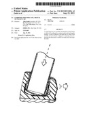
[0007] FIG. 1 depicts a cane foot according to one embodiment;
[0008] FIG. 2 depicts a cross-section of the cane foot shown in FIG. 1;
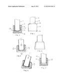
[0009] FIG. 3 depicts a cane foot under compression with a force applied;
[0010] FIG. 4 depicts a cane foot under varied compression with an angular force applied;
[0011] FIG. 5 depicts a cane foot according to another embodiment; and
[0012] FIG. 6 depicts a cane foot according to yet another embodiment.
DETAILED DESCRIPTION
[0013] FIG. 1 shows a novel cane foot. FIG. 2 shows a cross-section of the novel cane foot shown in FIG. 1. Load bearing cup-shaped collar 12 is attached to the distal end of shaft 11. Said collar is advantageously made of metal similar to that of the shaft, such as aluminum 6063 or 6061. In one embodiment, collar 12 is affixed to shaft 11 using a tight press fit or an adhesive, although other means may be used. For example, flange 13 of collar 12 may be made as part of the shaft with a special forming process, or it may be affixed as a ring with no bottom using an adhesive or fasteners such as rivets. The distance from the bottom of flange 13 to the distal end of the shaft is designed to approximately match the inner depth of elastomeric foot 14. In an advantageous embodiment, this distance is 1 to 1.5 inches.
[0014] Cup-shaped elastomeric foot 14 is pressed onto the distal end of collar 12 and shaft 11 such that the friction of said foot 14 provides a suitable attachment. Alternately, in an advantageous embodiment, collar 12 includes a bulge 15 to further secure foot 14. Other attachment aids are possible. For example, an attachment aid may be the use of a ridge, knurl, or adhesive.
[0015] When force is applied to the foot, such as when a person presses his or her weight onto the cane with the cane touching the ground, the top surface of foot 14 bears against the lower surface of flange 13, compressing the outer walls of foot 14 into a barrel shape, shown in FIG. 3. This compression uses the cushioning ability of the cylindrical portion of foot 14, in addition to the usual cushioning attained by the distal end of the shaft striking inner surface 17 of foot 14. In an advantageous embodiment, inner surface 17 is lower than the distal end of shaft 11 and collar 12 by 1-2 mm. This gap allows the distal end of shaft 11 and collar 12 to move axially under normal loads, and to impact surface 17 under heavy loads, so that the entire foot provides cushioning function. This design further allows for varied compression around the cylinder of foot 14 when an angular force is applied, as shown in FIG. 4. Angular forces are very common in the use of canes, walkers and crutches, and it is crucial that the cane foot allow for excellent traction under these situations, so as to prevent the mobility aid from slipping out from under the user.
[0016] Foot 14 is made from an elastomeric or rubber material that is resilient and of medium to soft durometer. This provides improved shock absorption over standard crutch foot material, which is often of a harder durometer for wear-resistance. In an advantageous embodiment, tread 16 is bonded to or co-molded with foot 14 to provide a long-wearing and high-traction surface for the foot where it meets the ground or walking surface. This combination gives the foot both shock-absorbing and durable grip and wear in a simple compact design.
[0017] In an advantageous embodiment, tread 16 is made from a different color than foot 14 to demonstrate the functionality and to allow the user to observe when the tread is worn. Alternatively, tread 16 and foot 14 can be the same color. Further, tread 16 could be eliminated if foot 14 is made from a medium to high durometer material with good abrasion resistance, however, while the barrel-like shock-absorbing feature will still exist, the cushioning feel will be reduced.
[0018] FIG. 5 shows an alternative embodiment, in which metal cup 12 does not include a bulge, and foot 14 is attached by means of friction, using a compressive fit over cup 12. Further, cup 12 in this embodiment uses a flat bottom with large radii, rather than a dome. The cushioning action is still provided by means of the gap between the bottom of cup 12 and the inside surface of foot 14.
[0019] The outer perimeter of foot 14 may have different shapes at rest, while still providing the function described. One such embodiment is shown in FIG. 6, which depicts a truncated inverted cone shape. Numerous other shapes are possible as well.
[0020] The foregoing Detailed Description is to be understood as being in every respect illustrative and exemplary, but not restrictive, and the scope of the invention disclosed herein is not to be determined from the Detailed Description, but rather from the claims as interpreted according to the full breadth permitted by the patent laws. It is to be understood that the embodiments shown and described herein are only illustrative of the principles of the present invention and that various modifications may be implemented by those skilled in the art without departing from the scope and spirit of the invention. Those skilled in the art could implement various other feature combinations without departing from the scope and spirit of the invention.
User Contributions:
Comment about this patent or add new information about this topic:
Images included with this patent application:
 |  |
| Similar patent applications: | |
| Date | Title |
|---|---|
| 2012-09-13 | Cloth cushion accessory for a crutch |
| 2009-10-29 | Crutch cushion, crutch system and kit |
| 2009-07-02 | Mono-crutch for lower leg disability |
| 2008-12-04 | Folding windscreen for ice fishing |
| 2010-06-17 | Adjustable lighted walking aid |
| New patent applications in this class: | |
| Date | Title |
|---|---|
| 2014-11-13 | Walking stick with s-shaped flexure mechanism to store and release energy |
| 2014-10-02 | Shock absorbing crutch tip and method of manufacture |
| 2014-07-03 | Force absorbing device |
| 2013-10-10 | Shock absorber insert for a walking aid |
| 2013-08-15 | Walking aid with support |
| New patent applications from these inventors: | |
| Date | Title |
|---|---|
| 2015-11-26 | Light therapy platform system |
| 2015-11-26 | Light therapy platform system |
| 2015-11-26 | Light therapy platform system |
| 2015-11-26 | Light therapy platform system |
| 2015-11-26 | Light therapy platform system |
| Top Inventors for class "Tent, canopy, umbrella, or cane" | |
| Rank | Inventor's name |
|---|---|
| 1 | Oliver Joen-An Ma |
| 2 | Mark C. Carter |
| 3 | Wanda Ying Li |
| 4 | Wanda Ying Li |
| 5 | Kendyl A. Roman |