Patent application title: FIXING DEVICE FOR CIRCUIT BOARD
Inventors:
Chieh-Hsiang Lin (Tu-Cheng, TW)
Chieh-Hsiang Lin (Tu-Cheng, TW)
Wen-Tang Peng (Tu-Cheng, TW)
Assignees:
HON HAI PRECISION INDUSTRY CO., LTD.
IPC8 Class: AH05K714FI
USPC Class:
24822214
Class name: Specially mounted or attached interlocked bracket and support latch, retainer, or keeper is threaded member (i.e., set screw or locknut)
Publication date: 2012-07-05
Patent application number: 20120168584
Abstract:
A fixing device for circuit boards with different thickness includes a
base board, a number of posts, and a number of fasteners extending
through the circuit board and engaging with the posts. A number of fixing
holes are defined in the base board. Each post includes a first threaded
portion and a second threaded portion selectively screwed in the
corresponding fixing holes of the base board. The length of the second
threaded portion is different from the length of the first threaded
portion.Claims:
1. A fixing device for circuit boards with different thickness, the
fixing device comprising: a base board defining a fixing hole; a post
comprising a first threaded portion and a second threaded portion to be
selectively screwed in the fixing hole of the base board, wherein the
lengths of the first and the second portions are different; and a
fastener to extend through a circuit board and engage in the post via one
of the first threaded portion or the second threaded portion that is not
to be screwed in the fixing hole.
2. The fixing device of claim 1, further comprising a nut mounted to the base board through the fixing hole, wherein the nut axially defines a threaded hole extending through opposite sides of the nut to selectively receive the first or the second threaded portion of the post.
3. The fixing device of claim 2, wherein the nut comprises a protrusion engaging in the fixing hole of the base board, and a washer located above the base board, the threaded hole extends through the washer and the protrusion.
4. The fixing device of claim 1, wherein a threaded hole extending through the first and second threaded portions is defined in post to engage with the fastener.
5. The fixing device of claim 1, wherein the first and second threaded portions of the post each define a threaded hole to engage with the fastener.
6. The fixing device of claim 1, wherein the fastener is a screw.
7. The fixing device of claim 1, wherein the post further comprises a main body, the first and second threaded portions extend from opposite ends of the main body.
8. The fixing device of claim 7, wherein the main body is hexagon-shaped in cross section.
9. A fixing device for circuit boards with different thicknesses, comprising: a base board defining four fixing holes; four posts each comprising a first threaded portion and an opposite second threaded portion to be selectively screwed in a corresponding one of the four fixing holes of the base board, wherein the lengths of the first and the second portions are different; and four fasteners, each to extend through a circuit board and engage in a corresponding one of the four posts via one of the first threaded portion or the second threaded portion of the corresponding post that is not to be screwed in the corresponding fixing hole.
10. The fixing device of claim 10, further comprising four nuts, wherein each nut is mounted to the base board through a corresponding one of the four fixing holes, and each nut axially defines a threaded hole extending through opposite sides of the nut to selectively receive the first or the second threaded portion of the corresponding post.
Description:
CROSS-REFERENCE OF RELATED APPLICATIONS
[0001] Relevant subject matter is disclosed in two pending U.S. patent applications, both titled with "FIXING DEVICE FOR CIRCUIT BOARD", respectively filed on May 25, 2011, with the application Ser. No. 13/115,121, and filed on May 27, 2011, with the application Ser. No. 13/117,140, which are assigned to the same assignee as this patent application.
BACKGROUND
[0002] 1. Technical Field
[0003] The present disclosure relates to an adjustable device for fixing a circuit board.
[0004] 2. Description of Related Art
[0005] A circuit board is fixed to a computer chassis through a number of supporting posts. When there is a need to install another circuit board having a different thickness, the supporting posts should be replaced with others. However, in most cases, the supporting posts are an integral part of the chassis, which makes replacement very difficult, if not impossible.
BRIEF DESCRIPTION OF THE DRAWINGS
[0006] Many aspects of the present embodiments can be better understood with reference to the following drawings. The components in the drawings are not necessarily drawn to scale, the emphasis instead being placed upon clearly illustrating the principles of the present embodiments. Moreover, in the drawings, all the views are schematic, and like reference numerals designate corresponding parts throughout the several views.
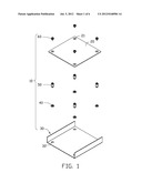
[0007] FIG. 1 is an exploded, isometric view of an exemplary embodiment of a fixing device, together with a circuit board; the fixing device includes a plurality of nuts.
[0008] FIG. 2 is a partial, enlarged view of FIG. 1.
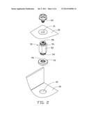
[0009] FIG. 3 is an enlarged, inverted view of one of the nuts of FIG. 1.
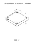
[0010] FIG. 4 is an assembled, isometric view of FIG. 1.
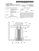
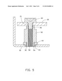
[0011] FIG. 5 is a sectional view of FIG. 4, taken along the line of V-V.
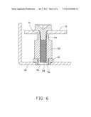
[0012] FIG. 6 is a sectional view of the fixing device of FIG. 1 fixing another circuit board.
DETAILED DESCRIPTION
[0013] The disclosure, including the accompanying drawings, is illustrated by way of example and not by way of limitation. It should be noted that references to "an" or "one" embodiment in this disclosure are not necessarily to the same embodiment, and such references mean at least one.
[0014] Referring to FIGS. 1 and 2, an exemplary embodiment of a fixing device 10 for fixing different circuit boards includes a base board 30, a plurality of nuts 40, a plurality of posts 50, and a plurality of fasteners 60. In this embodiment, the fasteners 60 are screws.
[0015] In one embodiment, the base board 30 is a sidewall of a computer enclosure, or a board fixed to the sidewall of the computer enclosure. A plurality of fixing holes 32 is defined in the base board 30.
[0016] Each post 50 includes a main body 52 with a hexagon-shaped cross section, and a first threaded portion 54 and a second threaded portion 56 extending from opposite ends of the main body 52. Threads are formed on the circumferences of the first and second threaded portions 54 and 56. The post 50 axially defines a threaded hole 58 extending through the first and second threaded portions 54 and 56. The length of the second threaded portion 56 is greater than the length of the first threaded portion 54.
[0017] Referring to FIG. 3, each nut 40 includes a round washer 42 and a protrusion 44 coaxially extending from a side of the washer 42. The diameter of the protrusion 44 is less than the diameter of the washer 42. The nut 40 axially defines a threaded hole 46 extending through the washer 42 and the protrusion 44.
[0018] Referring to FIGS. 4 and. 5, in assembly, the nuts 40 are fixed to the base board 30, and the protrusions 44 are respectively fixed in the corresponding fixing holes 32. The washers 42 are blocked by an inner surface of the base board 30.
[0019] To fix a first circuit board 20 defining a plurality of through holes 21, the first threaded portions 54 of the posts 50 are screwed into the threaded holes 46 of the corresponding nuts 40. The circuit board 20 is supported on distal ends of the second threaded portions 56, with the through holes 21 in an alignment with the threaded holes 58. The fasteners 60 extend through the fixing holes 21, and screw into the corresponding threaded holes 58, to fix the circuit board 20 to the base board 30.
[0020] Referring to FIG. 6, to fix a second circuit board 70 defining a plurality of through holes 71 and having less thickness than the first circuit board 20, the second threaded portions 56 are screwed into the threaded holes 46 of the corresponding nuts 40. The circuit board 70 is supported on the first threaded portions 54, with the through holes 71 in an alignment with the threaded holes 58. The fasteners 60 extend through the through holes 71, and screw into the corresponding threaded holes 58, to fix the circuit board 70 to the base board 30.
[0021] In other embodiments, the nuts 40 may be omitted to save cost, and threads are formed on an inner wall bounding each fixing hole 32 to fix a corresponding post 50.
[0022] In other embodiments, the two threaded holes, which do not communicate with each other, are respectively defined in the first and second threaded portions 54 and 56.
[0023] It is believed that the present embodiments and their advantages will be understood from the foregoing description, and they will be apparent that various changes may be made thereto without departing from the spirit and scope of the description or sacrificing all of their material advantages, the examples hereinbefore described merely being exemplary embodiments.
User Contributions:
Comment about this patent or add new information about this topic:
Images included with this patent application:
 |  |
 |  |
 |  |
 |
| Similar patent applications: | |
| Date | Title |
|---|---|
| 2014-01-16 | Installation device for instrumentation device of stationary engine |
| 2014-01-16 | Device for transmitting or decoupling mechanical vibrations |
| 2014-01-16 | Mounting assembly with automatic activation for alarm units |
| 2014-01-16 | Joint mechanism and supporting device therewith |
| 2010-07-08 | Caddy for car dashboard |
| New patent applications in this class: | |
| Date | Title |
|---|---|
| 2016-04-21 | End clip for recessed rail |
| 2015-03-26 | Folded beam clamp |
| 2014-12-25 | Mounting bracket |
| 2014-10-16 | Fixing plate |
| 2014-07-31 | Shadow skull mounting apparatus |
| New patent applications from these inventors: | |
| Date | Title |
|---|---|
| 2013-12-26 | Fastening device for hard disk drive |
| 2013-12-26 | Fastening device for hard disk drive |
| 2013-11-28 | Power distribution unit and server cabinet with the power distribution unit |
| 2013-10-03 | Server assembly with removable server module |
| 2013-06-27 | Server assembly and rack of the same |
| Top Inventors for class "Supports" | |
| Rank | Inventor's name |
|---|---|
| 1 | Jeffrey D. Carnevali |
| 2 | Yun-Lung Chen |
| 3 | Wen-Tang Peng |
| 4 | Zheng-Heng Sun |
| 5 | Zhan-Yang Li |