Patent application title: BOTTOM POURING NOZZLE FOR USE IN A CONTAINER FOR METAL MELTS
Inventors:
Francis Dams (Kessel-Lo, BE)
Martin Kendall (Zonhoven, BE)
Assignees:
HERAEUS ELECTRO-NITE INTERNATIONAL N.V.
IPC8 Class: AB22D3700FI
USPC Class:
222590
Class name: Dispensing processes of dispensing molten metal
Publication date: 2012-03-08
Patent application number: 20120055958
Abstract:
A pouring nozzle is provided for use in a container for metal melts. The
pouring nozzle has an inner wall surrounding a through-flow opening for
metal melts and an outer housing. During operation of the pouring nozzle
a pressure of at maximum 500 mbar exists between the inner wall and the
outer housing.Claims:
1.-9. (canceled)
10. A pouring nozzle for use in a container for metal melts, the pouring nozzle comprising an inner wall surrounding a through-flow opening for metal melts and an outer housing, wherein during operation of the pouring nozzle a pressure of at maximum 500 mbar exists between the inner wall and the outer housing.
11. The pouring nozzle according to claim 10, wherein the pressure is at maximum 400 mbar.
12. The pouring nozzle according to claim 10, wherein the pressure at maximum 300 mbar.
13. The pouring nozzle according to claim 10, wherein the pressure is 100 to 400 mbar.
14. The pouring nozzle according to claim 10, wherein the pressure is 250 to 300 mbar.
15. The pouring nozzle according to claim 10, further comprising a pump for generating the pressure.
16. A pouring device having a container for metal melts, wherein the pouring nozzle according to claim 10 is arranged in a wall of the container.
17. A method of operating a pouring nozzle for a metallurgical vessel having an inner wall surrounding a through-flow opening for metal melts and an outer housing, the method comprising operating the pouring nozzle by generating a pressure of at maximum 500 mbar between the inner wall and the outer housing.
18. The method according to claim 17, wherein the pressure is generated at a maximum 400 mbar.
19. The method according to claim 17, wherein the pressure is generated at a maximum 300 mbar.
20. The method according to claim 17, wherein the pressure is generated at 100 to 400 mbar.
21. The method according to claim 17, wherein the pressure is generated at 250 to 300 mbar.
22. The method according to claim 17, wherein the pressure is generated with help of a pump.
Description:
CROSS-REFERENCE TO RELATED APPLICATIONS
[0001] This application is a Section 371 of International Application No. PCT/EP2010/002443, filed Apr. 21, 2010, which was published in the German language on Nov. 18, 2010, under International Publication No. WO 2010/130330 A1 and the disclosure of which is incorporated herein by reference.
BACKGROUND OF THE INVENTION
[0002] The invention relates to a bottom pouring nozzle for use in a container for metal melts, having an inner wall surrounding a through-flow opening for metal melts, and an outer housing. Further, the invention relates to a method for operating the pouring nozzle, and to a pouring device for metal melts.
[0003] Such a pouring nozzle is well known in the prior art. For example, in Korean patent application publication no. KR 2003-0054769 the construction and operation of such a pouring nozzle are described. To prevent interruptions in the operation of the pouring nozzle, the pressure within the material of the pouring nozzle should be slightly reduced. Such pressure reductions of minus 1000 to minus 1300 mm H2O, in fact, are found in typical pouring nozzles of pouring equipment in the steel industry. They correspond to an absolute pressure of about 885 mbar to 915 mbar. In practice, it has been shown that with such resulting pressure decreases, which are almost inevitable, possibly due to the Venturi effect of the flowing metal melt, the problem of adhering of through-flowing material (so-called clogging) is eliminated only insufficiently. The adhering leads to a reduction in the diameter of the pouring nozzle, to a constantly changing flow rate, and thus to quality-lowering turbulences and gas entrapment in the metal melt.
[0004] Further pouring nozzles are known, for example, from German published patent application DE 10 2004 057 381 A1. Here, the attempt is made to avoid the problem of adhering (clogging) with the help of controlled inert gas addition or by complete sealing of the entire pouring nozzle and associated prevention of oxygen entrance through the wall of the pouring nozzle into the steel melt.
[0005] German Patent DE 198 47 271 C1 describes a method in which the described adhering should be avoided by adding particular slag formers to the molten steel. Here, foreign substances are thus introduced into the molten steel. The adherences are described as aluminum compounds forming in the molten steel.
BRIEF SUMMARY OF THE INVENTION
[0006] The object of the present invention is to provide a pouring nozzle which is improved in terms of adhering of material during through-flow and, at the same time, is largely simplified.
[0007] The object is achieved by a pouring nozzle for use in a container for metal melts, having an inner wall surrounding a through-flow opening for metal melts and an outer housing, wherein during operation of the pouring nozzle a pressure of at maximum 500 mbar exists between the inner wall and the outer housing. The object is further achieved by a method of operating the pouring nozzle for a metallurgical vessel having an inner wall surrounding a through-flow opening for metal melts and an outer housing, wherein during operation of the pouring nozzle a pressure of at maximum 500 mbar exists between the inner wall and the outer housing.
[0008] Surprisingly, it has been found that, even without a complete insulation of the pouring nozzle, the problem of adhering can be solved for the most part in that during operation of the pouring nozzle a pressure of at maximum 500 mbar exists between its inner wall and its outer housing. Preferably, the pressure is at maximum 400 mbar, in particular at maximum 300 mbar. Advantageously, to avoid clogging, the pressure ranges from 100 to 400 mbar, preferably from 250 to 300 mbar. Obviously, at such low pressure, a gas entrance into the through-flow opening of the pouring nozzle is effectively avoided, so that there is virtually no adhering of material on the wall of the through-flow opening while the material is flowing through. In addition, there is no gas contamination of the metal melt flowing through, in particular no contamination of a steel melt. The pouring rate is not lowered, turbulences in the melt are reduced. The required negative pressure can be generated preferably by conventional pumps.
[0009] Furthermore, according to the invention, a pouring device is equipped with a container for metal melts having a pouring nozzle, as described above, arranged in a wall, in particular in the floor (bottom) of the container.
[0010] The pouring nozzle may be equipped with an upper and a lower nozzle. The upper nozzle may be arranged directly in the wall of a pouring apparatus, while the lower nozzle is arranged below it. Between the two nozzles a slide valve, known in principle, may be arranged with whose help the through-flow opening can be opened or closed to regulate the flow of the metal melt.
[0011] Instead of a slide valve, a stopper rod can also be used in a known manner. By operation of the pouring nozzle is to be understood its operating state, that is, the state that exists during the through-flow of the metal melt. The pouring nozzle is preferably used for steel melts.
BRIEF DESCRIPTION OF THE SEVERAL VIEWS OF THE DRAWINGS
[0012] The foregoing summary, as well as the following detailed description of the invention, will be better understood when read in conjunction with the appended drawings. For the purpose of illustrating the invention, there are shown in the drawings embodiments which are presently preferred. It should be understood, however, that the invention is not limited to the precise arrangements and instrumentalities shown. In the drawings:
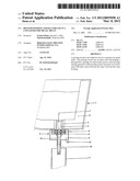
[0013] FIG. 1 is a side sectional view of a pouring device having a pouring nozzle according to one embodiment of the invention; and
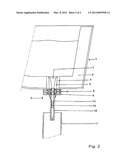
[0014] FIG. 2 is a side sectional view of a conventional pouring device having a bottom pouring nozzle.
DETAILED DESCRIPTION OF THE INVENTION
[0015] The pouring device 1 shown in FIG. 1 is, for example, a distributor of steel melts, in whose bottom a pouring nozzle 2 is arranged. The pouring nozzle 2 is inserted with its upper part 3 into seating stone 4, which is arranged in lining 5 of the distributor. Below the upper part 3 is arranged a so-called slide valve 6, by which through-flow opening 7 of the pouring nozzle 2 can be closed or opened. The slide valve 6 can be configured in a known manner. It is equipped with a push rod 8, which regulates the closure and which is guided in a sealed manner through the outer housing 9 of the pouring nozzle 2. The outer housing 9 surrounds the slide valve 8 and lies at its lower part sealed against the lower part 10 of the pouring nozzle 2. At its upper part housing 9 extends around the upper part 3 of the pouring nozzle 2, lies densely against the upper 3, and is surrounded on the outside by seating stone 4. The lower part 10 of the pouring nozzle 2 is arranged below the slide valve 6. It extends into mold 11. A vacuum pump is connected to an adjustable pump valve 12, by which the pressure between the outer housing 9 and the inner wall 13 bordering the through-flow opening 7 is lowered to a value of about 250 mbar. The pressure is measured in the pumping section.
[0016] Surprisingly, contrary to many experiences in current practice, it was found that no significant adhering on the inside of through-flow opening 7 could be found in the pouring nozzle 2 of the invention, even when the pressure is lowered to about 500 mbar.
[0017] FIG. 2 shows a pouring device without a significant reduction in pressure, which is generally similar to the arrangement shown in FIG. 1, but in which no pressure-reducing measures, in particular no housing and no vacuum pump, are present. This installation is operated at atmospheric pressure, thus at a pressure of about 1000 mbar.
[0018] It has been found that, in the arrangement shown schematically in FIG. 2, the described buildup 14 is formed in the interior of the lower part 10 of pouring nozzle 2, leading to irregular and constantly changing through-flow of molten steel. As a result, turbulences are generated, which can affect the quality of steel.
[0019] It will be appreciated by those skilled in the art that changes could be made to the embodiments described above without departing from the broad inventive concept thereof. It is understood, therefore, that this invention is not limited to the particular embodiments disclosed, but it is intended to cover modifications within the spirit and scope of the present invention as defined by the appended claims.
User Contributions:
Comment about this patent or add new information about this topic:
| People who visited this patent also read: | |
| Patent application number | Title |
|---|---|
| 20120058160 | PARTICULATE MATERIALS |
| 20120056871 | THREE-DIMENSIONAL IMAGING SYSTEM AND METHOD |
| 20120056870 | TIMING CONTROLLER, COLUMN DRIVER AND DISPLAY APPARATUS COMPRISING SAME |
| 20120056869 | ORGANIC LIGHT EMITTING DIODE DRIVER |
| 20120056868 | DRIVER FOR AN OLED DEVICE |
Images included with this patent application:
 |  |
 |
| Similar patent applications: | |
| Date | Title |
|---|---|
| 2009-04-09 | Method for preventing leaking of molten metal in injection molding of metal material |
| 2011-03-03 | Closures for plastic containers adapted for automated insert molding |
| 2011-07-28 | Actuator for spray container and method regarding same |
| 2010-11-11 | Fitment for connecting a container to a dispensing appliance |
| 2009-01-08 | Attachable spout for affixation to pouch-like container of liquid |
| New patent applications in this class: | |
| Date | Title |
|---|---|
| 2018-01-25 | System and method for transporting molen metal |
| 2016-03-31 | Method of transferring molten metal from a vessel |
| 2016-02-04 | Nozzle sand and method of use and operation |
| 2016-01-28 | Bottom-pouring-type ladle, and melt-pouring method using it |
| 2014-10-30 | Die casting nozzle and method for operating a die casting nozzle |
| New patent applications from these inventors: | |
| Date | Title |
|---|---|
| 2015-06-25 | Container for molten metal, use of the container and method for determining an interface |
| 2013-09-19 | Device for measuring temperature in molten metal |
| 2013-09-12 | Discharge nozzle for installation inside the base of a metallurgical vessel |
| 2012-06-07 | Method and apparatus for analyzing samples of metal melts |
| 2010-01-28 | Temperature measuring method in molten metal bath |
| Top Inventors for class "Dispensing" | |
| Rank | Inventor's name |
|---|---|
| 1 | Nick E. Ciavarella |
| 2 | John J. Mcnulty |
| 3 | Robert L. Quinlan |
| 4 | Andrew Jones |
| 5 | Heiner Ophardt |