Patent application title: WASTE HEAT BOILER
Inventors:
Thomas Paul Von Kossak-Glowczewski (Gummersbach, DE)
Cornelius Johannes Schellekens (Amsterdam, NL)
IPC8 Class: AC10J384FI
USPC Class:
122 7 R
Class name: Liquid heaters and vaporizers industrial waste heat
Publication date: 2012-01-26
Patent application number: 20120017853
Abstract:
Waste heat boiler (1) being an elongated vessel comprising a co-axial
positioned tubular channel (4) for hot gas, said channel further being
provided with an inlet (11) for hot gas and an outlet for cooled gas,
wherein a gas pathway (6) is defined between said inlet and outlet of
said tubular channel and wherein in the gas pathway one or more bundles
of tubular cooling surfaces are present, said tubular cooling surfaces
(7) positioned co-axial with the channel, wherein the tubular channel is
closed at one end (8), thereby forming a gas reversal chamber (9), and
wherein the gas inlet is an opening in the wall of the tubular channel
positioned between the gas reversal chamber and the gas pathway, wherein
the inlet for hot gas is connected to an inlet conduit (11), which
conduit is positioned under an angle α with said tubular channel
and wherein at the hot gas inlet in the tubular channel a diverter plate
(12) is present.Claims:
1. A waste heat boiler comprising an elongated vessel comprising a
co-axial positioned tubular channel for hot gas, said channel further
being provided with an inlet for hot gas and an outlet for cooled gas,
wherein a gas pathway is defined between said inlet and outlet of said
tubular channel and wherein in the gas pathway one or more bundles of
tubular cooling surfaces are present, said tubular cooling surfaces
positioned co-axial with the channel, wherein the tubular channel is
closed at one end, thereby forming a gas reversal chamber, and wherein
the gas inlet is an opening in the wall of the tubular channel positioned
between the gas reversal chamber and the gas pathway, wherein the inlet
for hot gas is connected to an inlet conduit, which conduit is positioned
under an angle α with respect to said tubular channel and wherein
at the hot gas inlet in the tubular channel a diverter plate is present.
2. A waste heat boiler according to claim 1, wherein the diverter plate is positioned under an angle β of between 5 and 45.degree. with respect to the longitudinal axis of the tubular channel.
3. A waste heat boiler according to claim 1, wherein the diverter plate is positioned under an angle β of between 10 and 25.degree. with respect to the longitudinal axis of the tubular channel.
4. A waste heat boiler according to claim 1, wherein the diverter plate is positioned under an angle β of 15.degree. with respect to the longitudinal axis of the tubular channel.
5. A waste heat boiler according to claim 1, wherein the diverter plate is positioned in the tubular channel such that two gas entry pathways are formed for the hot gas flowing towards the gas pathway, namely one via the gas reversal chamber and one via an opening directly connecting the gas inlet and the gas pathway.
6. A waste heat boiler according to claim 1, wherein the diverter plate is provided with cooling means.
7. A waste heat boiler according to claim 6, wherein the cooling means are one or more conduits having inlet and outlets for a cooling medium.
8. A waste heat boiler according to claim 2, wherein the angle β can be altered.
9. A waste heat boiler according to claim 1, wherein the diverter plate is provided with mechanical cleaning means.
10. A waste heat boiler according to claim 1, wherein a blaster is present to clean the diverter plate.
11. A waste heat boiler according to claim 1, wherein the surface of the diverter plate is provided with a layer of refractory or with cladding.
12. A waste heat boiler according to claim 5, further comprising two additional gas entry pathways, one on the left and one on the right of the diverter plate.
Description:
[0001] The invention is directed to a waste heat boiler for cooling a
solids laden hot gas.
[0002] Such a waste heat boiler is described in US-A-2006076272. This publication describes a typical coal gasification process as performed in an elongated gasification reactor vessel. The hot gas, as it is discharged by the gasification reactor, needs to be deflected by 180 degrees in order to flow downwards in the waste heat boiler. In the design of US-A-2006076272 the deflection of the hot gas is done via a bent duct section of about 45° with the horizon, followed by a gas reversal chamber in which the gas is deflected by 135°. The gas reversal chamber is present at the upper end of the waste heat boiler.
[0003] A disadvantage of the gasification configuration of the prior art design is that in operation solids may accumulate on the cooling surfaces and the support structure of the cooling surfaces as present in the waste heat boiler.
[0004] The present invention aims at providing an improved waste heat boiler. This is achieved by the following waste heat boiler.
[0005] Waste heat boiler being an elongated vessel comprising a co-axial positioned tubular channel for hot gas, said channel further being provided with an inlet for hot gas and an outlet for cooled gas, wherein
[0006] a gas pathway is defined between said inlet and outlet of said tubular channel and wherein in the gas pathway one or more bundles of tubular cooling surfaces are present, said tubular cooling surfaces positioned co-axial with the channel, wherein
[0007] the tubular channel is closed at one end, thereby forming a gas reversal chamber, and wherein the gas inlet is an opening in the wall of the tubular channel positioned between the gas reversal chamber and the gas pathway, wherein the inlet for hot gas is connected to an inlet conduit, which conduit is positioned under an angle α with said tubular channel and wherein
[0008] at the hot gas inlet in the tubular channel a diverter plate is present.
[0009] Applicants have found that by having such a plate present the gas flows more uniformly through the waste heat boiler. Because the gas velocities are more uniform almost no stagnant flow exists and therefore the solids do not have an opportunity to accumulate on the cooling surfaces and the support structure of the cooling surfaces and therefore, better heat transfer occurs.
[0010] The invention shall be further illustrated by making use of FIGS. 1-2.
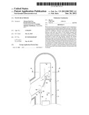
[0011] FIG. 1 shows the top end of a waste heat boiler according to the invention.
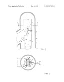
[0012] FIG. 2 shows cross-sectional view AA' of FIG. 1.
[0013] FIG. 1 shows the top end (1) of a waste heat boiler (2) being an elongated vessel (3). The vessel (3) comprises a co-axial positioned tubular channel (4) for hot gas. The channel (4) is provided with an inlet (5) for hot gas and an outlet for cooled gas at the lower end of the vessel (3) (not shown in this Figure). A gas pathway (6) is defined between said inlet (5) and outlet of said tubular channel (4). In the gas pathway (6) one or more bundles (7) of tubular cooling surfaces are present. The bundles (7) of tubular cooling surfaces are positioned co-axial with the channel. The tubular channel (4) is closed at one end (8), thereby forming a gas reversal chamber (9). The gas inlet (5) is an opening in the wall (10) of the tubular channel (4) positioned between the gas reversal chamber (9) and the gas pathway (6). The inlet (5) for hot gas is connected to an inlet conduit (11), which conduit is positioned under an angle α with said tubular channel (4). Angle α is preferably between 30 and 90°. At these preferred angles the hot gas as it flows, in use, through inlet conduit (11) will make a bend of more than 90° when it flows into the gas pathway (6). An example of the waste heat boiler (2) as described above is described in the aforementioned US-A-2006076272.
[0014] FIG. 1 also shows an additional diverter plate (12) at the hot gas inlet (5) in the tubular channel (4). Such a plate can advantageously be added to a waste heat boiler of US-A-2006076272 in order to improve the flow pattern by equalising the gas flow and thus increasing the heat transfer. With the phrase at the hot gas inlet (5) is meant: at the same elevation when the vessel (3) is positioned vertically, as will be the case when used for its intended application. In this manner at least some of the gas entering the tubular channel (4) will impinge on said diverter plate (12) when in use. The diverter plate (12) is preferably positioned under an angle β of between 5 and 45° with the longitudinal axis of tubular channel (4) with the top of the diverter plate rotated in the direction away from the flow of the incoming hot gas, as shown in FIG. 1. More preferably, the diverter plate (12) is positioned under an angle β of between 10 and 25°, and even more preferably, under an angle β of 15° with the longitudinal axis of tubular channel (4). In a preferred embodiment angle β can be altered. The plate preferably has a dimension and position in the tubular channel such that at least two main gas entry pathways (13 and 14) are formed for the hot gas flowing towards the gas pathway (6). Preferably four gas paths are formed. One main gas entry pathway (13) will run via the gas reversal chamber (9) and one main gas entry pathway will run via an opening (15) directly connecting the gas inlet (5) and the gas pathway (6). The two other gas paths (20a and 20b) are on the left and right side of the plate as shown in FIG. 2.
[0015] Preferably plate (12) is provided with cooling means. More preferably the cooling means are one or more conduits (16) having inlets (17) and outlets (18) for a cooling medium as shown in FIG. 2. A suitable cooling medium is chilled water or boiling water. Plate (12) is suitably supported by support rods (21). The support rods (21) are suitably fixed at the four edges of a, preferred rectangular, plate (12).
[0016] The plate (12) may suitably be provided with one or more mechanical cleaning means (19) or a blaster to remove any solids that may accumulate during operation. The surface of the plate (12) may suitably be provided with a layer of refractory or with cladding.
[0017] The uniformity of gas flow in waste heat boiler (2) was measured and analyzed with and without diverter plate (12). The velocity distribution of the gas was measured along a horizontal plane perpendicular to the bundles (7) of tubular cooling surfaces 0.5 meters above the bundles (7) of tubular cooling surfaces and along a horizontal plane perpendicular to the bundles (7) of tubular cooling surfaces 0.5 meters into the bundles (7) of tubular cooling surfaces.
[0018] The gas velocity distribution is best characterized by the standard deviation of the velocity magnitude or root mean square (RMS) of the velocity deviation from the average. RMS is a standard statistical method to evaluate how much a variable varies around its average value and is well known to those of ordinary skill in the art.
[0019] The RMS value of the gas velocity distribution at 0.5 meters above the top of bundles (7) of tubular cooling surfaces without the use of diverter plate (12) was 37.4% and with the use of diverter plate (12) positioned under an angle β of 20°, the RMS value was 5.2% and with the use of diverter plate (12) positioned under an angle β of 15°, the RMS value was 5.6%, both representing approximately a seven-fold improvement in gas velocity distribution versus the case where diverter plate (12) was not used.
[0020] The RMS value of the gas velocity distribution at 0.5 meters below the top of bundles (7) of tubular cooling surfaces without the use of diverter plate (12) was 8.5% and with the use of diverter plate (12) positioned under an angle β of 20°, the RMS value was 4.0%, and with the use of diverter plate (12) positioned under an angle β of 15°, the RMS value was 3.7%, both representing over a two-fold improvement in gas velocity distribution versus the case where diverter plate (12) was not used.
[0021] Thus, the use of the diverter plate (12) substantially increased the uniformity of gas velocity both above and within the bundles (7) of tubular cooling surfaces.
User Contributions:
Comment about this patent or add new information about this topic:
| People who visited this patent also read: | |
| Patent application number | Title |
|---|---|
| 20120164926 | GRINDING-SUPPORTING DEVICE |
| 20120164925 | SYSTEM FOR MAGNETORHEOLOGICAL FINISHING OF SUBSTRATES |
| 20120164924 | COMPOSITIONS AND METHODS FOR REMOVING SCRATCHES FROM PLASTIC SURFACES |
| 20120164923 | POLISHING METHOD |
| 20120164922 | METHOD FOR CLEANING A POLISHING PAD |
Images included with this patent application:
 |  |
| Similar patent applications: | |
| Date | Title |
|---|---|
| 2011-06-23 | Waste-heat boiler for partical-laden gases |
| 2009-04-02 | Water heaters with combustion air inlet |
| 2009-03-05 | Protection for heat transfer oil boiler |
| 2009-09-03 | Apparatus for the cleaning of high-pressure boilers |
| 2009-12-17 | Water heater with forced draft air inlet |
| New patent applications in this class: | |
| Date | Title |
|---|---|
| 2018-01-25 | Waste heat boiler |
| 2016-06-09 | A shell-and-tube apparatus for heat recovery from a hot process stream |
| 2015-12-17 | Multi-stage duct fired heat recovery steam generator and methods of use |
| 2015-04-23 | Recovery system of waste heat from flue gas |
| 2015-04-02 | System and method for drum level control in a drum of a heat recovery steam generator |
| New patent applications from these inventors: | |
| Date | Title |
|---|---|
| 2013-11-07 | Gasification reactor |
| 2013-08-08 | Tubular wall assembly and gasification reactor |
| 2012-12-06 | Heat exchanger and method of operating a heat exchanger |
| 2012-11-22 | Gasification reactor and process |
| 2012-06-07 | Heat exchanger |
| Top Inventors for class "Liquid heaters and vaporizers" | |
| Rank | Inventor's name |
|---|---|
| 1 | Jan Brückner |
| 2 | Joachim Franke |
| 3 | Hsing-Hsiung Huang |
| 4 | Hsin-Ming Huang |
| 5 | Martin Effert |