Patent application title: INFLATABLE THERMAL PACKAGING STRUCTURE WITH MULTIPLE LINERS
Inventors:
Alice K. Duong (San Diego, CA, US)
Assignees:
Coldpack, Inc.
IPC8 Class: AB65D8105FI
USPC Class:
206522
Class name: Special receptacle or package shock protection type (e.g., free fall) inflated retainer
Publication date: 2011-11-24
Patent application number: 20110284417
Abstract:
A packaging structure includes an outer shell and a first inflatable
liner attached to an interior surface of the outer shell. Air chambers of
the first inflatable liner are in fluid communication with a valve. The
packaging structure can also include a second inflatable liner attached
to the first liner. Air chambers of the second inflatable liner are in
fluid communication with the valve.Claims:
1. A packaging structure comprising: an outer shell; a first inflatable
liner attached to an interior surface of the outer shell, wherein air
chambers of the first inflatable liner are in fluid communication with a
valve; a second inflatable liner attached to the first inflatable liner,
wherein air chambers of the second inflatable liner are in fluid
communication with the valve.
2. The packaging structure of claim 1 wherein the outer shell is rigid.
3. The packaging structure of claim 1 wherein the outer shell comprises at least one of a cardboard or plastic material.
4. The packaging structure of claim 1 wherein the first inflatable liner comprises at least one of a nylon, or plastic material.
5. The packaging structure of claim 1 wherein the first inflatable liner comprises a plurality of heat seals defining the air chambers.
6. The packaging structure of claim 5 wherein the air chambers of the first inflatable liner are a single chamber having multiple sections.
7. The packaging structure of claim 1 wherein the first inflatable liner is attached to the interior surface of the outer shell using a plurality of glue strips.
8. The packaging structure of claim 1 wherein the second inflatable liner is attached to the first inflatable liner by at least one of tape of glue.
9. The packaging structure of claim 1 wherein the second inflatable liner is disposed inside the first inflatable liner upon inflation.
10. A method of forming a thermal structure, the method comprising: providing a packaging structure including an outer shell; flowing a fluid through a valve to inflate a first inflatable liner attached to an inner surface of the outer shell; and flowing the fluid through the valve to inflate a second inflatable liner attached to the first inflatable liner.
11. The method of claim 10 wherein the fluid comprises air.
12. The method of claim 10 wherein the outer shell is rigid.
13. The method of claim 10 wherein the outer shell comprises at least one of a cardboard or plastic material.
14. The method of claim 10 wherein the first inflatable liner comprises at least one of a nylon, or plastic material.
15. The method of claim 10 wherein the first inflatable liner comprises a plurality of heat seals defining the air chambers.
16. The method of claim 10 wherein the air chambers of the first inflatable liner are a single chamber having multiple sections.
17. The method of claim 10 wherein the first inflatable liner is attached to the interior surface of the outer shell using a plurality of glue strips.
18. The method of claim 10 wherein the second inflatable liner is attached to the first inflatable liner by at least one of tape of glue.
19. The method of claim 10 wherein the second inflatable liner is disposed inside the first inflatable liner upon inflation.
Description:
CROSS REFERENCES TO RELATED APPLICATIONS
[0001] The present application claims priority to U.S. Provisional Patent Application No. 61/328,101, filed on Apr. 26, 2010, the disclosure of which is hereby incorporated by reference in its entirety for all purposes.
BACKGROUND OF THE INVENTION
[0002] Packaging of materials is utilized in a variety of industries. Despite the progress made in packaging technology, there is a need in the art for improved methods and systems related to packaging of products.
SUMMARY OF THE INVENTION
[0003] Embodiments of the present invention relate to packaging technology. In a particular embodiment, a packaging structure includes a first thermally insulating, inflatable liner to provide thermal protection for temperature sensitive and/or perishable products after inflation of the liner. The packaging structure may also include a second liner to provide a cushioning layer as an option to protect the products from mechanical shock. In a specific embodiment, a single valve is used to inflate both liners concurrently.
BRIEF DESCRIPTION OF THE DRAWINGS
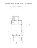
[0004] FIG. 1 is a simplified seal pattern illustrating a shape for the seal lines for the first liner illustrated in FIG. 4.
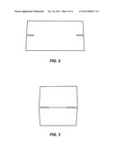
[0005] FIG. 2 illustrates a rigid or hard outer shell.
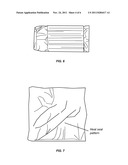
[0006] FIG. 3 illustrates the first liner inserted inside the hard outer shell.
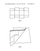
[0007] FIG. 4 illustrates the hard outer shell and the first liner in an opened format.
[0008] FIG. 5 illustrates the glue point between the first line and the hard outer shell.
[0009] FIG. 6 illustrates the first liner in a non-inflated state.
[0010] FIG. 7 illustrates examples of perimeter heat seals.
[0011] FIG. 8 illustrates a series of discontinuous heat seals to form the folding line.
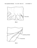
[0012] FIG. 9 illustrates the first liner (thermal liner) and the second liner (cushioning chamber) in a non-inflated state.
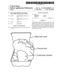
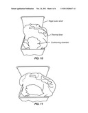
[0013] FIG. 10 illustrates the packaging structure after inflation.
[0014] FIG. 11 illustrates a thermal liner in a box formed after inflation.
DETAILED DESCRIPTION OF THE INVENTION
[0015] According to an embodiment of the present invention, a box is lined with multiple liners. A first liner that provides thermal insulation upon inflation can be an Airliner, available from the present assignee. The Airliner provides thermal protection for temperature sensitive and/or perishable products after inflation of the Airliner. The box could also be lined with a second liner that provides cushioning to absorb shocks.
[0016] According to embodiments of the present invention, a method is provided that is characterized by a process of forming one "rigid" thermal box via the inflation of the Airliner through a valve or entry point using, for example, a single step, eliminating one or more of the steps of forming the box, taping the bottom of the box, inserting the liner after inflation after folding the gussets, and the like. FIG. 1 illustrates the shape of the seal lines for the first liner illustrated in FIG. 4. Embodiments of the present invention are not limited to the particular shape and dimensions illustrated in FIG. 1.
[0017] A hard outer shell made of materials that provide mechanical rigidity is illustrated in FIG. 2. The hard outer shell can be made of corrugated paper such as e-flute, f-flute, or the like. The hard outer shell can be single or double wall as appropriate to the particular application. Although a paper-based hard outer shell is illustrated in FIG. 2, the hard outer shell can be corrugated or formed from a solid plastic. Embodiments of the present invention are not limited to the particular shell illustrated in FIG. 2.
[0018] FIG. 3 illustrates the first liner as it is inserted in the hard outer shell and fixing the position of the first liner. The position of the first liner is fixed by gluing, taping, or the like so that the shell and the first liner form a single unit.
[0019] FIG. 4 illustrates the hard outer shell and the first liner in an opened format. As illustrated in FIG. 4, the shape of the first liner is selected to provide a predetermined shape that may not cover all the portions of the hard outer shell. Embodiments of the present invention are not limited to the particular shape illustrated in FIG. 4. The first liner is pre-shaped by a series of heat seals for perimeter and folding lines to determine the final form after inflation. When the outer shell is folded together, the areas of the outer shell not provided with the first liner, overlap to provide for a single layer of the first liner inside the folded outer shell. The first inflatable liner for thermal insulation can be made using one or several films, including, but not limited to, LDPE, HDPE, Nylon, Surlyn, or the like.
[0020] As illustrated in FIG. 4, an embodiment of the present invention provides a hard outer shell with an inflatable liner attached to an interior portion of the hard outer shell. This embodiment can be provide for thermal insulation and some degree of mechanical cushioning for objects stored or shipped in the package. A valve is provided to inflate the first liner. In a particular embodiment, inflation of the first liner results in semi-automatic formation of the package as the air chambers in the liner inflate and take shape, providing pressure to construct the outer shell. One of ordinary skill in the art would recognize many variations, modifications, and alternatives. Thus, embodiments of the present invention include a cardboard box with an inflatable liner attached at one or more points inside the cardboard box. This combination box/liner can be provided to customers to enable economical packaging of objects benefiting from thermal insulation. Since the liner is assembled and shipped in a non-inflated condition, space savings are provided by embodiments of the present invention in comparison with other techniques.
[0021] FIG. 5 illustrates the glue point between the first line and the hard outer shell. The illustrated glue point is just an example and does not limit the present invention.
[0022] FIG. 6 illustrates the first liner in a non-inflated state. FIG. 7 illustrates examples of perimeter heat seals, which can be formed in a continuous or discontinuous manner. An example of discontinuous heat seals is illustrated in FIG. 8, where heat seals are formed to form the folding line.
[0023] In order to provide for both thermal insulation and mechanical insulation against shocks, dropping of the package, and the like, a second liner is provided to provide cushioning for the products stored in the package. FIG. 9 illustrates the first liner (thermal liner) and the second liner (cushioning chamber) in a non-inflated state. The second liner is typically attached to the first liner at one or more attachment points using tape, double-sided tape, glue, or the like.
[0024] FIG. 10 illustrates the packaging structure after inflation. Because of the integration of the multiple liners and the hard outer shell, inflation of the first inflatable liner and the second inflatable liner result in an action similar to an automatic formation of the packaging product. The folded lines align with the corner of the hard outer shell and the seal lines define the extent of the air chambers.
[0025] The liner for the cushioning chamber can be made using one or several films, including, but not limited to, LDPE, HDPE, Nylon, Surlyn, or the like. It is sealed or laminated to the first (thermal) liner. In order to provide for ease of assembly, both liners are inflated concurrently (e.g., at the same time) through a single valve or inflation entry point. Thus, a packaging product is provided that can be delivered as an integrated product, requiring only filling at a single valve to provide for both thermal and mechanical insulation.
[0026] Although embodiments of the present invention illustrated herein utilize both the first inflatable liner and the second inflatable liner inside the hard outer shell, other embodiments utilize only a single inflatable liner to provide thermal insulation for products stored or packaged in the packaging structure. FIG. 11 illustrates a thermal liner in a box formed after inflation. One of ordinary skill in the art would recognize many variations, modifications, and alternatives.
User Contributions:
Comment about this patent or add new information about this topic:
| People who visited this patent also read: | |
| Patent application number | Title |
|---|---|
| 20220281776 | METHOD FOR THE TREATMENT OF MAGNESIA-CARBON PRODUCTS |
| 20220281775 | COMPOSITE CERAMIC MEMBER AND METHOD FOR PREPARATION THEREOF, VAPORIZATION ASSEMBLY, AND ELECTRONIC CIGARETTE |
| 20220281774 | ULTRAFAST LASER WELDING OF CERAMICS |
| 20220281773 | METHOD OF MAKING CONCRETE |
| 20220281772 | Enhanced Adhesive Drywall Finish and Joint Compound and Method of Use |
Images included with this patent application:
 |  |
 |  |
 |  |
 |
| Similar patent applications: | |
| Date | Title |
|---|---|
| 2010-08-05 | Blister card packaging structure with a viewing panel |
| 2011-06-23 | Method for packing tab tape, and packing structure for tab tape |
| 2010-03-25 | Dunnage structure made with multiple ply partitions |
| 2010-03-25 | Water storage apparatus with structure of multiple layers |
| 2008-09-11 | Environmentally separable packaging device with attaching base |
| New patent applications in this class: | |
| Date | Title |
|---|---|
| 2022-05-05 | Inflation feature for package, inflation rig assembly, and method of inflating |
| 2016-05-19 | Inflatable packaging with apertures |
| 2016-05-19 | Inflatable packaging with adhesive seals |
| 2016-02-11 | Air bag packaging arrangement and self-adhesive checking valve |
| 2016-01-28 | Thermal insulation dunnage and method |
| New patent applications from these inventors: | |
| Date | Title |
|---|---|
| 2016-06-30 | Shipping product with thermal and mechanical insulation features |
| 2016-01-28 | Packaging product with thermal and mechanical insulation features |
| 2012-08-02 | Multi-layer metalized thermal bag |
| 2011-06-02 | Method and system for fillable gel pack |
| Top Inventors for class "Special receptacle or package" | |
| Rank | Inventor's name |
|---|---|
| 1 | Donald E. Weder |
| 2 | Brett R. Glass |
| 3 | Daniel Lee Bizzell |
| 4 | Andrea Biondi |
| 5 | Nicole E. Glass |