Patent application title: CYLINDER BLOCK ASSEMBLY FOR A HYDRAULIC DEVICE
Inventors:
Eric C. Bretey (Boone, IA, US)
Gregory H. Knop (Nevada, IA, US)
Assignees:
SAUER-DANFOSS INC.
IPC8 Class: AF01B3128FI
USPC Class:
921691
Class name: Expansible chamber devices cylinder detail
Publication date: 2011-11-24
Patent application number: 20110283881
Abstract:
A cylinder block assembly for a hydraulic device. The cylinder block
assembly includes a cylinder block with a plurality of piston bores
disposed therethrough. Circumferential grooves are disposed around the
piston bore such that an elastic bushing may be disposed within the
piston bore using a slip fit so that when the elastic material deforms
the material deforms into the circumferential groove. By deforming into
the circumferential groove the elastic bushing is locked in place and
axial movement of the bushing in the bore is prevented.Claims:
1. A cylinder block assembly for a hydraulic device comprising: a
cylinder block having at least one piston bore disposed therethrough; at
least one circumferential groove disposed around the piston bore; and an
elastic bushing disposed in the piston bore and within the
circumferential groove to prevent axial movement of the bushing in the
bore.
2. The cylinder block assembly of claim 1 wherein the elastic bushing is brass.
3. The cylinder block assembly of claim 1 wherein the circumferential grooves are greater than 10 microns in depth.
4. The cylinder block assembly of claim 1 wherein the circumferential grooves are less than 4000 microns in depth.
5. The cylinder block assembly of claim 1 wherein the elastic bushing has full circumferential contact with the cylinder block within the groove.
6. The cylinder block assembly of claim 1 wherein the elastic bushing deforms into the circumferential groove.
7. The cylinder block assembly of claim 1 wherein the bushing within the circumferential groove secures the bushing in the cylinder block.
8. The cylinder block assembly of claim 1 wherein the hydraulic device is an axial piston pump.
9. The cylinder block assembly of claim 1 wherein the elastic bushing is slip fit into the piston bore.
Description:
BACKGROUND OF THE INVENTION
[0001] This invention relates to a hydraulic assembly. More specifically, this invention relates to a cylinder block assembly for an axial piston hydraulic device.
[0002] In certain hydraulic axial piston pumps, a brass (or other material) bushing is inserted into the piston bore of a cylinder block. This is frequently done because the bushing material has tribiological or other properties that are superior to those of the cylinder block material.
[0003] The current method for retaining bushings in the piston bores of the cylinder block relies on forces resulting from interference and friction between the bushing and the bore into which the bushing is pressed to resist forces that would dislodge the bushing during operation. An expensive process that closely controls the surface textures and diameters of two parts is currently used to ensure the bushing remains in place during operation in the piston bore. Thus, a need in the art exists for a cylinder piston block that is both inexpensive, easy to control and facilitates the manufacturing process.
[0004] Thus, a principal object of the present invention is to provide a cylinder block assembly that is inexpensive to manufacture.
[0005] Another object of the present invention is to provide a cylinder block assembly that facilitates manufacturing without compromising performance or strength of the device.
[0006] These and other objects, features, and advantages will become apparent from the specification and claims.
BRIEF SUMMARY OF THE INVENTION
[0007] A cylinder block assembly for a hydraulic device. The cylinder block assembly includes a cylinder block that has at least one piston bore disposed therethrough. A circumferential groove is disposed around the piston bore such that an elastic bushing can be disposed within the bore. When disposed within the bore the elastic bushing deforms into the circumferential groove to prevent axial movement of the bushing within the bore.
BRIEF DESCRIPTION OF THE DRAWINGS
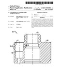
[0008] FIG. 1 is a sectional view of a cylinder block assembly;
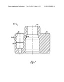
[0009] FIG. 2 is a sectional view of a cylinder block assembly including a bushing; and
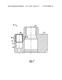
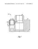
[0010] FIG. 3 is a sectional view of a cylinder block assembly with a deformed bushing therein.
DETAILED DESCRIPTION OF THE PREFERRED EMBODIMENT
[0011] The figures show a cylinder block assembly 10 for a hydraulic device such as an axial piston pump that utilizes an input shaft 12 to rotate a cylinder block 14 as is conventional in the art. The cylinder block 14 has a plurality of piston bores 16 disposed therethrough for receiving an axial piston (not shown).
[0012] A plurality of circumferential grooves 18 are disposed around each of the piston bores 16 on the inside diameter 17 of the bore 16. In a preferred embodiment the circumferential grooves are between 10 microns to 4000 microns in depth. Elastic bushings 20 are disposed within each of the piston bores 16 such that the outer diameter 21 of the elastic bushing 20 is disposed within the circumferential grooves 18 to prevent axial movement of the bushing 20 while in the piston bore 16. Specifically, the elastic bushing 20 once inserted into the bore 16 expands and deforms into the circumferential grooves 18 to provide full circumferential contact with the cylinder block 14 within the groove 18 so that the bushing 20 is locked and secured within the cylinder block 14 as shown in FIG. 3.
[0013] In operation, the bushing 20 is inserted into the piston bore 16 with a slip fit and plastically deforms thus expanding the outer diameter 21 of the bushing 20. This creates pressure between the outside diameter 21 of the bushing 20 and the inside diameter 17 of the bore 16. Thus, the circumferential grooves 18 allow the plastically deformed material of the bushing 20 to flow into the area created by the grooves 18. This locks the bushing 20 into place preventing the bushing 20 from being removed unless there is enough pull out force that causes shearing of the plastically deformed sections of the bushing. Thus, axial movement is prevented and the bushing 20 is secured within the cylinder block 14.
[0014] Thus provided is an improved cylinder block assembly 10 that requires only a slip fit between the outside diameter 21 of the bushing 20 and the inside diameter 17 of the bore 16 prior to the expansion operation. Tight tolerances on the two pieces to be joined is therefore not required thus lowering manufacturing and assembly costs.
[0015] In addition, specific surface textures conductive to high friction between the components do not need to be created using this new method as compared to prior art manufacturing methods. This eliminates certain manufacturing steps and lowers the cost of the assembly.
[0016] Additionally eliminated from the manufacturing process is the creation of a spiral groove on the outside diameter 21 of the bushing 20 to relieve hydraulic pressure or drain away fluid between the bushing 20 and cylinder block 14. Thus, this eliminates a machining step for the bushing 20 and again, lowers the cost of the assembly 10.
[0017] Another step that is eliminated from the manufacturing process due to the present cylinder block assembly 10 design is that the hydraulic press that is designed to overcome forces from assembling parts when an interference fit is presented is not required as in prior art methods. This eliminates a machine from the manufacturing process again, eliminating costs.
[0018] A final advantage provided is that there is no need to monitor and record the pressing force generated from overcoming the interference fit when inserting the bushing into the cylinder block bore. Again, costs are reduced yet performance and quality of the cylinder block assembly 10 is not compromised. Thus, at the very least all of the stated objectives have been met.
[0019] It will be appreciated by those skilled in the art that other various modifications could be made to the device without departing from the spirit and scope of this invention. All such modifications and changes fall within the scope of the claims and are intended to be covered thereby.
User Contributions:
Comment about this patent or add new information about this topic:
Images included with this patent application:
 |  |
 |  |
| Similar patent applications: | |
| Date | Title |
|---|---|
| 2011-12-29 | Pedal rod retaining assembly for a hydraulic brake system |
| 2011-12-15 | Piston-cylinder assembly having integrated measuring device |
| 2010-11-04 | Biaxial alignment assembly for force delivery device |
| 2009-08-13 | Bleeding system for a hydraulic steering system |
| 2010-12-16 | Cylinder block and method for the production of a cylinder block |
| New patent applications in this class: | |
| Date | Title |
|---|---|
| 2016-06-30 | Gasketless high pressure connection |
| 2016-06-02 | Linear compressor for a domestic appliance and domestic refrigeration appliance |
| 2016-04-07 | Cylinder head |
| 2016-03-24 | Multi-cylinder assembly |
| 2016-03-17 | Fluid pressure cylinder |
| Top Inventors for class "Expansible chamber devices" | |
| Rank | Inventor's name |
|---|---|
| 1 | Michael T. Lapp |
| 2 | Martin Bergmann |
| 3 | Rainer Scharp |
| 4 | Omar M. Kabir |
| 5 | Pawel A. Sobolewski |