Patent application title: Device and method for holding a personal electronic device
Inventors:
Thomas A. Nelson (Cedar Park, TX, US)
IPC8 Class: AB65D8500FI
USPC Class:
206525
Class name: Special receptacle or package with article content
Publication date: 2011-10-13
Patent application number: 20110247959
Abstract:
A device for holding a personal electronic device (PED), such as an
iPad®, using just one hand, in a relaxed and natural manner, allowing
the other hand to operate the PED. In one embodiment, a strap connects
diagonally opposed corner gripping elements, and the user inserts a hand
between the strap and the rear of the PED. In another embodiment, an
x-shaped strap connects four corner gripping elements. In another
embodiment, a swivel platen is mounted to a housing which connects two
two side gripping elements which hold the PED; and a hand retention strap
is provided on the platen so that the PED can be held and rotated in one
hand.Claims:
1. A holding device for a personal electronic device having a front
display, a rear surface, and a plurality of corners, the holding device
comprising a first corner gripping element secured to a first corner of
the portable electronic device; a second corner gripping element secured
to a second corner of the portable electronic device, the second corner
diagonally opposed to the first corner; and a glove connecting the first
corner gripping element and the second corner gripping element, such that
the glove is positioned on the rear side of the portable electronic
device.
2. The holding device of claim 1 wherein the glove is an elastic strap.
3. The holding device of claim 1 wherein the glove is a leather strap.
4. The holding device of claim 1 wherein the glove is an adjustable strap.
5. The holding device of claim 1 wherein the first corner gripping element is looped around the first corner of the portable electronic device.
6. The holding device of claim 1 wherein the first corner gripping element is looped around or attached to a first corner of case which contains the portable electronic device.
7. The holding device of claim 1 further comprising a first rivet connecting the first corner gripping element to the glove; and a second rivet connecting the second corner gripping element to the glove.
8. The holding device of claim 1 further comprising a third corner gripping element secured to a third corner of the portable electronic device and connected to the glove; and a fourth corner gripping element secured to a fourth corner of the portable electronic device and connected to the glove.
9. The holding device of claim 8 further comprising a finger access hole.
10. The holding device of claim 8 wherein the third corner gripping element further comprises a personal electronic device control access hole.
11. A method for holding and operating a personal electronic device having a front display, a rear surface, and a plurality of corners, the method comprising providing a holding device comprising a plurality of corner gripping elements, and a glove attached to each of the corner gripping elements; attaching the corner gripping elements of the holding device to the personal electronic device; inserting a first hand between the glove and the personal electronic device; and operating the personal electronic device with a second hand.
12. A holding device for a personal electronic device having a front display, a rear surface, a first side, and a second side opposite of the first side, the holding device comprising a first side gripping element secured to the first side of the portable electronic device; a second side gripping element secured to the second side of the portable electronic device; a housing in proximity to the rear surface of the personal electronic device, the housing connecting the first side gripping element and the second side gripping element; and a swivel platen mounted to the housing, the swivel platen comprising a hand retention element.
13. The holding device of claim 12 wherein the hand retention element is a strap.
14. The holding device of claim 13 wherein the strap is an elastic material
15. The holding device of claim 12 wherein the swivel platen further comprises a palm rest.
16. The holding device of claim 12 wherein the swivel platen further comprises a tactile finger grip.
Description:
RELATED APPLICATIONS
[0001] This application is related to U.S. Provisional Application No. 61/322,279 filed Apr. 8, 2010 by applicant, and claims the priority date of that application.
BACKGROUND
[0002] 1. Field of the Invention
[0003] This invention relates to maintaining positive tactile control over a personal electronic device (PED) using just one hand, in a relaxed and natural manner, allowing the other hand to operate the PED.
[0004] 2. Prior Art
[0005] One embodiment of the current invention is a strap or glove for holding portable electronic devices with one hand in a relaxed fashion. The current generation of portable electronic devices (PED) are difficult to hold with one hand, requiring the user to grasp the device from the edge and maintain a firm grip while holding it. Grasping the portable electronic device from the edge quickly becomes fatiguing.
SUMMARY OF THE INVENTION
[0006] The use of a strap, band or glove allows the PED to be held securely with one hand, relaxed, not gripping, while the other hand can operate the device. This is especially practical when demonstrating something on the device to one or more people in a group setting.
[0007] In one embodiment, a single strap or "glove" running diagonally across the back of the PED allows the PED to be held comfortably. This is referred to as the I-Band, due to the shape of the hand retention glove being that of an "I". The hand retention strap can be made of an elastic material to accommodate different size PEDs or hands. Corner mounting straps can be made of stretchable material, again, to accommodate different sized PEDs. If the corner mounting strap and hand retention glove are both made of relatively non-stretchable materials, the hand retention glove may be made of an adjustable strap, such as with hook and loop fasteners, or an adjustable strap, via a looping mechanism.
[0008] The use of a strap, band or glove allows the PED to be held securely with one hand, relaxed, not gripping, while the other hand can operate the device. This is especially practical when demonstrating something on the device to one or more people in a group setting.
[0009] In another embodiment, one strap or "glove" can be attached to all four corners of the PED. This is referred to as the X-Band, due to the shape of the hand retention glove being that of an "X". The hand retention glove may be made of an elastic material to accommodate different hand sizes and PED sizes.
[0010] In another embodiment, the strap, band or glove is mounted on a rotating platen to allow any angle viewing without removing the hand from the device. This platen may be flush with the device or wedge shaped, which allows a more comfortable angle of the wrist while using the PED for reading of viewing movies.
[0011] The platen can have attachments to allow the PED to be placed on a horizontal surface or mounted on a vertical surface. This would allow the PED to be used entirely hands free at a more comfortable viewing angle.
BRIEF DESCRIPTION OF THE DRAWINGS
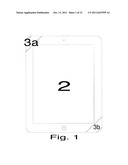
[0012] FIG. 1 is a front view of a rectangular personal electronic device with a first embodiment holding device attached to two opposite corners of the portable electronic device.
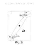
[0013] FIG. 2 is a rear view of the rectangular personal electronic device and the first embodiment holding device of FIG. 1.
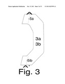
[0014] FIG. 3 is a detailed front view of a first corner gripping element 3a of the first embodiment holding device of FIG. 1 which shows rivet holes.
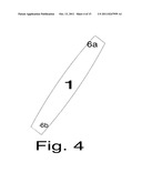
[0015] FIG. 4 is a detailed front view of the strap 1 of the first embodiment holding device of FIG. 1 which shows rivet holes for aligning and attaching the corner gripping elements.
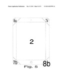
[0016] FIG. 5 is a front view of a rectangular personal electronic device and the second embodiment holding device attached to four corners of the personal electronic device
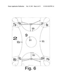
[0017] FIG. 6 is a rear view of the rectangular personal electronic device and the second embodiment holding device of FIG. 5.
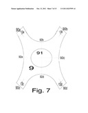
[0018] FIG. 7 is a detailed view of the strap 9 of the second embodiment holding device of FIG. 5. It shows rivet holes for aligning and attaching the corner gripping elements.
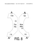
[0019] FIG. 8 is a detail of the corner gripping elements of the second embodiment holding device of FIG. 5.
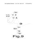
[0020] FIG. 9 is a detail of one method of assembly by securing the corner mounting straps to the hand retention glove of second embodiment of this invention.
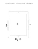
[0021] FIG. 10 is a front view of a rectangular personal electronic device and the third embodiment holding device grasping the device from the side.
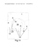
[0022] FIG. 11 is a rear view of the third embodiment holding device and the PED.
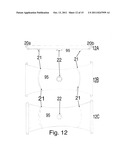
[0023] FIG. 12 is a detail of the main frame of the third embodiment holding device which grasps the PED.
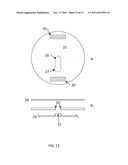
[0024] FIG. 13 is a detail view of one implementation of the swivel platen mounting mechanism.
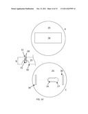
[0025] FIG. 14 is a detail view of one implementation of the hand retention strap mounting mechanism.
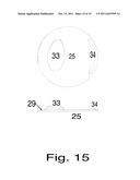
[0026] FIG. 15 is a detail of the ergonomic features of the third embodiment holding mechanism.
DETAILED DESCRIPTION OF EMBODIMENT
"I-Band" Two Corner Holding Device
[0027] FIG. 1 is a front view of a rectangular personal electronic device ("PED") 2 with a first embodiment holding device attached with a first corner gripping element 3a and a second corner gripping element 3b to two opposite corners of the portable electronic device.
[0028] FIG. 2 is a rear view of the rectangular personal electronic device and the first embodiment holding device 100 of FIG. 1. A strap 1 is positioned on the rear portion of the portable electronic device, and connects the first corner gripping element 3a to the second corner gripping element 3b. In this specification, the strap or combination of straps attached to the corner gripping elements is called a "glove".
Corner Gripping Elements
[0029] The combination of the corner gripping elements and the strap provides a secure attachment of the holding device to the PED. The I-band 100 is designed to provide sufficient tension to maintain the corner gripping elements 3 securely in place and to secure the PED 2 to the users holding hand when the holding hand is inserted between the I-band 1 and the PED 2.
[0030] In the example shown the corner gripping elements are inelastic straps, such as leather, which are riveted together with a first rivet 4a and a second rivet 4b. Each rivet passes through rivet holes 5a and 5b in the corner gripping element, FIG. 3, and through either the upper 6a or lower 6b rivet hole in the I-Band 1 of FIG. 4. The rivet is one of many connection techniques. In other examples, the corner gripping elements are each snapped together around a PED corner.
[0031] In other examples, the corner gripping elements are elastic straps which are sewn onto the strap 1. In other examples, the corner gripping elements comprise hook and loop fastening elements so that the corner gripping element may be wrapped around a corner and secured to itself or secured to the strap 1.
[0032] FIG. 3 is a detailed front view of a first corner gripping element 3a of the first embodiment holding device of FIG. 1 which shows rivet holes 5a and 5b. FIG. 3 shows the corner gripping element as a grasping strap 3 which is to be wrapped around a corner of the PED. In this example, the first and second corner gripping elements are of identical design, though they do not need to be. Rivet holes 5a and 5b are used for rivets to attach the grasping straps to the I-band. The grasping strap is formed by joining the top to the bottom to form a loop. When this is done properly, surface A on the top of FIG. 3 is aligned directly on top of the respective surface A' at the bottom of FIG. 3. Proper alignment is achieved when rivet alignment holes 5a and 5b are aligned as well as surface A.
[0033] In the example shown, the corner gripping elements are attached directly to the corners of the PED. In other examples, a carrying case is provided for the PED, and the corner gripping elements are attached to the case.
Glove and Glove Adjustment
[0034] FIG. 4 shows the I-band strap 1. The I-band strap 1 is used to maintain tension on the corner gripping elements to provide a secure attachment to the PED 2. The I-band strap also maintains sufficient pressure to provide a secure grip to the PED 2 when the holding hand is inserted between the I-band strap 1 and PED 2. In one example, rivet alignment holes 6a and 6b are used for assembly of the strap to the corner gripping elements to ensure correct alignment. The specific length and width of the I-band is dependent on the choice of material, PED 2 being targeted, and snugness of the fit after attaching the invention to the PED 2.
[0035] In one example, the strap is an elastic band which stretches to accommodate different sizes of personal electronic devices, or to permit a user's hand to be placed between the strap and the rear of the portable electronic device.
[0036] The glove adjustment allows the strap, band or glove to accommodate any size hand and PED's of different geometry.
Methods of Assembly and Use
[0037] In this embodiment, the corner mounting straps are prepared by wrapping edge A on top of edge A' in FIG. 3. This will align rivet holes 5a and 5b on top of each other. Rivet 4a is inserted through rivet holes 5a, 5b and 6a, I-Band 1 FIG. 4, to form the attachment. The second corner mounting strap is attached to the I-Band 1 through rivet hole 6b using rivet 4b.
[0038] The two corner mounting straps 3a, 3b, two rivets 4a, 4b and I-Band 1, when assembled, form the I-Band 100. The I-Band, the first embodiment of this invention, is attached to the PED by securing the corner mounting straps 3a, 3b to diagonal corners of the PED, as shown in FIG. 1. By securing the corner mounting straps as described, the I-Band 1 is stretched. This stretching provides tension, keeping the corner mounting straps 3a, 3b held securely in place as well as providing a snug fit when the hand is inserted between the I-Band 1 and the PED 2.
DETAILED DESCRIPTION OF EMBODIMENT
"X-Band" Four Corner Holding Device
[0039] This embodiment of the invention is shown in FIGS. 5-9.
[0040] FIG. 6 shows the rear view of a second embodiment holding device 120 attached to a PED 2. In this example, the holding device includes four corner gripping elements 7a, 7b, 8a, and 8b which are connected by an x-shaped glove 9. In another example, a holding device includes three corner gripping elements.
[0041] In FIG. 6, the four corner gripping elements 7a, 7b, 8a, and 8b are wrapped around the corners of the PED 2. A hand retention glove 9 is attached to the four corner gripping elements via rivets 10. In one example, the hand retention glove 9 is sized to require enough stretching so the holding hand, when inserted between the PED 2 and hand retention glove 9, provides a secure feel.
[0042] FIG. 5 shows the front of a rectangular PED 2 and four corner gripping elements 7a, 7b, 8a, and 8b which secure the PED 2 to a glove (not shown.
[0043] FIG. 7 shows the hand retention glove 9 in the example of FIG. 6. The four corners of the glove 90a, 90b, 90c, and 90d each have a rivet guide hole 13 punched through for attaching a rivet. In other examples, other attachment methods may be used to secure the glove to the corner gripping elements.
[0044] In the example of FIG. 7, The center of the glove has a large finger access hole 91 to allow finger access. This will allow the hand retention glove 9 to be worn in multiple configurations, with fingers exiting the hole or fingers entering the hole. In another example, the user inserts a hand behind the glove, and the finger access hole provides relief for rings on the user's fingers.
[0045] FIG. 8 is a detailed front view of a first corner gripping element 7a which shows rivet holes 12a and 12b; and the fourth corner gripping element 8b which shows rivet holes 12g and 12h. Similar first corner gripping element straps 7b and 8a are provided so that corner gripping element straps 7a and 7b, and 8a and 8b are used in pairs at opposite corners.
[0046] Rivet holes 12a-h are pre-punched in the corner gripping element straps to allow for ease of manufacturing and to ensure a consistent product. In this example, the grasping straps 7a, 7b, 8a, and 8b are each wrapped to form a corner loop. Surfaces A and A' and rivet holes 12 are aligned to form the loop. PED control access holes 11 are punched out to allow access to the PED 2 controls. These holes 11 are punched according to the PED's 2 specific control locations. Because PED's are rectangular, not square, the holding device 120 can only be oriented in two directions, it will not fit if attempted to mount sideways. The access holes 11 will align to the PED 2 controls if mounted upside up. If mounted upside down, the PED 11 controls will not be accessible.
[0047] FIG. 9 shows the attachment of corner gripping element 7a to the hand retention glove 9. The grasping straps rivet alignment holes 12a and 12b and hand retention glove alignment hole 13a are all aligned. A rivet 10 is inserted through the three alignment holes. A stress retaining washer 14 is applied to the opposite side of the hand retention glove 9 from the corner gripping element 7a. A rivet 10 completes the attachment of the grasping straps 7a to the hand retention glove 9. In this example, the other corner gripping elements 7b, 8a, and 8b are attached to the glove in a similar manner.
[0048] FIG. 9 illustrates one method of attaching the pieces. Any suitable method that is well engineered will suffice. Alternate attachment methods include using stitching provided by a sewing machine to sew the corner mounting strap 7a-8b to itself, aligning edges A and A', then sewing the corner mounting straps to the hand retention glove 9 corners 90a-d. Yet another method would be to use industrial staples for attachment. After aligning the corner mounting strap 7a-8b onto itself, place the pre-aligned unit over the corner 90a-d of the hand retentions glove 9, then staple the entire unit together with one or more staples. A third alternate method would be to use industrial strength adhesive to glue the pieces of the second embodiment 120 together after pre aligning as described previously.
Methods of Assembly and Use
[0049] In this embodiment the corner mounting straps are made by wrapping edge A on top of edge A', FIG. 9. This will align rivet holes 12a and 12b on top of each other. Rivet 10a is inserted through rivet holes 12a, 12b and 13a, X-Band 9, and stress retaining washer 14 to form the attachment. The three remaining corner mounting straps are attached to the X-Band 9 through rivet hole 13b-d using rivets 10b-d.
[0050] The four corner mounting straps 7a-8b, rivets 10a-d, stress retaining washers 14 and X-Band 9, when assembled, form the second embodiment of the invention, the X-Band 120. The X-Band 120 is attached to the PED 2 by securing the four corner mounting straps 7a-8b to the corners of the PED 2, as shown in FIG. 5. By securing the corner mounting straps as described, the hand retention glove 9 is stretched. This stretching provides tension, keeping the corner mounting straps 7a-8b held securely in place as well as providing a snug fit when the hand is inserted between the hand retention glove 9 and the PED 2.
[0051] The hand can be inserted between the hand retention glove 9 and the PED 2 through any of the perimeter access locations 92a-d. The center hole 21 in the hand retention glove 9 provides more flexibility in how the PED 2 is held. The center hole 91 allows several fingers to be inserted through the hole 91 to provide a secure grip. Because of the shape, circular, the orientation is not limited to any of the four axis's provided by the perimeter access locations 92a-d. The PED 2 can be held in any of a full 360 degree rotation.
[0052] The strap, band or glove may have various configurations to allow multiple ways to hold the PED comfortably. This will include plain straps, straps with different shapes such as an "X" shape and "Y" shape, straps with holes, pouches, pockets and gloves.
DETAILED DESCRIPTION OF EMBODIMENT
Swivel Grip
[0053] This embodiment of the invention is shown in FIGS. 10-15.
[0054] FIG. 11 shows the rear view of a holding device 140 attached to a PED 2. In this example, the holding device 140 includes two side gripping elements 20a and 20b, and a swivel platen 25 mounted to the side gripping elements 20a and 20b in such a manner as to allow the swivel platen to rotate a full 360 degrees.
[0055] In this example, the two side gripping elements 20a and 20b are part of a single housing 92 which traverses the width of the PED 2, wraps around portions of opposing edges of the PED 2 and clasp the front of the PED 2.
[0056] Swivel platen guide brackets 21 maintain the rigidity of the swivel platen 25 and prevent misalignment. Hand retention strap 28 is a stretchable material used to secure the holding hand to holding device. Ergonomic palm rest 33 provides a comfortable mound to rest the palm of the holding hand. Finger grip 34 provides a tactile grip for the holding hand for a more assured grip while holding.
[0057] FIG. 10 shows the front of the PED 2 and the side gripping elements 20a and 20b. The grasping mechanism 140 is secured to the PED by pressure and contact area. As such, it can be moved up and down the PED 2 simply by sliding it, no mechanical attachment is loosened.
[0058] FIGS. 12A, 12B, and 12C shows several views of the grasping mechanism.
[0059] FIG. 12A shows a cross section of the housing 95, side gripping elements 20a and 20b, the swivel platen guide brackets 21 and a swivel platen mounting bolt 22.
[0060] FIG. 12B shows the underside of the housing 95 and grasping mechanism 20a, 20b. The swivel platen mounting bolt 22 allows the platen 25 to rotate freely a full 360 degrees. The swivel platen guide brackets 21 prevent the swivel platen 25 from losing grasp on the retaining bolt 22
[0061] FIG. 12C shows the top of the housing 95 and grasping mechanism 20a, 20b. The top of the housing 95 is smooth and contoured to fit the back of the PED 2, which it will be in contact with.
[0062] FIGS. 13A and 13B shows the swivel platen 25 details.
[0063] FIG. 13A is a top view showing the mounting key 26 and mounting bolt insertion hole 27.
[0064] FIG. 13B is a cross section view of the swivel platen 25 showing how the mounting bolt 22 fits into the mounting key 26. Also shown is the hand comfort pad 29, which may be simply a layer of felt, cloth, rubber or other suitable material to provide a more comfortable surface for the holding hand.
[0065] FIG. 14A is a top view of the swivel platen 25 showing the hand retention strap 28.
[0066] FIG. 14C is the bottom view of the swivel platen 25. The retaining pin cavity 30 is shown near the diameter of the swivel platen 25 along the horizontal diameter. The mounting key 26 runs toward the retaining pin cavity, ending in the mounting key access hole 27.
[0067] FIG. 14B is a cross section of the retaining pin cavity. This shows one implementation of mounting the hand retention strap 28. In this embodiment, the hand retention strap 28 enters the cavity 30 from the top, loops around the retention pin 31 back onto itself. The hand retention strap 28 is secured by stitching or stapling to itself. The retention pin 31 is large enough to prevent the strap 28 being pulled through the top of the swivel platen 25 through the narrow port of the retention cavity 32.
[0068] FIG. 15 shows the ergonomic amenities of the swivel platen. The hand retention strap 28, retaining pin cavity 30 and mounting key access hole 27 are not draw to allow clarity of the displayed features.
[0069] FIG. 15A shows the top view of the ergonomic palm rest 33 and finger grip 34.
[0070] FIG. 15B shows a side view of the ergonomic palm rest 33 and finger grip 34. The ergonomic palm rest 33 and finger grip 34 are both mounted on the swivel platen 25 on top of the hand comfort pad 29. These two features will be made of soft, gelatinous material to allow maximum comfort while using the embodiment.
[0071] In another example, the rotating platen has attachments that allow the PED to stand at various angles to permit movie viewing or book reading when placed on a surface.
[0072] In another example, the rotating platen has attachments that allow the PED to be affixed to a wall or other surface, thereby allowing the PED to be viewed in any orientation through the 360 degree rotation.
[0073] The current invention is not limited to the specific embodiments and examples described above, and variations will be apparent to those skilled in the art.
User Contributions:
Comment about this patent or add new information about this topic:
Images included with this patent application:
 |  |
 |  |
 |  |
 |  |
 |  |
 |  |
 |  |
 |
| Similar patent applications: | |
| Date | Title |
|---|---|
| 2011-10-27 | Devices and method for handling microelectronics assemblies |
| 2011-09-29 | Cases and covers for handheld electronic devices |
| 2009-06-18 | Golf bag having shoulder strap with an electronic device |
| 2011-10-13 | Pressure-relief valve of a housing for an electrical/electronic unit |
| 2011-10-27 | Apparatus for holding portable electronic device |
| New patent applications in this class: | |
| Date | Title |
|---|---|
| 2016-06-23 | Squeeze and turn child resistant closure attachment |
| 2016-03-17 | Process to transfer wine in bottles to box-form retail package |
| 2016-02-11 | Packaging device for a cosmetic product, in particular for a degassing cosmetic product |
| 2016-01-21 | Flexible water-soluble articles |
| 2016-01-14 | Hose storage apparatus |
| Top Inventors for class "Special receptacle or package" | |
| Rank | Inventor's name |
|---|---|
| 1 | Donald E. Weder |
| 2 | Brett R. Glass |
| 3 | Daniel Lee Bizzell |
| 4 | Andrea Biondi |
| 5 | Nicole E. Glass |