Patent application title: MOBILE TERMINAL
Inventors:
Chin-Hu Chen (Tu-Cheng, TW)
Chun-Chung Lai (Tu-Cheng, TW)
Jui-Hsiang Lin (Tu-Cheng, TW)
Assignees:
HON HAI PRECISION INDUSTRY CO., LTD.
IPC8 Class: AA47B8100FI
USPC Class:
3123191
Class name: Supports: cabinet structure with movable components having biasing means
Publication date: 2011-09-29
Patent application number: 20110234069
Abstract:
A mobile terminal includes a base body, a pair of slidable bodies and a
pair of switch mechanisms disposed on the slidable bodies. Each of the
switch mechanism includes a housing, a cover, an operating member, a
locking member and a spring unit. The operating member includes a
coupling portion received in the housing and an operating cap located out
of the housing. The coupling portion includes a base bevel. The locking
member received in the housing includes a sliding bevel contacting to the
base bevel and a locking block passing through the cover and engaging
with the base body. The spring unit urges between the locking member and
the housing. When the operating cap is pressed towards the housing, the
base bevel engages with the sliding bevel to drive the locking member
compress the spring unit, thereby the locking block disengaging from the
base body.Claims:
1. A mobile terminal, comprising a base body; a pair of slidable bodies,
slidably mounted to the base body; and a pair of switch mechanisms,
disposed on the pair of slidable bodies to lock the pair of slidable
bodies to the base body respectively, each of the switch mechanisms
comprising: a housing, defining an opening towards the base body; a
cover, fixed to the housing and covering the opening, the cover defining
a through hole; an operating member, comprising a coupling portion and an
operating cap, the coupling portion received in the housing and
comprising a base bevel, the operating cap extending outwardly from the
housing; a locking member, received in the housing and comprising a
sliding bevel opposite to and collaborating with the base bevel and a
locking block passing through the through hole in the cover to engage
with the base body to position the corresponding slidable body to the
base body; and a spring unit, urged between the locking member and the
housing; wherein when the operating cap is pressed towards the housing,
the base bevel of the operating member engages with the sliding bevel to
drive the locking member compress the spring unit, thereby the locking
block disengaging from the base body.
2. The mobile terminal as claimed in claim 1, wherein the base body defines a pair of base positioning slots located close to a middle part of the base body, and the locking members engage with the pair of base positioning slots to position the slidable bodies at a closed position.
3. The mobile terminal as claimed in claim 2, wherein the base body defines a pair of slidable positioning slots located two opposite ends of the base body respectively, and the locking members engage with the pair of slidable positioning slots to position the slidable bodies at an open position.
4. The mobile terminal as claimed in claim 3, wherein the base body defines two pairs of slidable grooves extending from the middle part towards two opposite ends of the base body respectively, accordingly, each of the slidable body comprises a pair of slidable blocks slidably received in the corresponding pair of the slidable grooves.
5. The mobile terminal as claimed in claim 4, wherein the base body comprises two pairs of fixing blocks fixed in the two pairs of slidable grooves to prevent the pair of slidable bodies separate from the base body.
6. The mobile terminal as claimed in claim 5, wherein the cover of the switch mechanism comprises a pair of hooks, the housing defines a pair of locking grooves, and the cover is fixed to the housing via the hooks engaging with the locking grooves.
7. The mobile terminal as claimed in claim 6, further comprising two pairs of cushions surrounding the two pairs of slidable blocks respectively, and located between the two pairs of slidable grooves and the two pairs of slidable blocks to protect the slidable blocks from abrasion.
Description:
BACKGROUND
[0001] 1. Technical Field
[0002] The present disclosure generally relates to mobile terminals, and more particularly to slidable bodies of mobile terminals.
[0003] 2. Description of Related Art
[0004] Generally, a mobile terminal includes a pair of slidable bodies to reduce the size of the mobile terminal at a closed position. The slidable bodies are connected to a body of the mobile terminal by slide mechanisms. Therefore, how to make the slide mechanisms to be simple structures and gain a small size of the mobile terminal is a problem in study.
[0005] Therefore, a need exists in the industry to overcome the described problem.
BRIEF DESCRIPTION OF THE DRAWINGS
[0006] Many aspects of the present embodiments can be better understood with reference to the following drawings. The components in the drawings are not necessarily drawn to scale, the emphasis instead being placed upon clearly illustrating the principles of the present embodiments. Moreover, in the drawings, all the views are schematic, and like reference numerals designate corresponding parts throughout the several views.
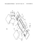
[0007] FIG. 1 is an exploded view of a mobile terminal of an exemplary embodiment of the disclosure.
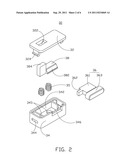
[0008] FIG. 2 is an exploded view of a switch mechanism of the mobile terminal of FIG. 1.
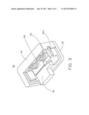
[0009] FIG. 3 is an assembled perspective view of FIG. 2.
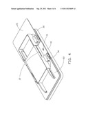
[0010] FIG. 4 is an assembled perspective view of the mobile terminal of FIG. 1 with one slidable body in an open position.
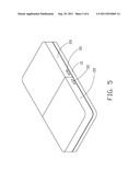
[0011] FIG. 5 is an assembled perspective view of the mobile terminal of FIG. 1 in a closed position.
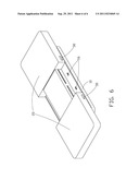
[0012] FIG. 6 is an assembled perspective view of the mobile terminal of FIG. 1 with two slidable bodies in the open position.
DETAILED DESCRIPTION
[0013] The disclosure is illustrated by way of example and not by way of limitation in the figures of the accompanying drawings in which like references indicate similar elements. It should be noted that references to "an" or "one" embodiment in this disclosure are not necessarily to the same embodiment, and such references mean at least one.
[0014] Referring to FIG. 1, a mobile terminal 100 comprises a base body 10, a pair of slidable bodies 20 and a pair of switch mechanisms 30. In an exemplary embodiment, the mobile terminal 100 may be but not limited to a mobile phone, a personal digital assistant (PDA), a digital information appliance, for example. The pair of slidable bodies 20 are slidably mounted to the base body 10. The pair of switch mechanisms 30 are disposed on the pair of slidable bodies 20 respectively and used to lock the pair of slidable bodies 20 to the base body 10 in an open position and a closed position.
[0015] The base body 10 defines two pairs of slidable grooves 12 and the base body 10 comprises two pairs of fixing blocks 14. The two pairs of slidable grooves 12 are located on two sidewalls 11 of the base body 10 and extend from a middle part towards two opposite ends of the base body 10 respectively. Each of the slidable grooves 12 defines an opening end 121, where one corresponding of the fixing blocks 14 is fixed.
[0016] The base body 10 further defines a pair of base positioning slots 16 located close to the middle part of the base body 10 and a pair of slidable positioning slots 18 located close to the two opposite ends of the base body 10 respectively.
[0017] The pair of slidable bodies 20 slide related to the base body 10 towards two opposite directions. Each of the slidable bodies comprises a base 22 and an enclosure 24. Each of the enclosures 24 mounted to the base 22 defines a receiving hole 246. Each of the base 22 comprises a pair of slidable blocks 222 received in the corresponding pair of the slidable grooves 12 to slidably mount the corresponding slidable body 20 to the base body 10. The fixing blocks 14 are fixed in the opening ends 121 of the two pairs of slidable grooves 12 to prevent the pair of slidable bodies 20 separate from the base body 10.
[0018] In this embodiment, the base 22 defines a receiving room 221. The two pairs of slidable blocks 222 are protruding from the base 22 towards into the receiving room 221. The two sidewalls 11 of the base body 10 are received in the receiving room 221.
[0019] Referring to FIG. 2 and FIG. 3, each of the pair of switch mechanisms comprises a housing 34, a cover 32, an operating member 36, a locking member 38 and a spring unit 35. The housing defines an opening 342 towards the base body 10, a pair of locking grooves 344 and a passing groove 346. The cover 32 is fixed to the housing 34 and covers the opening 342. The cover 32 defines a through hole 322 and comprises a pair of hooks 324 engageable with the locking grooves 344 to fix the cover 32 to the housing 34. The operating member 36 passes through the passing groove 346, and comprises a coupling portion 361 received in the housing 34 and an operating cap 363 extending outwardly from the housing 34 through the passing groove 346. The coupling portion 361 comprises a base bevel 362. That is, the base bevel 362 and the operating cap 363 are respectively defined at two opposite edges of the operating member 36. The operating cap 363 is on outer surface of the mobile terminal 100 and can be used as an operating instrument for a user. That is, the operating cap 363 can be designed as a switch of the mobile terminal 100 and be pressed by a user to drive the base bevel 362 to move.
[0020] The locking member 38 is received in the housing 34 and comprises a sliding bevel 382 opposite to and collaborating with the base bevel 362, and a locking block 384 passing through the through hole 322 in the cover 32 to engage with the base body 10 so as to position the corresponding slidable body 20 to the base body 10. When the locking blocks 384 are engaged with the base positioning slots 16, the slidable bodies 20 are positioned at a closed position. When the locking blocks 384 are engaged with the slidable positioning slots 18, the slidable bodies 20 are positioned at an open position.
[0021] The spring unit 35 urges between the locking member 38 and the housing 34. In this embodiment, the spring unit 35 comprises a pair of compression springs. The housing 34 defines a pair of recesses 345 to locate the pair of compression springs respectively. One ends of the compression springs are positioned in the recesses 345, and the other ends of the compression springs urge against the locking member 38.
[0022] When the operating member 36 is pressed towards the housing 34, the base bevel 362 of the operating member 36 engages with the sliding bevel 382 to drive the locking member 38 move perpendicularly to the operating member 36 as well as compress the spring unit 35, thereby the locking block 384 disengaging from the base body 10 and the corresponding slidable body 20 can slide related to the base body 10.
[0023] The switch mechanisms 30 are secured between the bases 22 and the enclosures 24 of the slidable bodies 20. The operating caps 363 of the operating members 36 pass through the receiving holes 246 of enclosures 24 for user's operation.
[0024] In this embodiment, the mobile terminal 100 further comprises two pairs of cushions 40 surrounding the two pairs of slidable blocks 222 respectively, and located between the slidable grooves 12 and the slidable blocks 222 to protect the slidable blocks 222 from abrasion.
[0025] Referring to FIG. 4, an assembled perspective view of the mobile terminal in open position is shown. In this position, one of the slidable bodies 20 is at the closed position, and the other is at the open position.
[0026] Referring to FIG. 5, the pair of slidable bodies 20 attach to each other at the closed position. In this position, the locking blocks 384 are received in the base positioning slots 16, and the mobile terminal 100 has a small size. In use, the user presses the operating caps 363 of the operation members 36 to make the slidable bodies 20 disengage from the base body 10, and slides the slidable bodies 20 towards two opposite ends of the base body 10. When the slidable bodies 20 arrive the two opposite ends of the base body 10 respectively, the locking blocks 384 meet the slidable positioning slots 18, and the locking blocks 384 move into the slidable positioning slots 18 under elasticity of the spring unit 35, so that the pair of slidable bodies 20 are fixed at the open position, as shown in FIG. 6.
[0027] In the embodiment, the slidable bodies 20 slide related to the base body 10 via engagement between the slidable blocks 222 and the slidable grooves 12 without any other slidable mechanisms. Therefore, the mobile terminal 100 has a simple structure.
[0028] Although the features and elements of the present disclosure are described as embodiments in particular combinations, each feature or element can be used alone or in other various combinations within the principles of the present disclosure to the full extent indicated by the broad general meaning of the terms in which the appended claims are expressed.
User Contributions:
Comment about this patent or add new information about this topic:
| People who visited this patent also read: | |
| Patent application number | Title |
|---|---|
| 20140029771 | MULTIPLE INPUT AUDIO SWITCH |
| 20140029770 | HYBRID ANALOG/DIGITAL HEADSET |
| 20140029769 | REFERENCE VOLTAGE GENERATION CIRCUIT |
| 20140029768 | DATA COMMUNICATION USING AUDIO PATTERNS SYSTEMS AND METHODS |
| 20140029767 | Downmixing Control |
Images included with this patent application:
 |  |
 |  |
 |  |
| Similar patent applications: | |
| Date | Title |
|---|---|
| 2008-12-11 | Mobile high bay storage system having vehicle guidance system |
| 2010-04-22 | Mobile operating table and storage device |
| New patent applications in this class: | |
| Date | Title |
|---|---|
| 2016-07-14 | Laundry treatment apparatus comprising a receiving device |
| 2016-06-09 | Cover assembly |
| 2016-06-02 | Self-closing slide rail assembly with deceleration mechanism |
| 2016-03-31 | A damping or return device for sliding door leaves |
| 2016-01-14 | Lift handles having safety interlocks for a rack-mounted enclosure |
| New patent applications from these inventors: | |
| Date | Title |
|---|---|
| 2013-06-20 | Illuminating module for portable electronic device |
| 2013-03-28 | Peripheral device for portable electronic device |
| 2011-02-03 | Portable electronic device |
| 2010-12-02 | Hinge and electronic device employing the same |
| 2010-11-18 | Battery cover structure for portable electronic device |
| Top Inventors for class "Supports: cabinet structure" | |
| Rank | Inventor's name |
|---|---|
| 1 | Yun-Lung Chen |
| 2 | Karl-Friedrich Laible |
| 3 | Jae Hoon Lim |
| 4 | Chen-Lu Fan |
| 5 | Wen-Tang Peng |