Patent application title: ACTIVE TIP CLEARANCE CONTROL FOR SHROUDED GAS TURBINE BLADES AND RELATED METHOD
Inventors:
Harold Edward Miller (Glenville, NY, US)
Assignees:
GENERAL ELECTRIC COMPANY
IPC8 Class: AF01D1122FI
USPC Class:
415 1
Class name: Rotary kinetic fluid motors or pumps method of operation
Publication date: 2011-09-22
Patent application number: 20110229301
Abstract:
A turbine bucket tip clearance control system includes a rotor assembly
having a rotor supporting a plurality of axially spaced wheels, each
wheel mounting an annular row of buckets, the annular row of buckets on
at least one of the plurality of axially-spaced wheels having a radially
outer tip shroud provided with at least one seal tooth. A stator assembly
includes a radially inwardly facing, axially-stepped surface, formed with
radially inner and outer seal surfaces connected by a shoulder. The
stator assembly and rotor assembly are moveable axially relative to each
other, enabling selective positioning of the at least one seal tooth
radially opposite one of the radially inner and outer seal surfaces to
thereby selectively alter a clearance gap between the at least one seal
tooth and the radially inward facing axially-stepped surface.Claims:
1. A turbine bucket tip clearance control system comprising: a rotor
assembly including a rotor having a plurality of axially spaced wheels,
each of said axially-spaced wheels mounting an annular row of buckets,
said annular row of buckets on at least one of said plurality of
axially-spaced wheels having a radially outer tip shroud provided with at
least one seal tooth; a stator assembly including a radially inwardly
facing, axially-stepped surface, said axially-stepped surface formed with
radially inner and outer seal surfaces connected by a shoulder; and
wherein said stator assembly and said rotor assembly are shiftable
axially relative to each other, enabling selective shifting of said at
least one seal tooth to a location radially opposite one of said radially
inner and outer seal surfaces to thereby selectively alter a clearance
gap between said at least one seal tooth and said radially inward facing
axially-stepped surface.
2. The turbine bucket tip clearance control system of claim 1 including means for shifting said rotor assembly axially relative to said stator assembly.
3. The turbine bucket tip clearance control system of claim 1 including means for shifting said stator assembly axially relative to said rotor assembly.
4. The turbine bucket tip clearance control system of claim 1 wherein said radially outer tip shroud is provided with at least two seal teeth.
5. The turbine bucket tip clearance control system of claim 1 wherein said at least one seal tooth is formed with an axially-oriented seal edge.
6. The turbine bucket tip clearance control system of claim 1 wherein said at least one seal tooth is formed with an acutely angled seal edge.
7. The turbine bucket tip clearance control system of claim 1 wherein said shoulder is oriented at substantially 90 degrees relative to said radially inner and outer seal surfaces.
8. The turbine bucket tip clearance control system of claim 1 wherein said shoulder is oriented at substantially 45 degrees relative to said radially inner and outer seal surfaces.
9. The turbine bucket tip clearance control system of claim 8 wherein said shoulder is oriented at substantially 90 degrees relative to said radially inner and outer seal surfaces.
10. A turbine bucket tip clearance control system comprising: a rotor assembly including a rotor having a plurality of axially spaced wheels, each of said axially-spaced wheels mounting an annular row of buckets, said annular row of buckets on at least one of the plurality of axially-spaced wheels having a radially outer tip shroud provided with at least one seal tooth; a stator assembly surrounding said tip shroud and formed with radially inwardly facing seal surfaces including at least one axially-oriented surface substantially parallel with the rotor axis and at least one contiguous acutely angled surface wherein said at least one axially-oriented surface defines a maximum clearance gap and said at least one contiguous acutely angled surface defines a range of clearance gaps less than said maximum clearance gap.
11. The turbine bucket tip clearance control system of claim 10 wherein said at least one seal tooth is formed with an axially-oriented seal edge.
12. The turbine bucket tip clearance control system of claim 10 wherein said at least one seal tooth is formed with an acutely angled seal edge.
13. The turbine bucket tip clearance control system of claim 10 including means for shifting said rotor assembly axially relative to said stator assembly.
14. The turbine bucket tip clearance control system of claim 10 including means for shifting said stator assembly axially relative to said rotor assembly.
15. The turbine bucket tip clearance control system of claim 10 wherein said tip shroud is provided with at least two seal teeth.
16. A method of controlling tip clearances between a tip shroud on an annular row of turbine buckets mounted on a turbine rotor and a substantially concentrically arranged turbine stator, wherein the tip shroud is provided with at least one radially outwardly projecting seal tooth, and wherein said stator includes a radially inwardly facing surface including at least first and second seal surfaces defining at least first and second seal clearances, respectively, with a seal edge of said at least one radially outwardly projecting seal tooth, the method comprising: shifting one of said turbine rotor and said turbine stator axially to cause said at least one radially outwardly projecting seal tooth to radially align with said first seal surface during transient operations of the turbine; and shifting one of said turbine rotor and said turbine stator axially to cause said at least one radially outwardly projecting seal tooth to radially align with said second seal surface when the turbine is operating at substantial thermal equilibrium.
17. The method of controlling tip clearances according to claim 16 wherein said turbine rotor is shifted axially relative to said stator.
18. The method of controlling tip clearances according to claim 16 wherein said stator is shifted axially relative to said rotor.
19. The method of claim 16 wherein at least one of said first and second seal surfaces is oriented at an acute angle relative to an axis of rotation of said turbine rotor and wherein a seal edge of said at least one seal tooth is oriented at a substantially identical acute angle.
20. The method of claim 16 wherein at least one of said first and second seal surfaces is oriented at an acute angle relative to an axis of rotation of said turbine rotor and wherein a seal edge of said at least one seal tooth is oriented substantially parallel to said axis of rotation.
Description:
BACKGROUND OF THE INVENTION
[0001] This invention relates to turbine seal technology, and more specifically, to active tip clearance control for shrouded gas turbine blades or buckets.
[0002] In the later stages of a gas turbine engine, it is common to provide a radially outer tip shroud connecting the tips of the blades or buckets in an annular row of such blades or buckets that are secured to axially spaced turbine wheels fixed to the turbine rotor. The top or radially outer edge of the shroud may be provided with one or more radially-projecting teeth to stiffen the shroud and to act as a labyrinth seal to reduce leakage of the working fluid over the shrouded buckets.
[0003] A clearance is necessary between the shroud tooth (or teeth) and the surrounding stator structure to prevent a rub during transient conditions (such as at start-up and shut-down or other significant load changes), but that clearance is to be reduced during normal operating conditions so as to minimize the leakage.
[0004] Sometimes the stator structure carries a honeycomb or other abradable surface which tolerates repeated rubs so a tighter clearance can be maintained. It is also known to use multiple teeth, some of which are carried on the tip shroud and others on the opposed stator surface. It is also known to move the stator surfaces radially inwardly to reduce the clearance once the turbine components have reached thermal equilibrium, while keeping large, safe clearances during starting and stopping.
[0005] There is also a clearance control system that involves shifting the rotor axially relative to the stator to adjust the gap between respective angled surfaces of shroudless buckets and similarly angled surfaces of the stator.
BRIEF DESCRIPTION OF THE INVENTION
[0006] In accordance with one exemplary but nonlimiting aspect of this invention, there is provided a turbine bucket tip clearance control system comprising a rotor assembly including a rotor having a plurality of axially spaced wheels, each of the axially-spaced wheels mounting an annular row of buckets, the annular row of buckets on at least one of the plurality of axially-spaced wheels having a radially outer tip shroud provided with at least one seal tooth; a stator assembly including a radially inwardly facing, axially-stepped surface, the axially-stepped surface formed with radially inner and outer seal surfaces connected by a shoulder; and wherein the stator assembly and the rotor assembly are shiftable axially relative to each other, enabling selective shifting of the at least one seal tooth to a location radially opposite one of the radially inner and outer seal surfaces to thereby selectively alter a clearance gap between the at least one seal tooth and the radially inward facing axially-stepped surface.
[0007] In accordance with another exemplary but nonlimiting aspect, the invention provides a turbine bucket tip clearance control system comprising a rotor assembly including a rotor having a plurality of axially spaced wheels, each of the axially-spaced wheels mounting an annular row of buckets, the annular row of buckets on at least one of the plurality of axially-spaced wheels having a radially outer tip shroud provided with at least one seal tooth; a stator assembly surrounding the tip shroud and formed with radially inwardly facing seal surfaces including at least one axially-oriented surface substantially parallel with the rotor axis and at least one contiguous acutely angled surface, wherein the at least one axially-oriented surface defines a maximum clearance gap and the at least one contiguous acutely angled surface defines a range of clearance gaps less than the maximum clearance gap.
[0008] In still another exemplary but nonlimiting aspect, the invention provides a method of controlling tip clearances between a tip shroud on an annular row of turbine buckets mounted on a turbine rotor and substantially concentrically arranged turbine stator, wherein the tip shroud is provided with at least one radially outwardly projecting seal tooth, and wherein the stator includes a radially inwardly facing surface including at least first and second seal surfaces defining at least first and second seal clearances, respectively, with a seal edge of the at least one radially outwardly projecting seal tooth, the method comprising: shifting one of the turbine rotor and the turbine stator axially to cause said at least one radially outwardly projecting seal tooth to radially align with the first seal surface during transient start-up and shut-down operations of the turbine; and shifting one of the turbine rotor and the stator axially to cause the radially outwardly projecting seal tooth to radially align with the second seal portion when the turbine is operating at substantial thermal equilibrium.
[0009] The invention will now be described in detail in connection with the drawings identified below.
BRIEF DESCRIPTION OF THE DRAWINGS
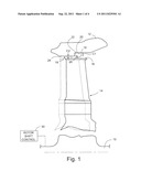
[0010] FIG. 1 is a side elevation, partly sectioned, showing a bucket tip clearance configuration in accordance with a first exemplary embodiment of the invention;
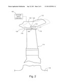
[0011] FIG. 2 is a side elevation similar to FIG. 1 but showing an alternative exemplary embodiment;
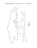
[0012] FIG. 3 is a simplified partial side section showing another exemplary embodiment of the invention; and
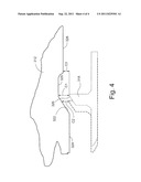
[0013] FIG. 4 is a simplified partial side section showing another exemplary embodiment of the invention.
DETAILED DESCRIPTION OF THE INVENTION
[0014] With reference to FIG. 1, the gas turbine rotor 10 is located concentrically within a turbine housing portion defined in part by a surrounding stator 12. The rotor 10 is typically formed with a plurality of axially-spaced wheels, each mounting an annular row of blades or buckets (one shown at 14) that extend radially outwardly toward the stator 12, substantially perpendicular to the axis of rotation of the rotor (or simply, "rotor axis"). The buckets 14 in a row of similar buckets on at least on of the wheels are provided with a tip shroud 16 which may be in the form of two or more arcuate segments, each segment extending circumferentially over two or more of the blades or buckets 14. Each of the tip shroud segments 16 may be formed with one or more radially outwardly extending seal teeth 18 that interact with the opposed surfaces of the stator to minimize the leakage of combustion gas across the gap between the tip shroud segments and the stator. For convenience, reference will be made herein simply to the "tip shroud", recognizing that the tip shroud may be constructed of two or more segments as described above.
[0015] In one exemplary but nonlimiting embodiment, the radially inwardly facing surface 19 of the stator 12 includes a first axial surface 20, a radial shoulder 22, and a second axial surface 24. In this embodiment, the radial shoulder 22 is oriented substantially 90 degrees relative to the first and second axial surfaces 20, 24. It will be appreciated that the axial surfaces 20 and 24 establish differential radial gaps between the tip shroud and the stator, and more specifically, between the tip of the seal tooth (or teeth) and the stator. In this exemplary embodiment, the rotor 10 and the row of buckets or blades 14 may be shifted axially (to the left) as shown in phantom in FIG. 1. By incorporating the stepped surfaces 20 and 24 on the stator, the seal tooth or teeth can move from an axial position within the large clearance gap portion C1 during transient conditions such as start-up and shut-down, or upon significant load changes, and move to the reduced, tighter clearance gap portion C2 when the turbine components reach (or return to) substantial thermal equilibrium.
[0016] Axial shifting of the rotor relative to all or part of a stationary stator may be achieved by any suitable mechanical (or electromechanical), hydraulic or pneumatic means 30 or 130, or by engineered differential thermal expansion properties of the selected rotor and stator materials, as would be understood by the ordinarily skilled worker in the art.
[0017] FIG. 2 represents an alternative exemplary embodiment of the invention. In FIG. 2, similar reference numerals are used to indicate corresponding components but with the prefix "1" added. Here, the rotor 110 remains stationary but the stator 112 can be shifted axially relative to the bucket tip shroud 116 and its seal tooth or teeth 118, to achieve the same result as described above in connection with FIG. 1. It will be appreciated that the outer sealing edge of the seal tooth may be substantially blunt and substantially parallel to the rotor axis (see edge 226 in FIG. 3), or formed to extend at an acute angle to the shroud tip (and to the rotor axis) as shown, for example, at 26 and 126 in FIGS. 1 and 2, respectively.
[0018] FIG. 3 represents another exemplary but nonlimiting embodiment of the invention. Reference numerals similar to those used in FIGS. 1 and 2, but with the prefix "2" added, are used in FIG. 3 to designate corresponding components. In this exemplary embodiment, the shoulder 222 connecting the axial surfaces 220 and 224 is sloped at an acute angle (for example, 45 degrees) relative to the surfaces 220, 224 and to the rotor axis. This arrangement provides a greater range of gap adjustability between the maximum and minimum clearances between the flat edge 226 of seal tooth 218 and the stator as the rotor is shifted axially relative to the stator (or vice versa). In the example shown, a relative axial shift of 0.50 inch (to the left as shown in FIG. 3) is required to move between a first large clearance gap of C1 and a second smaller clearance gap C2. The exact clearance gaps, required axial shift distance, etc. will vary depending on specific applications.
[0019] FIG. 4 represents a variation of FIG. 3 and similar reference numerals but with the prefix "3", are used to indicate corresponding components. Here, the seal edge 326 of the seal tooth 318 is formed at a 45 degree angle to the tip shroud (and to the rotor axis) so as to be substantially parallel with the sloped shoulder 322 of the stator 312. Note that for otherwise similar dimensional relationships, the angled seal edge 326 will produce the same clearance gap upon the same 0.50 inch axial shift as described above in connection with FIG. 3.
[0020] For the seal configurations in both FIGS. 3 and 4, the stator surfaces 228 and 328 to the right of the surfaces 320, 420, respectively, may provide for an intermediate clearance gap C3 (also achievable along the sloped shoulder 222, 322) in the event relative axial shifting of the rotor or stator in an opposite direction is permitted.
[0021] While the invention has been described in connection with what is presently considered to be the most practical and preferred embodiment, it is to be understood that the invention is not to be limited to the disclosed embodiment, but on the contrary, is intended to cover various modifications and equivalent arrangements included within the spirit and scope of the appended claims.
User Contributions:
Comment about this patent or add new information about this topic:
Images included with this patent application:
 |  |
 |  |
| New patent applications in this class: | |
| Date | Title |
|---|---|
| 2022-05-05 | Cooling method for a high-temperature radial gas turbine engine |
| 2019-05-16 | Controlling a wet gas compression system |
| 2018-01-25 | High pressure cyclonic separator for turbomachinery |
| 2018-01-25 | Systems and methods for cooling components within a gas turbine engine |
| 2018-01-25 | Engine, rotary device, power generator, power generation system, and methods of making and using the same |
| New patent applications from these inventors: | |
| Date | Title |
|---|---|
| 2014-02-20 | Creep life management system for a turbine engine and method of operating the same |
| 2013-02-21 | Use of motor protection system to assist in determining power plant metrics |
| 2012-10-25 | System and method for removing heat from a turbomachine |
| Top Inventors for class "Rotary kinetic fluid motors or pumps" | |
| Rank | Inventor's name |
|---|---|
| 1 | Gabriel L. Suciu |
| 2 | Frederick M. Schwarz |
| 3 | United Technologies Corporation |
| 4 | Brian D. Merry |
| 5 | Craig M. Beers |