Patent application title: Object Launching System and Method
Inventors:
Tim Taylor (North Canton, OH, US)
IPC8 Class: AA63F724FI
USPC Class:
273129 K
Class name: Surface projectile game; game element (e.g., target, etc.) or accessory therefor other than projectile, per se) projectors swung, carried by user
Publication date: 2011-09-08
Patent application number: 20110215525
Abstract:
Some embodiments relate to a base unit for use in a game. The base unit
includes a lower panel extending from a front region of the base unit
towards an inner region of the base unit, wherein the lower panel has a
scoring region associated therewith. The base unit also includes an upper
panel extending from a rear region of the base unit towards the inner
region of the base unit, wherein the upper panel has a launching assembly
coupled thereto. A sidewall extends upwardly from a lower sidewall region
to an upper sidewall region, wherein the lower sidewall region abuts the
lower panel at the inner region and wherein the upper sidewall region
abuts the upper panel at the inner region. Other embodiments are also
provided.Claims:
1. A base unit for use in a game, the base unit comprising: a lower panel
extending from a front region of the base unit towards an inner region of
the base unit, wherein the lower panel has a scoring region associated
therewith; an upper panel extending from a rear region of the base unit
towards the inner region of the base unit, wherein the upper panel has a
launching assembly coupled thereto; and a sidewall extending upwardly
from a lower sidewall region to an upper sidewall region, wherein the
lower sidewall region abuts the lower panel at the inner region and
wherein the upper sidewall region abuts the upper panel at the inner
region.
2. The base unit of claim 1: wherein the upper panel includes an elongate slot defined therein, and wherein the launching assembly comprises an object holder having a coupling member that slideably engages the elongate slot.
3. The base unit of claim 1, wherein the scoring region comprises at least one aperture.
4. The base unit of claim 1, wherein the upper panel is inclined at a first angle relative to a lower surface of the base unit.
5. The base unit of claim 4, wherein the lower panel is declined at a second angle relative to the lower surface of the base unit.
6. The base unit of claim 4, wherein the lower panel includes a face plate on which the scoring region is provided, wherein the lower panel is configured to interchangeably accept other face plates having other scoring regions.
7. The base unit of claim 4, wherein the lower panel includes a face plate on which the scoring region is provided, wherein the face plate rests on a ledge recessed with regards to an outer surface of the lower panel.
8. The base unit of claim 1, wherein the launching assembly further comprises pivot point about which the launching assembly can rotate.
9. The base unit of claim 1, wherein the launching assembly comprises a slide.
10. The base unit of claim 1, wherein the launching assembly comprises a catapult.
11. The base unit of claim 1, wherein the launching assembly comprises a torsion hammer.
12. The base unit of claim 1, wherein the launching assembly comprises a spring.
13. The base unit of claim 1, wherein the launching assembly comprises a pendulum.
14. The base unit of claim 1, wherein the launching assembly comprises a rubber band.
15. The base unit of claim 1, further comprising: a distance measuring element adapted to determine when the base unit is a predetermined distance from another object.
16. The base unit of claim 15, where the distance measuring element comprises: a string, chain, or other flexible or foldable element coupled to the base unit and exhibiting the predetermined distance.
17. A game system, comprising: a first base unit having a scoring region associated therewith; and a second base unit having a launching assembly configured to launch an object towards the scoring region of the first base unit.
18. The game system of claim 17, further comprising: a rotatable scoring assembly having first and second scoring regions corresponding to the first and second base units, respectively.
19. The game system of claim 17, wherein the first base unit comprises: a lower panel extending from a front region of the first base unit towards an inner region of the first base unit, wherein the scoring region is disposed on the lower panel; an upper panel extending from a rear region of the first base unit towards the inner region of the first base unit, wherein the upper panel has a launching assembly coupled thereto; and a sidewall extending upwardly from a lower sidewall region to an upper sidewall region, wherein the lower sidewall region abuts the lower panel at the inner region and wherein the upper sidewall region abuts the upper panel at the inner region.
20. The game system of claim 19: wherein the upper panel of the first base unit includes an elongate slot defined therein, and wherein the launching assembly of the first base unit comprises an object holder having a coupling member that slideably engages the elongate slot.
Description:
REFERENCE TO RELATED APPLICATIONS
[0001] This application claims priority to U.S. Provisional Application having Ser. No. 61/311,413, filed on Mar. 8, 2010, and entitled "Object Launching System and Method", which is incorporated by reference herein in its entirety.
FIELD
[0002] The present invention relates generally to games, and more particularly to games in which players use a launching assembly to attempt to launch an object into a predetermined scoring area.
BACKGROUND
[0003] Games have long been a source of enjoyment for children and adults. For example, checkers, chess, and a number of other games allow players to refine their skills and compete against other players in good-hearted fashion. There is an ongoing need for new games to capture the interest of children and adults.
[0004] Consequently, this disclosure provides new games as set forth herein.
BRIEF DESCRIPTION OF THE DRAWINGS
[0005] In the following drawings, which form a part of the specification and which are to be construed in conjunction therewith, and in which like reference numerals have been employed throughout wherever possible to indicate like parts in the various drawings.
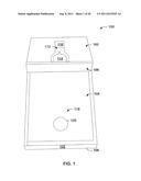
[0006] FIG. 1 is a perspective frontal photo of an object launching system constructed in accordance with an aspect of this invention;
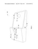
[0007] FIG. 2 is a perspective side photographic view of the object launching system of FIG. 1, according to yet another aspect of the present invention;
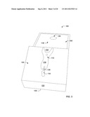
[0008] FIG. 3 is a perspective frontal photographic view of an object launching system constructed in accordance with an aspect of this invention;
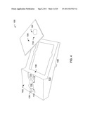
[0009] FIG. 4 is a perspective side photographic view of an object launching system with an inclined front panel removed;
[0010] FIG. 5 is a perspective bottom photographic view of an object launching system according to one aspect of the present invention;
[0011] FIG. 6 is a perspective bottom photographic view of an object launching system with the launching mechanism in a prelaunch position according to yet another embodiment of the invention;
[0012] FIG. 7 is a perspective bottom photographic view of an object launching system with the launching mechanism in a relaxed position according to yet another embodiment of the invention;
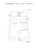
[0013] FIG. 8 is a perspective frontal photographic view of an object launching system with three holes in an inclined front panel constructed in accordance with an aspect of this invention;
[0014] FIGS. 9-15 are various views of launching mechanisms according to another embodiment of the invention;
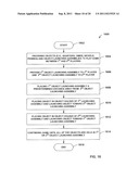
[0015] FIG. 16 is a flow diagram illustrating an example of a methodology for utilizing an object launching game in accordance with one or more aspects of the present invention;
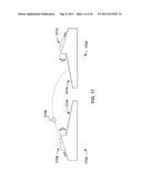
[0016] FIG. 17 depicts one example of how a first base unit can launch an object onto a scoring region of a second base unit in accordance with some manners of game play in accordance with the invention.
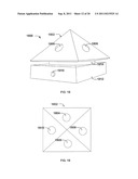
[0017] FIG. 18 illustrates a perspective view of a rotating scoring assembly, which may be referred to as "FOUR-PLAY®" in some contexts.
[0018] FIG. 19 illustrates a top view of a rotating scoring assembly, which may be referred to as "FOUR-PLAY®" in some contexts.
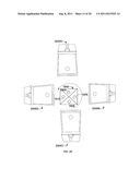
[0019] FIG. 20 depicts one example of how four different base units can attempt to launch an object into respective scoring regions of a rotating scoring assembly in accordance with some manners of game play in accordance with the invention.
[0020] FIG. 21 depicts several examples of different scoring regions that may be used in some embodiments.
[0021] FIG. 22 depicts several different perspective views of a support platform for deploying one or more base units to users.
[0022] FIG. 23 depicts a base unit with adjustable legs to provide an adjustable launch angle.
[0023] FIGS. 24A-24B depicts two different manners in which coins or other objects can be held in a launching assembly.
[0024] FIG. 25 depicts several different target aperture configurations.
[0025] FIG. 26 shows lower panels with various configurations.
[0026] FIG. 27 shows one example of a launching assembly that includes a pivot point.
[0027] FIG. 28 shows one example of another launching assembly for launching a coin.
DETAILED DESCRIPTION
[0028] One or more implementations of the present invention will now be described with reference to the attached drawings, wherein like reference numerals are used to refer to like elements throughout. The invention relates to an object launching system and associated method wherein a game is played utilizing the system and method.
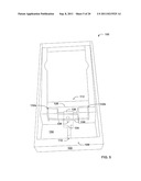
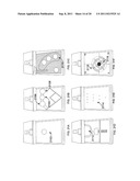
[0029] Several embodiments of a game that utilizes an object launching system of the present invention illustrated in FIGS. 1-8. FIGS. 1-8 collectively show a game base unit 100 that includes an upper panel 102, a lower panel 104, and a sidewall 106 intersecting the upper and lower panels. The upper panel 102 is inclined at an angle, a, relative to a lower surface 108 of the base unit 100, and includes at least one elongate slot 110 therein. A launching assembly 112 slidably engages the elongate slot 110 in the upper panel 102, wherein the launching assembly includes an object holder 114 and a finger pull 116. The lower panel 104 is declined at an angle, β, relative to the lower surface 108 of the base unit 100 and includes at least one scoring region 118, such as a target aperture 120 for example. Side panels 122 often extend downward from the upper and lower panels 102, 104 to define the lower surface 108 of the base unit 100.
[0030] As can be seen from the bottom of the base unit 100 (see FIGS. 5-7), the launching assembly 112 includes a coupling member 124 that extends through the elongate slot 110 so as to slidably couple the launching assembly 112 to the upper panel 102. A stop block 126, which is wider than the elongate slot 110, helps to vertically retain the launching assembly 112 near the upper panel 102. A cross block 128 and a side panel 122 are disposed at opposing ends of the elongate slot 110 to laterally retain the launching assembly near the upper panel 102.
[0031] To facilitate launching of an object, a rubber band 130 is fitted into a pair of slots 132a, 132b on an underside 134 of the upper panel 102. A fastener 136 protrudes from the stop block 126 and physically couples the rubber band 130 to the finger pull 116. To launch an object during game play, the object can be placed in the object holder 114 and launched by pulling the finger pull 116 with a backward motion 138 (FIG. 4). When the launching assembly 112 is an initial relaxed position (FIG. 5), the rubber band 130 is correspondingly in a relaxed position. As the launching assembly 112 is pulled backwards via the finger pull 116, the rubber band 130 is stretched so that it applies a forward bias to the launching assembly 112 (FIG. 6). Thus, when the finger pull 116 is released, the launching assembly 112 lurches forward until the stop block 126 hits the cross block 128 (FIG. 7), thereby ejecting the object from the object holder 114.
[0032] In addition, the launching assembly can be provided with a pivot, such that the angle at which the object is launched can be offset from the direction of the slot. For example, FIGS. Although a rubber band 130 is utilized in a preferred embodiment, there are many other force producing mechanisms that can be utilized to launch the object from the object holder 114, all of which are contemplated as falling within the scope of the present invention. A few alternative force producing mechanisms are discussed below, although it will be appreciated that these in no way limit the scope of the present invention.
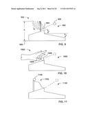
[0033] FIGS. 9-15 illustrate several alternative launching systems. FIG. 9 illustrates an object launching assembly 900 that utilizes a pendulum assembly 902. A player can drop a pendulum weight 904 from a height h from a flat surface 906, for example so that the pendulum weight 904 impacts with an object 908 to thereby launch the object 908.
[0034] FIG. 10 illustrates an object launching assembly 1000 utilizing a player's hand 1002 to launch an object 1008. For example, a player's finger 1009 is snapped outward so that the finger 1009 impacts with an object 1008 to thereby launch the object 1008 toward a second object launching assembly.
[0035] FIG. 11 further illustrates an object launching assembly 1100 utilizing a slide 1102 to thereby launch an object 1108. For example, the object 1108 can be released from the slide 1102 such that the object 1108 speeds off of the slide toward a second object launching assembly.
[0036] FIG. 12 illustrates another object launching assembly 1200 utilizing a catapult 1202 to thereby launch an object 1208.
[0037] FIG. 13 illustrates another object launching assembly 1300 utilizing a spring assembly 1302 to thereby launch an object 1308 toward a second object launching assembly, for example. For example the object 1308 is pulled backward so that a spring 1307 impacts with an object 1308 to thereby launch the object 1308 toward a second object launching assembly.
[0038] FIGS. 14-15 illustrate another object launching assembly 1400 utilizing a torsion spring hammer 1402 to thereby launch an object 1408 toward second object launching assembly, for example. FIG. 14 illustrates a top view of object launching assembly 1400, whereas FIG. 15 illustrates a side view of the object launching assembly 1400. It should be noted that object launching systems are well known by those of skill in the art and all such object launching systems are included in the present invention.
[0039] In some embodiments, base units (e.g., base unit 100 of FIG. 1) can be made of wood, however, base units can be made from other materials, including but not limited to: plastic, blow-molded components; plastic, injection molded components; components made of various woods (e.g., maple, pine, black walnut), metal, cardboard, composite materials, etc.
[0040] In some embodiments, a base unit can include a target aperture that allows objects to enter or pass through the aperture and them "traps" the objects in a storage bin included in the base unit. In one embodiment, for example objects have to be removed via a hinged door, rather than an aperture. In another embodiment, the base unit automatically keeps track of and displays running scores based on which of several apertures the objects enter. The scores can be kept mechanically, electronically or the like. In addition, numerous inclined panels can be utilized with any number and arrangement of apertures. Also, an electronic rotatable blocking component can be rotated in front of the apertures thereby blocking the aperture opening at times.
[0041] In accordance with another aspect of the present invention, FIG. 16 illustrates a method 1600 for playing a game that utilizes one or more base units (e.g., base unit 100 as illustrated in FIG. 1). While exemplary methods are illustrated and described herein as a series of acts or events, it will be appreciated that the present invention is not limited by the illustrated ordering of such acts or events, as some steps may occur in different orders and/or concurrently with other steps apart from that shown and described herein, in accordance with the invention. In addition, not all illustrated steps may be required to implement a methodology in accordance with the present invention. Moreover, it will be appreciated that the methods may be implemented in association with the systems illustrated and described herein as well as in association with other systems not illustrated and/or described.
[0042] As illustrated in FIG. 16, the method 1600 begins at 1602 and at 1604 when a first object launching assembly (e.g., a first base unit 100) and a second object launching assembly (e.g., a second base unit 100) are provided. In this embodiment, the object launching assemblies are fully enclosed with a bottom plate and a door for removing coins. The players can bring numerous objects to play with, however in this embodiment the players, for example, each bring ten dollars in change (i.e., quarters, dimes, nickels). The change is placed on a table for example next to each player.
[0043] At 1606 the first player and the second player can claim the object launching assemblies so that each of the players is launching objects toward his own object launching assembly. Although this embodiment is being described with respect to the game being played with two players, any number of players can play at the same time, for example.
[0044] At 1608 a first object launching assembly 102 is spaced away from a second object launching assembly by defined distance, wherein the defined distance is maintained, for example by a string, a chain, a wire and the like attached to the front of each object launching assembly. Although this embodiment is described with a defined distance it is also contemplated that the game can be played with numerous defined or undefined distances between the various object launching assemblies.
[0045] At 1610, the first player places an object (e.g., a quarter) in an object holder and launches the object toward a first object launching assembly aperture. If the first player successfully gets the object in the aperture the first player launches another object toward the first object launching assembly. Once the first player is unsuccessful in his attempt to get an object into an aperture the second player places an object (e.g., a quarter) in an object holder at 1612 and launches the object toward a second object launching assembly aperture. The players go back and forth trading turns until all of the objects are captured in one of the object launching assemblies at 1614 wherein the game ends at 1616.
[0046] In one embodiment, a base unit can measure approximately 5 inches by 12 inches. However, in other embodiments base units can be small enough to fit on a key chain (e.g., a base unit measuring about 2 inches by 3.5 inches), or large enough to launch large objects, such as basketballs; and all sizes of base units are contemplated as falling within the scope of the present invention.
[0047] FIG. 17 shows one manner in which a first base unit 1702 and second base unit 1704 can interact with one another during game play. As shown, the first base unit 1702, under the control of a user (not shown), can launch an object 1706 from its launching assembly 1708 towards the scoring region 1710 of the second base unit 1704. If the user lands the object in the scoring region 1710, the user of the first base unit scores. The second base unit 1704 can similarly launch an object from its launching assembly 1712 towards a scoring region 1714 on the first base unit 1702. In one embodiment, the players can go back and forth trading turns until all of the objects are captured in one of the base units wherein the game ends.
[0048] As can be appreciated from the method of FIG. 16, in other embodiments a user can shoot objects towards a scoring area on his own base unit. Thus, some embodiments of the game do not require multiple players and can be played in a solitaire-like fashion.
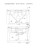
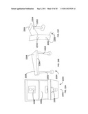
[0049] FIGS. 18-19 show one embodiment of a rotatable scoring assembly 1800, which may be used in some implementations. FIG. 18 shows a perspective side view, and FIG. 19 shows a top view. In this embodiment, the rotatable scoring assembly 1800, which may also be referred to as "FOUR-PLAY®" in some contexts, includes a pyramid 1802 having one or more apertures (e.g., 1804, 1806, 1808, and 1810) on each side. The pyramid 1802 is disposed on a base 1812 having a rotating turn-table 1814. The base 1812 has a user control interface, such as an on/off pushbutton 1816, and/or a speed control element (not shown) for controlling the rotational speed of the turntable 1814 and the pyramid 1802.
[0050] During FOUR-PLAY® game play, as shown in FIG. 20, a number of users control a number of base units 2000A-2000D and attempt to score by launching respective objects towards respective pre-determined scoring regions assigned to them on the rotating scoring assembly 1800. In one embodiment, each user attempts to score by launching an object from their base unit into a scoring region (e.g., aperture) uniquely assigned to them on the rotating scoring assembly. For example, in FIG. 20, first base unit 2000A could be assigned to score in first aperture 1804, second base unit 2000B could be assigned to score in second aperture 1806, third base unit 2000C could be assigned to score in third aperture 1808, and fourth base unit 2000D could be assigned to score in fourth aperture 1810; whereby each base unit scores a point when it passes an object through its respective aperture. In another embodiment, each user attempts to score by launching an object from their base unit into a scoring region (e.g., aperture) uniquely assigned to at least one other user; whereby each user decrements the other users' score when it passes its object into/through the other users' scoring region. For example, first base unit 2000A could be assigned to score in second, third, and fourth apertures (1806, 1808, 1810); second base unit 2000B could be assigned to score in first, third, and fourth apertures (1804, 1808, 1810); and so on. Other scoring scenarios are also possible. As the turntable rotates the pyramid of the rotating scoring assembly 1800, users will find enjoyment attempting to score points in these or other manners, due to the competitive nature of the game and camaraderie developed therewith.
[0051] Although FIGS. 19-20 show a rotating scoring assembly 1800 that is pyramidal shaped, it will be appreciated that other geometries are also contemplated. For example, in other embodiments, the rotating scoring assembly have a cylindrical surface extending upwardly around an axis extending into the top surface of the turn-table. Apertures could then be defined in the cylindrical surface, for example in a spiral pattern or in any other pattern. Again, the apertures or other scoring regions could be assigned in various manners to the users so that points can be scored in various manners. Other geometries are also contemplated, and may incorporate any number of players, different heights or levels, and different surface geometries.
[0052] FIG. 21A-21F (collectively FIG. 21) shows several different embodiments of different scoring regions that are contemplated as falling within the scope of this disclosure. These embodiments are merely examples, and are not held to be limiting in any manner. In FIG. 21A, one can see a somewhat basic scoring region that comprises a single aperture 2102 on the lower panel of a base unit. The aperture is approximately centrally located in the lower panel, and is sufficiently large so that a coin or other suitable table-top object can be launched therethrough.
[0053] In FIG. 21B, one can see another scoring region that comprises three apertures superimposed over a graphical representation of a baseball diamond. A smaller, middle aperture 2104 is positioned between two larger, side-apertures (2106, 2108). The middle aperture is labeled "grand slam" and the side-apertures are labeled "out", thereby allowing one or more users to launch objects to simulate a baseball game in some respects.
[0054] FIG. 21C shows another scoring region having multiple aperatures 2110 that simulate a golf hole. A portion of the lower panel corresponding to green grass can be covered with a "fuzzy" surface (e.g., felt, some other fabric) or another frictional surface, while a portion of the lower panel corresponding to a sand trap, for example, can be covered with sand or some other material that differs from the grass.
[0055] FIG. 21D shows another scoring region that simulates a football field, in which the users score points by successfully launching an object through a "goalpost" aperature 2112 that extends vertically from the lower panel.
[0056] FIG. 21E shows yet another scoring region that simulates bowling, where a number of pins 2114 are set on the lower scoring region.
[0057] FIG. 21F shows yet another scoring region wherein the lower panel is marked with a number of target zones (e.g., 2116, 2118) having different point values. In this embodiment, another user attempts to launch his or her object onto the target zone with the highest score value. As objects are launched, point values are accrued until some threshold is crossed that indicates one user is the winner.
[0058] It will be appreciated that these lower panels of FIG. 21 are merely examples of but a few embodiments of how scoring regions can be implemented. Often, the lower panels are removable from the base units so that a user can purchase multiple lower panels and interchange them to gain further enjoyment from the gaming system.
[0059] FIG. 22 (FIG. 22A-22C collectively) shows a support platform 2200 on which one or more base units can be mounted. This support platform 2200 provides a convenient arrangement for deploying one or more base units to bars, restaurants, homes, and the like, so that users can interface with the game system in a consistent manner. The support platform 2200 includes one or more legs 2202, as well as a substantially horizontal lateral member 2204. A first base unit 2206, which includes a launcher assembly, is mounted (either detachably or permanently) near a first end of the support platform 2200. Near the other end of the support platform, another base unit or merely a scoring region 2208 can be disposed. An object receptacle bin 2210 (e.g., a coin box with a lock and key assembly) can be disposed in the other end of the support platform in some embodiments to generate revenue for a bar or restaurant, for example. Often, the support platform 2200 can include audio and/or visual displays (e.g., lights and/or sounds) to enhance a user's experience while playing. For example, the support platform 2200 can include a sensor near the other end of the platform that indicates when a user scores, and can light up a scoreboard or some other visual display to indicate the user has scored, thereby enhancing game play for the user.
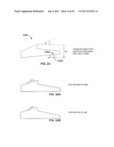
[0060] FIG. 23 shows one example of a base unit 2300 having an adjustable launch angle, Δα. In this embodiment, an adjustable (e.g., rotatable) leg 2302, which rotates about a pivot point 2304. To adjust the launch angle by an amount, Δα, a user can correspondingly adjust the leg to correspondingly adjust the height of the launching assembly and thus, the launch angle. In other embodiments, other mechanisms could be used to alter the launch angle, such as a wedge or a series of shims, a threaded height pedestal, for example.
[0061] FIGS. 24A-24B show two examples of how objects (e.g., coins) can be held in a launch assembly. In FIG. 24A, a coin is held on its edge, and in FIG. 24B a coin is held on its face.
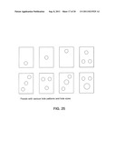
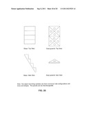
[0062] FIG. 25 shows a few examples of various hole configurations. As shown, the holes can have different sizes and different locations to form a scoring region on a lower panel. It will be appreciated, however, that holes are not required to implement a scoring region and that some scoring regions do not include holes.
[0063] FIG. 26 shows some other examples of more complex scoring regions. As shown, some scoring regions can include a series of steps, wherein different steps can be assigned different point values for example. Other scoring regions can include a series of one or more pyramids (e.g., dual pyramids), or other multi-faceted manifolds that make game play more challenging.
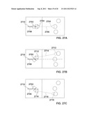
[0064] FIGS. 27A-27C show another example where a launching assembly includes a pivot point 2702 about which the launching assembly can be rotated to launch an object at different angles. For example, FIG. 27A shows an example where an object 2704 is launched on a launch path 2706 that is aligned to a line 2708 of an elongated slot 2710. FIG. 27B shows an example where an object 2712 is launched on a launch path 2714, wherein the launch path 2714 is disposed at a positive angle α2 (e.g., about 15 degrees) with respect to the line 2708 of the elongated slot 2710. FIG. 27C shows an example where an object 2716 is launched on a launch path 2718, wherein the launch path 2718 is disposed at a negative angle α3 (e.g., about negative 15 degrees) with respect to the line 2708 of the elongated slot 2710.
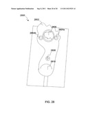
[0065] FIG. 28 shows another example of a launching assembly 2800. This launching assembly includes a launching plate 2802 that includes two or more members 2804a, 2804b between which a coin 2806 or other object is positioned. In the illustrated embodiment, the launching plate 2802 is generally in the shape of a foot, but could also take other forms in other embodiments. A coupling member 2808 extends through the launching plate 2802 such that the launching assembly can slideably engage a base unit (not shown). A bulbous finger pull 2810 is included near the heel of the foot.
[0066] Although the invention has been illustrated and described with respect to one or more embodiments, implementations, alterations and/or modifications may be made to the illustrated examples without departing from the spirit and scope of the appended claims. In particular regard to the various functions performed by the above described components or structures (assemblies, devices, systems, etc.), the terms (including a reference to a "means") used to describe such components are intended to correspond, unless otherwise indicated, to any component or structure which performs the specified function of the described component (e.g., that is functionally equivalent), even though not structurally equivalent to the disclosed structure which performs the function in the herein illustrated exemplary implementations of the invention. In addition, while a particular feature of the invention may have been disclosed with respect to only one of several implementations, such feature may be combined with one or more other features of the other implementations as may be desired and advantageous for any given or particular application. Furthermore, to the extent that the terms "including", "includes", "having", "has", "with", or variants thereof are used in either the detailed description and the claims, such terms are intended to be inclusive in a manner similar to the term "comprising".
User Contributions:
Comment about this patent or add new information about this topic:
Images included with this patent application:
 |  |
 |  |
 |  |
 |  |
 |  |
 |  |
 |  |
 |  |
 |  |
 |  |
| Similar patent applications: | |
| Date | Title |
|---|---|
| 2010-08-12 | Multiple objects location apparatuses and systems, and location methods and error adjustment methods thereof |
| 2009-06-04 | Liquid projectile launching and detecting devices and set thereof |
| 2009-01-08 | Roulette gaming machine changing payout ratio set for each bet type and playing method of roulette game |
| 2010-03-18 | Reusable card-based gaming system and method |
| 2010-10-07 | Puzzle-based wagering game system and method |
| Top Inventors for class "Amusement devices: games" | |
| Rank | Inventor's name |
|---|---|
| 1 | Attila Grauzer |
| 2 | Peter Krenn |
| 3 | Ronald R. Swanson |
| 4 | Kyle Bateman |
| 5 | Feraidoon Bourbour |