Patent application title: Systems and Methods for Dynamic FeedForward
Inventors:
Daryush Agahi (Irving, CA, US)
IPC8 Class: AG05D1620FI
USPC Class:
700282
Class name: Specific application, apparatus or process mechanical control system flow control (e.g., valve or pump control)
Publication date: 2011-06-16
Patent application number: 20110144813
Abstract:
In some embodiments, a method of using feedforward to control a system
component may include determining if a feedforward term exists in a
feedforward table for a received operating set point. If a feedforward
term does not exist, the system component may be incremented until the
system to within a first acceptable tolerance of the desired set point.
In some embodiments, a measure of steady state error may be determined
and compared to a second acceptable tolerance. If within the acceptable
tolerance, the corresponding feedforward term may be recorded in the
feedforward table. In some embodiments, if the feedforward term exists
for the operating set point, the system component may be controlled using
controller output that corresponds to the feedforward term. When a change
to the system is detected that is associated with possible changes to the
feedforward values, new feedforward values may be generated for the
feedforward table.Claims:
1. A method, comprising: subdividing an operating range of a system
component into two or more set points or set point regions of operation;
creating a feedforward table for mapping feedforward terms to the two or
more set points or set point regions of operation; receiving an operating
set point; determining if a feedforward term exists for the operating set
point; if the feedforward term does not exist for the operating set
point, incrementing a system component as needed using controller output
to move the system to within a first acceptable tolerance of the desired
set point; determining if a measure of steady state error for the system
is within a second acceptable tolerance; if the measure of steady state
error for the system is within the second acceptable tolerance, recording
the corresponding feedforward term in the feedforward table for the
current set point; if the measure of steady state error for the system is
not within the second acceptable tolerance, not recording the
corresponding feedforward term in the feedforward table for the current
set point; if the feedforward term does exist for the operating set
point, controlling the component using controller output that corresponds
to the feedforward term associated with the desired set point to move the
system toward the desired set point; and when a change to the system is
detected that is associated with possible changes to the feedforward
values, generating one or more new feedforward values for the feedforward
table.
2. The method of claim 1, wherein the change to the system that is associated with a possible change to the feedforward value includes a change in temperature.
3. The method of claim 1, wherein generating new feedforward values when a change to the system is detected includes recording a new feedforward value if a measure of steady state error for the system is within the second acceptable tolerance when the system is subsequently within a first acceptable tolerance of the desired set point.
4. The method of claim 1, wherein determining the measure of steady state error for the system comprises calculating a standard deviation and a mean of multiple samples of controller output during the time the system is within the first acceptable tolerance of the desired set point, wherein the determined measure of steady state error for the system is the standard deviation divided by the mean.
5. The method of claim 1, wherein the first acceptable tolerance is approximately in a range of 0.1 to 0.4.
6. The method of claim 1, wherein the operating set point is a reservoir pressure and wherein the controller output and feedforward terms comprise valve positions of a valve coupled to a reservoir.
7. The method of claim 1, wherein the set point operating range is a range of reservoir pressures.
8. The method of claim 1, wherein the system is a surgical system and wherein the set point is received through a touchscreen or footswitch of a surgical console.
9. The method of claim 1, wherein the operating range is subdivided according to a resolution provided by a user of the system.
10. The method of claim 1, wherein the feedforward table is not populated prior to operating the system component and wherein the feedforward terms are determined and used to populate the feedforward table during subsequent system component operation.
11. The method of claim 1, wherein the feedforward table is populated prior to operating the system component with calculated or default feedforward terms and wherein updated feedforward terms are determined and used to overwrite existing feedforward terms in the table during subsequent system component operation.
12. A method of using a feedforward table to control a surgical system component, comprising: receiving an operating set point; determining if a feedforward term exists in the feedforward table for the operating set point, wherein the feedforward table comprises a plurality of set points; if the feedforward term does not exist for the operating set point, incrementing the system component as needed using controller output to move the system to within a first acceptable tolerance of the desired set point; determining if a measure of steady state error for the system is within a second acceptable tolerance; if the measure of steady state error for the system is within the second acceptable tolerance, recording the corresponding feedforward term in the feedforward table for the current set point; if the measure of steady state error for the system is not within the second acceptable tolerance, not recording the corresponding feedforward term in the feedforward table for the current set point; if the feedforward term does exist for the operating set point, controlling the component using controller output that corresponds to the feedforward term associated with the desired set point to move the system toward the desired set point; when a change to the system is detected that is associated with possible changes to the feedforward values, generating one or more new feedforward values for the feedforward table.
13. The method of claim 12, wherein the change to the system that is associated with a possible change to the feedforward value includes a change in temperature.
14. The method of claim 12, wherein generating new feedforward values when a change to the system is detected includes recording a new feedforward value if a measure of steady state error for the system is within the second acceptable tolerance when the system is subsequently within a first acceptable tolerance of the desired set point.
15. The method of claim 12, wherein determining the measure of steady state error for the system comprises calculating a standard deviation and a mean of multiple samples of controller output during the time the system is within the first acceptable tolerance of the desired set point, wherein the determined measure of steady state error for the system is the standard deviation divided by the mean.
16. The method of claim 12, wherein the operating set point is a reservoir pressure and wherein the controller output and feedforward terms comprise valve positions of a valve coupled to a reservoir.
17. The method of claim 12, wherein the system is a surgical system and wherein the set point is received through a touchscreen or footswitch of a surgical console.
18. The method of claim 12, wherein the feedforward table is not populated prior to operating the system component and wherein the feedforward terms are determined and used to populate the feedforward table during subsequent system component operation.
19. The method of claim 12, wherein the feedforward table is populated prior to operating the system component with calculated or default feedforward terms and wherein updated feedforward terms are determined and used to overwrite existing feedforward terms in the table during subsequent system component operation.
Description:
FIELD OF THE INVENTION
[0001] The present invention generally pertains to control algorithms. More particularly, but not by way of limitation, the present invention pertains to dynamic feedforward.
DESCRIPTION OF THE RELATED ART
[0002] Complex systems, such as surgical consoles, may include many different components that interact with each other and the environment. Controlling these systems (e.g., in view of received user input or a programmed response) may require control systems that manipulate the components to achieve the desired performance. Often these control systems may control many different components and use input from several different sources (e.g., user input, sensor input, etc).
SUMMARY
[0003] In various embodiments a method of using feedforward to control a system component may include subdividing an operating range of the system component into two or more set points or set point regions of operation, creating a feedforward table for mapping feedforward terms to the set points of operation, receiving an operating set point, and determining if a feedforward term exists for the operating set point. If a feedforward term does not exist for the operating set point, the system component may be incremented as needed using controller output to move the system to within a first acceptable tolerance of the desired set point. In some embodiments, a measure of steady state error for the system may be determined and compared to a second acceptable tolerance. If the measure of steady state error for the system is within the acceptable tolerance, the corresponding feedforward term may be recorded in the feedforward table for the current set point. If the measure of steady state error for the system is not within the second acceptable tolerance, the corresponding feedforward term may not be changed in the feedforward table.
[0004] In some embodiments, if the feedforward term exists for the operating set point, the system component may be controlled using controller output that corresponds to the feedforward term associated with the desired set point in the feedforward table to move the system toward the desired set point. When a change to the system is detected that is associated with possible changes to the feedforward values (e.g., a change in system temperature), new feedforward values may be generated for the feedforward table.
BRIEF DESCRIPTION OF THE DRAWINGS
[0005] For a more complete understanding of the present invention, reference is made to the following description taken in conjunction with the accompanying drawings in which:
[0006] FIGS. 1a-b illustrate a flowchart of a feedforward method, according to an embodiment;
[0007] FIGS. 2a-c illustrate embodiments of feedforward tables;
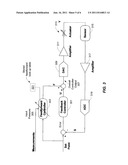
[0008] FIG. 3 illustrates a schematic of a system implementing feedforward, according to an embodiment; and
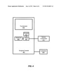
[0009] FIG. 4 illustrates a surgical console, according to an embodiment.
[0010] It is to be understood that both the foregoing general description and the following detailed description are exemplary and explanatory only and are intended to provide a further explanation of the present invention as claimed.
DETAILED DESCRIPTION OF THE EMBODIMENTS
[0011] Surgical consoles may include a range of systems (e.g., pneumatic systems, fluidics systems, etc.) used to support functionality for various surgical devices (e.g., vitrectomy probe, phacoemulsification handpiece, etc). The surgical console may use one or more control systems (e.g., which include one or more controllers) to control and monitor different aspects of these systems. For example, control systems may collect data about a system (e.g., through user input, through one or more sensors, etc.) and send control signals (e.g., a valve position) within the system to achieve a desired performance parameter near a set point (e.g., a user requested or system desired performance parameter such as a desired pressure for an accumulator tank). In some embodiments, the set point may be received from a user (e.g., a desired pressure set by a footswitch) or may be a preprogrammed/default system set point (other sources of set points are also possible). In some embodiments, the control system may control the system, for example, by outputting a signal to move an actuator, move a valve, increase power output, etc.
[0012] In some embodiments, the control system (e.g., through feedback controller 301 as seen in FIG. 3) may change the system in increments (e.g., move the valve by an incremental percentage such as 1% open or by a positional increment such as 1 degree rotation). Other increment types are also possible. In some embodiments, a user may set the size of the increment or the increment size may be a predetermined default (a larger increment resolution may result in faster changes than a smaller increment, but may result in a higher probability of overshooting/undershooting the target). In some embodiments, the increments may be variable (e.g., the system may use smaller increments as the system gets closer to the target set point). After incrementing a system component, the control system may obtain new data (e.g., obtain a resulting pressure measurement from a pressure sensor). The system may determine if an additional adjustment is needed and may output a corresponding control signal (e.g., to move the valve by an additional incremental percentage (or undo a previous incremental move)). In some embodiments, the system may stop incrementing when the system is within a tolerance of the target set point. The tolerance may be received from a user or preprogrammed into the system. This type of control may be characterized as a closed control loop. The size of the increment and the frequency of the change may result in faster or slower system response times with corresponding higher or lower overshoot/undershoot (which may affect system steady state error). In some embodiments, the control system may continuously monitor various system parameters and make adjustments as needed to maintain one or more performance parameters within a range of the desired performance parameters.
[0013] In some embodiments, the control system (e.g., through the feedforward controller 303 as seen in FIG. 3) may also use feedforward in its control algorithms to improve various performance parameters and produce a system output that follows a desired trajectory. For example, a control system may store values of various system components at given set points so that the control system may quickly direct system components to a predetermined value when a set point is requested. For example, if a pressure of X psi is requested, and, after several incremental changes to a proportional valve, the control system determines a pressure of X psi has been reached, the control system may store a position of the valve that corresponds to X psi such that if X psi is requested again in the future, the control system may initially direct the valve to the stored position. While the control system may still measure the pressure and determine if an incremental change is needed after the valve is placed in the stored position, the overall system response time may be faster than if the system had started incrementing the valve from its original position without first jumping to the stored position. As an example, if the control system determines that a pressure of 50 psi (pounds per square inch) is achieved when an inlet valve is in a 50% open state, the next time a set point of 50 psi is requested, the control system may direct the valve to 50% open (which may save several iterations of incremental change and re-measuring). In some embodiments, the system may store a controller output (such as valve position) for a range of set points (e.g., store 50% open to correspond to set points between 45-55 psi) such that when a set point is requested, the system can look up a controller output corresponding to the range that the set point falls within. Directing a system component according to a stored value may result in a faster system response time to the requested set point. In some embodiments, stored valve positions (or other controller output) for multiple set points may be stored as feedforward terms along with their corresponding set points in one or more feedforward tables.
[0014] In some embodiments, the feedforward tables may be dynamically and continuously updated to compensate for changes (e.g., environmental changes, changes to system parameters or behavior, etc.) to the system over time. For example, as the system heats up or is used for an extended period, a position of 50% open for the valve may no longer correspond to a pressure of 50 psi (e.g., increased system heat may result in higher overall pressure such that a position of 40% open may correspond to 50 psi after 5 minutes of continuous operation). The feedforward tables may thus be updated with new feedforward terms as needed to adapt the system to change.
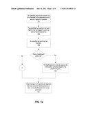
[0015] FIGS. 1a-b illustrate a flowchart of a feedforward method, according to an embodiment. The elements provided in the flowchart are illustrative only. Various provided elements may be omitted, additional elements may be added, and/or various elements may be performed in a different order than provided below.
[0016] At 101, an operating range of the system may be subdivided into several potential set points or set point regions corresponding to system operation. In some embodiments, the operating range of a performance parameter for a system (e.g., pressure, position, speed, etc.) may be divided into a user provided or system determined number of points or regions. For example, if a system pressure operates over a range of 0 psi to 100 psi and a user or the system requests 10 regions, the subdivided regions may include: 0-10 psi, 11-20 psi, 21-30 psi, 31-40 psi, 41-50 psi, 51-60 psi, 61-70 psi, 71-80 psi, 81-90 psi, and 91-100 psi. This is only one example, other variables and other resolutions are also contemplated. For example, an operating range of 0 to 5 volts (V) may be subdivided into 100 regions (0-0.05 V, 0.06-0.10 V, . . . ). In some embodiments, specific values may be used instead of or in addition to regions. For example, the operating pressure of 0 psi to 100 psi may include: 10 psi, 20 psi, 30 psi, 40 psi, 50 psi, 60 psi, 70 psi, 80 psi, 90 psi, and 100 psi. In some embodiments, the points/regions may not be equally subdivided. For example, certain regions of the operating range may be subdivided with a greater resolution than other regions. As an example, the 10 regions for the operating pressure of 0 psi to 100 psi may include: 0-15 psi, 16-30 psi, 31-45 psi, 45-47 psi, 48-50 psi, 51-52 psi, 53-55 psi, 56-70 psi, 71-85 psi, and 86-100 psi. Different resolutions in different parts of the range may allow finer control in portions of the range that are operated in more frequently.
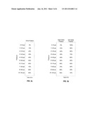
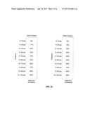
[0017] At 103, the subdivided set points or set point regions may be mapped via a look-up table to feedforward terms (controller outputs). FIG. 2a illustrates an example of a look-up table 201a with the subdivided operating range (in this case, pressure) mapped to corresponding feedforward terms (in this case, valve position in percent open state). In some embodiments, the subdivided set points or set point regions may be mapped to multiple feedforward terms. FIG. 2b illustrates an example of a look-up table 201b with the subdivided operating range mapped to corresponding multiple feedforward terms (in this case, input valve position and exit valve positions in percent open state). For example, when a set point of 45 psi is requested, the system may use initial controller outputs of 40% input valve position and 60% exit valve position. In some embodiments, the subdivided set points or set point regions may be mapped to multiple look-up tables (e.g., each with different variables or each relevant to a particular system operating mode/condition). FIG. 2c illustrates an example of two look-up tables, one look-up table 201c with subdivided operating range mapped to feedforward terms to use if the pressure is increasing and a second look-up table 201d to use if the pressure is decreasing. In some embodiments, the feedforward terms may be pre-populated (e.g., according to factory defaults, a prior system run, etc). For example, all of the feedforward terms may be set to 0. In some embodiments, the feedforward terms may be populated/updated in the look-up table as the system operates (see below).
[0018] At 105, an operating set point may be received. For example, an operating parameter (e.g., pressure, position, speed, etc.) may be received from a surgical console, footswitch, keyboard, etc. The set point may be received as a user input or may be received as part of a program (e.g., an executing surgical program may direct different set points during different parts of a surgical procedure). In some embodiments, the control system may access a corresponding feedforward table to determine if a feedforward term exists for the requested set point.
[0019] At 107, if a feedforward term does not already exist, the control system may increment a corresponding component (e.g., move a valve) to move the system toward the desired set point. The control system may continue to receive relevant measurements (e.g., pressures, temperatures, etc.) and continue to reevaluate whether to increment the component again, undo the previous increment, or not increment the component. In some embodiments, incrementing procedures (e.g., increment sizes and directions relative to measured system parameters) may be preprogrammed into the control system. For example, a controller of the control system may be programmed to close a valve incrementally to reduce system pressure.
[0020] At 109, the control system may determine if the set point has been reached. For example, relevant system measurements (e.g., obtained by system sensors) may be compared to the set point (e.g., pressure in a chamber compared to the desired set point pressure) to determine if the relevant system measurement is within a tolerance of the desired set point (e.g., measured pressure within +/-1%, +/-1 psi, etc. of desired set point pressure). Other ranges are also contemplated (e.g., +/-5%, +/-10%, etc). The tolerance may be user provided, predetermined, system default, etc.
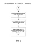
[0021] At 111, when the system is within an acceptable tolerance of the set point, the system steady state error may be determined. In some embodiments, the controller may continue to receive system measurements (e.g., sensor values) and may continue to provide controller output to a relevant system component even after the initial set point is achieved within the tolerance. For example, the controller may provide output on a periodic basis (e.g., every 0.1 seconds). Other periodic time periods are also contemplated. In some embodiments, the controller output may be substantially the same while the controller is maintaining the desired set point. However, in some cases, the controller may vary the controller output to compensate for system fluctuations. In some embodiments, determining a system steady state error may include comparing a mean of multiple samples of the controller output (e.g., valve position) to a standard deviation of the controller output. The number of samples to use for the comparison may be predetermined (e.g., 100) or samples for the comparison may continue to be accrued until the next set point change (e.g., when a user inputs a new set point).
[0022] At 113, if a measure of steady state error (e.g., a ratio of standard deviation to the mean of the accrued samples of the controller output) is within an acceptable range, the feedforward table may be updated with the value of the mean of the controller output (or another relevant system value). For example, if the standard deviation of the sampled controller output divided by the mean of the sampled controller output is <a predetermined value (e.g., 0.1, 0.4, etc.), the feedforward table may be updated with the value of the mean of the controller output. Other measures of steady state error are also possible (e.g., based on comparisons of variance to mean). Other criteria for storing a feedforward term are also contemplated. For example, if a feedforward term does not yet exist for the set point, a mean of the controller output for the set point may be automatically entered without determining a measure of steady state error. As another example, the system may determine whether to keep the controller output based on the standard deviation and/or mean of a sensor measurement (e.g., based on a determination of how steady the system pressure is during the controller output).
[0023] At 115, if the feedforward term exists for the desired set point, the feedforward term may be used as the initial system controller output for the desired set point. The controller may receive data (such as sensor data) to determine if additional adjustments need to be made to reach the desired set point (or come within an acceptable tolerance of the set point). In some embodiments, the feedforward term may be updated if additional adjustments are needed and/or the system steady state error is within an acceptable tolerance.
[0024] At 117, when changes to the system are detected that may cause the feedforward terms in the table to be in steady state error (e.g., if the detected temperature of the system changes), new feedforward terms may be determined (e.g., going forward) for the set points in the table. For example, if the system temperature changes more than X degrees (e.g., where X may be a user input or system default) the feedforward terms may be flagged, set to a default value, etc. Determining when to replace feedforward terms may be based on other system characteristics (e.g., operating time, system mode, type of tool being used, etc). In some embodiments, when a decision is made to replace the feedforward terms the previous feedforward terms may continue to be used as initial controller outputs but may be flagged for replacement when a new feedforward value can be determined (e.g., based on a mean of subsequent controller outputs for the corresponding set point). Thus the dynamic and continuous updating of feedforward terms may compensate for changes in the system or environmental conditions (e.g., temperature and pressure) resulting in faster response times and better tracking. In some embodiments, new feedforward terms may be calculated each time a set point is entered (e.g., each time the system reaches a set point value and the measure of steady state error is within an acceptable tolerance, the corresponding controller output (or mean of the controller output) may be used to update the corresponding feedforward term for that set point in the feedforward table).
[0025] In some embodiments, the feedforward method described in FIGS. 1a-b may be used to control pressure of an accumulator tank (or other reservoir) by controlling a proportional valve that supplies the accumulator tank. In some embodiments, one or more feedforward look-up tables (e.g., as seen in FIG. 2) may be created (e.g., table 201 for increasing output and table 203 for decreasing output). In some embodiments, the valve may have non-linear behavior as a function of the pressure drop across the valve (input pressure-set point) resulting in different feedforward values for the different input pressures. In some embodiments, two tables may be used to compensate for increased hysteresis in a valve output (e.g., the valve may experience dynamic-behavior changes as a function of temperature over time such that one table may be used when the input pressure is increasing and one table used when the input pressure is decreasing). In some embodiments, a range of set points may be divided into a number of segments depending on a desired resolution (e.g., in this example, 20 segments may be used to achieve a resolution of approximately 5%). Other numbers of segments and other resolutions are also possible (e.g., 1%). When a new set point is utilized by the system, the overall controller output may be averaged over a number of samples when the output reaches the desired set point (or, for example, within an error tolerance of the set point):
S K = set point closest to the table entry K ( where K may be provided as a selected point or range of points provided in the table ) ##EQU00001## U K i = controller output ( e . g . , actuating signal for a valve being controlled ) needed to maintain setpoint S K at time instant for sample i ##EQU00001.2## T K + = the feedforward table entry corresponding to S K in the positive direction ##EQU00001.3## T K - = the feedforward table entry corresponding to S K in the negative direction ##EQU00001.4## T K + = 1 N i = 1 N U K i = mean of controller output if S K was in positive direction ##EQU00001.5## T K - = 1 N i = 1 N U K i = mean of controller output if S K was in negative direction ##EQU00001.6##
[0026] The standard deviation of the mean may also be calculated:
σ K + = ( 1 N - 1 i = 1 N ( U K i - T K + ) 2 ) 1 2 = standard deviation associated with T K + ##EQU00002## σ K - = ( 1 N - 1 i = 1 N ( U K i - T K - ) 2 ) 1 2 = standard deviation associated with T K - ##EQU00002.2##
[0027] If the ratio of the standard deviation to the mean (e.g.,
σ K + T K + or σ K - T K - ) ##EQU00003##
is within an acceptable tolerance (e.g., less than 0.1), the mean value (TK.sup.+ or TK.sup.-) may be assigned (i.e., used as the feedforward term) to the nearest neighbor (e.g., nearest value or nearest range of values) of the set point in the feedforward look-up table. Other acceptable tolerances are also contemplated (e.g., less than 0.1, 0.2, 0.4, etc). If the ratio is not within the tolerance, the newly calculated feedforward term may be considered too noisy and the previous value (or no value) may be kept in the table. Obtaining feedforward terms may be repeated as different set points are requested (e.g., for different requested input pressures).
[0028] In some embodiments, additional parameters/tables may be needed. For example, in controlling a proportional valve, the input pressure to the proportional valve may vary and alter necessary valve positions. In the case of the proportional valve, the controller output may be dependent on the set point and inlet pressure. In this case, the inlet pressure may also need to be divided into increments (e.g., 5 psi) and one set of tables per increment of pressure may be developed. The dedicated tables for each region may be updated depending on the particular input pressure at the time a feedforward term is determined. Likewise, the current input pressure may be used in the look-up process to determine controller output needed for a certain set point at the current input pressure.
[0029] An example control system is shown in FIG. 3. In some embodiments, control systems may include a feedback controller 301 that implements feedback control algorithms (e.g., which include feedback) and a feedforward controller 303 that implements feedforward control algorithms (using feedforward look-up tables 321), in hardware, firmware, logicware, or software. In some embodiments, feedforward may utilize knowledge of system behavior to improve performance values such as rise time, fall time, tracking, or disturbance rejection in a system or other values that may depend on an input 305 (e.g., input pressure) to the feedback controller 301 and may be independent of an output 307 of the controller 301). The system may include other components such as a digital to analog converter 309, amplifiers 311/317, actuator 313 (e.g., a valve actuator that responds to the controller output 307), sensor 315 (e.g., which may provide pressure measurements or other measurements that may indicate if the set point has been reached), and an analog to digital converter 319. In some embodiments, the feedforward look-up tables 321 may be stored on the controller 303 or on a memory accessible to the controller 303.
[0030] In some embodiments, the control system may include one or more processors. The processor may include single processing devices or a plurality of processing devices. Such a processing device may be a microprocessor, controller (e.g., controllers 301 and 303) (which may be a micro-controller), digital signal processor, microcomputer, central processing unit, field programmable gate array, programmable logic device, state machine, logic circuitry, control circuitry, analog circuitry, digital circuitry, and/or any device that manipulates signals (analog and/or digital) based on operational instructions. A memory coupled to and/or embedded in the processor may be a single memory device or a plurality of memory devices. Such a memory device may be a read-only memory, random access memory, volatile memory, non-volatile memory, static memory, dynamic memory, flash memory, cache memory, and/or any device that stores digital information. Note that when the processors implement one or more of its functions via a state machine, analog circuitry, digital circuitry, and/or logic circuitry, the memory storing the corresponding operational instructions may be embedded within, or external to, the circuitry comprising the state machine, analog circuitry, digital circuitry, and/or logic circuitry. The memory may store, and the processor may execute, operational instructions corresponding to at least some of the elements illustrated and described in association with FIGS. 1a-b.
[0031] FIG. 4 illustrates a surgical console, according to an embodiment. As seen in FIG. 4, the surgical console 401 may include a touchscreen 403, reservoir 407, valve 405, and actuator 313. The surgical console 401 may be coupled to a footswitch 409. As further seen, the system component 411 (e.g., a vitrectomy probe) may be coupled to the surgical console (e.g., through one or more tubings). Other configurations of the surgical console 401 are also contemplated. In some embodiments, the system component 411 may be internal to the surgical console 401 (e.g., the system component 411 may include the valve 405). Other system components 411 are also contemplated (e.g., the system component may include a phacoemulsification handpiece).
[0032] Various modifications may be made to the presented embodiments by a person of ordinary skill in the art. Other embodiments of the present invention will be apparent to those skilled in the art from consideration of the present specification and practice of the present invention disclosed herein. It is intended that the present specification and examples be considered as exemplary only with a true scope and spirit of the invention being indicated by the following claims and equivalents thereof.
User Contributions:
Comment about this patent or add new information about this topic:
Images included with this patent application:
 |  |
 |  |
 |  |
| New patent applications in this class: | |
| Date | Title |
|---|---|
| 2019-05-16 | Occlusion detection for flow control apparatus |
| 2018-01-25 | Methods, devices, and systems for controlling a valve |
| 2017-08-17 | Water management system and method |
| 2017-08-17 | Detecting and preventing two-phase flow to gaseous fueled engines |
| 2016-12-29 | Active perforation for advanced server cooling |
| Top Inventors for class "Data processing: generic control systems or specific applications" | |
| Rank | Inventor's name |
|---|---|
| 1 | Kyung Shik Roh |
| 2 | Lowell L. Wood, Jr. |
| 3 | Mark J. Nixon |
| 4 | Royce A. Levien |
| 5 | Yulun Wang |