Patent application title: LENS SYSTEM
Inventors:
Kun-I Yuan (Tu-Cheng, TW)
Ho-Chiang Liu (Tu-Cheng, TW)
Assignees:
HON HAI PRECISION INDUSTRY CO., LTD.
IPC8 Class: AG02B1318FI
USPC Class:
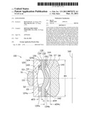
359715
Class name: Lens including a nonspherical surface having four components
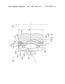
Publication date: 2011-03-31
Patent application number: 20110075272
rom the object, includes positive first lens,
negative second lens, positive third lens, positive fourth lens, and an
aperture stop positioned between the third and fourth lens. The second
lens includes a first optical portion, a first support portion
surrounding the first optical portion with a first surface and second
surface. The third lens includes a second optical portion and a second
support portion surrounding the second optical portion with a third
surface and fourth surface. The fourth lens includes a light stop surface
facing the object side of the lens system. The lens system satisfies the
formulas: d23<1.1×d34, where the d23 is a
distance along the optical axis of the lens system from the second
surface to the third surface, and the d34 is a distance along the
optical axis from the fourth surface to the light stop surface.Claims:
1. A lens system, in order from the object side to the image side,
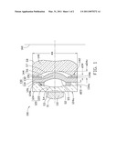
comprising a first lens with positive refractive power, a second lens
with negative refractive power, a third lens with positive refractive
power, a fourth lens with positive refractive power, and an aperture stop
positioned between the third lens and the fourth lens; wherein,the second
lens comprises a first optical portion, a first support portion
surrounding the first optical portion, the first support portion having a
first surface and an opposite second surface facing the image side, and a
flange protruding from the second surface and attached to the third
lens;the third lens comprises a second optical portion and a second
support portion surrounding the second optical portion; the second
support portion comprises a third surface and an opposite fourth surface
facing the image side;the fourth lens comprises a light stop surface
facing the object side, and an annular shim mounted on the light stop
surface of the fourth lens; andthe lens system satisfies the following
formula: d23<1.1.times.d34, where d23 is the distance
along the optical axis of the lens system from the second surface of the
second lens to the third surface of the third lens, and d34 is the
distance along the optical axis of the lens system from the fourth
surface to the light stop surface of the fourth lens.
2. The lens system as claimed in claim 1, wherein the lens system further satisfies the following formula: d34<0.1.times.φ4, where φ4 is the outer diameter of the fourth lens.
3. The lens system as claimed in claim 2, wherein the lens system further satisfies the following formula: d34<d34c, where d34c is the distance along the optical axis of the lens system from the center point of the object side lens surface of the fourth lens to the fourth surface of the third lens.
4. The lens system as claimed in claim 3, wherein all the first through fourth surfaces are aspheric surfaces.
5. The lens system as claimed in claim 4, wherein the first to fourth lenses are made of transparent resin.
6. The lens system as claimed in claim 4, wherein the first to fourth lens are made of glass material.
7. A lens system, in order from the object side to the image side, comprising a first lens with positive refractive power, a second lens with negative refractive power, a third lens with positive refractive power, and a fourth lens with negative refractive power, and an aperture stop positioned between the third lens and the fourth lens; wherein,the second lens comprises a first optical portion, a first support portion surrounding the first optical portion, the first support portion having a first surface and an opposite second surface facing the image side, and a flange protruding from the second surface and adhered to the third lens;the third lens comprises a second optical portion and a second support portion surrounding the second optical portion; the second support portion comprises a third surface and a fourth surface facing the image side;the fourth lens comprises a light stop surface facing the object side of the lens system, and an annular shim mounted on the light stop surface of the fourth lens;the lens system satisfies the following formula: d23<1.1.times.d34, where d23 is the distance along the optical axis of the lens system from the second surface of the second lens to the third surface of the third lens, and d34 is the distance along the optical axis of the lens system from the fourth surface to the light stop surface of the fourth lens.
8. The lens system as claimed in claim 6, wherein the lens system further satisfies the following formula: d34<0.1.times.φ4, where φ4 is the outer diameter of the fourth lens.
9. The lens system as claimed in claim 8, wherein lens system further satisfies the following formula: d34<d34c, where d34c is the distance along the optical axis of the lens system from the center point of the object side lens surface of the fourth lens to the fourth surface of the third lens.
10. The lens system as claimed in claim 9, wherein all the first through fourth surfaces are aspheric surfaces.
11. The lens system as claimed in claim 10, wherein the first to fourth lens are made of transparent resin.
12. The lens system as claimed in claim 10, wherein the first to fourth lens are made of glass material.Description:
BACKGROUND
[0001]1. Technical Field
[0002]The disclosure relates to lens systems.
[0003]2. Description of Related Art
[0004]In order to obtain high quality images, yet still offer small-sized camera modules for use in thin electronic devices, such as mobile phones, personal digital assistants (PDA), or webcams for personal computers, the camera modules must have a lens system with high resolution but short overall length (the distance from the object-side surface of the imaging lens to the imaging plane of the camera module). Therefore, lenses of imaging lenses system are generally designed to provide at least one large curvature lens surface to correct aberration and increase resolution. However, large curvature lens surfaces increase the intervals between adjacent lenses and harmful stray light may enter the lens system, which has various undesirable effects on the performance of the lens system.
[0005]Therefore it is desirable to provide a lens system, which can overcome the above problems.
BRIEF DESCRIPTION OF THE DRAWINGS
[0006]FIG. 1 is a schematic view of a lens system in accordance with an embodiment.
[0007]FIG. 2 is similar to FIG. 1, but showing a light path of a stray light beam transmitting in the lens system of FIG. 1.
DETAILED DESCRIPTION
[0008]Referring to FIG. 1, a lens system 100 according to one exemplary embodiment, in order from the object side to the image side thereof, includes a first lens 110 with positive refractive power, a second lens 120 with negative refractive power, a third lens 130 with positive refractive power, and a fourth lens 140 with either positive or negative refractive power. Each of the first through fourth lenses 110˜140 includes two lens surfaces at the image side and object side to converge or diverge transmitted light.
[0009]The first lens 110 is a biconvex lens and includes a first lens surface 51 and a second lens surface S2 in order from the object side to the image side.
[0010]The second lens 120 is a biconcave lens and includes a third lens surface S3 and a fourth lens surface S4 in order from the object side to the image side. The second lens 120 includes a first optical portion 122 and a first support portion 124 surrounding the first optical portion 122. The first support portion 124 includes a first surface 124a and an opposite second surface 124b facing the image side. A flange 126 protrudes from the second surface 124b towards the image side of the lens system 100, attached with the third lens 130.
[0011]The third lens 130 is a meniscus lens and includes a fifth lens surface S5 and a sixth lens surface S6 in order from the object side to the image side. The third lens 130 includes a second optical portion 132 and a second support portion 134 surrounding the second optical portion 132. The second support portion 134 includes a third surface 134a and an opposite fourth surface 134b facing the image side.
[0012]The fourth lens 140 is a biconcave lens and includes a seventh lens surface S7 and an eighth lens surface S8 in order from the object side to the image side. The fourth lens 140 further includes a light stop surface 142 facing the object side of the lens system 100 and surrounding the seventh lens surface S7, and an annular shim 144 is mounted on the stop surface 142. All of the lens surfaces S1 to S8 are aspheric.
[0013]In the present disclosure, the first to fourth lens 110˜140 can be made of glass material to eliminate aberrations and enhance the performance of the lens system, or of transparent resin to reduce the cost of the lens system.
[0014]The lens system 100 further includes an aperture stop 150 and an image sensor 160. The aperture stop 150 is positioned between, and adhered to the third lens 130 and the fourth lens 140. The image sensor 160 is positioned at the imaging plane of the lens system 100 for receiving the optical image formed by the lens system 100 and photo-electrically converting the optical image into image signals.
[0015]In order to shorten the overall length of the lens system 100 and prevent stray light entering the lens system 100, the lens system 100 satisfies the following formula (a): d23<1.1×d34; where d23 is the distance along the optical axis of the lens system 100 from the second surface 124b of the second lens 120 to the third surface 134a of the third lens 130, and d34 is the distance along the optical axis of the lens system 100 from the fourth surface 134b to the light stop surface 142 of the fourth lens 140.
[0016]The formulas (a) ensures the distance between the third lens 130 and the fourth lens 140 along the optical axis of the lens system 100 is big enough for accommodating the large curvature lens surface of the third lens 130, while reducing the distance between the second lens 120 and the third lens 130 to reduce the overall length of the lens system 100. In addition, the aperture stop 150 disposed between the fourth lens 140 and the third lens 130 can effectively prevent stray light from entering the fourth lens 140.
[0017]Alternatively, the lens system 100 may further satisfy the following formula (b): d34<0.1×φ4, where φ4 is the outer diameter of the fourth lens 110. Formula (b) ensures the lens system 100 to be compact.
[0018]Alternatively, the lens system 100 may yet further satisfy the following formula (c): d34<d34c, where d34c is the distance along the optical axis of the lens system 110 from the center point of the seventh lens surface S7 of the fourth lens 140 to the fourth surface 134b of the third lens 130.
[0019]The formula (c) ensures the distance between the third lens 130 and the fourth lens 140 along the optical axis of the lens system 100 is big enough for accommodating the large curvature lens surface of the third 130, thereby further reducing the overall length of the lens system 100.
[0020]Detailed examples of the lens system 100 are given below, but it should be noted that the lens system 100 is not limited to those examples. Listed below are the symbols used in detailed examples:
[0021]R: radius of curvature;
[0022]D: distance between two adjacent lens surfaces along the optical axis of the lens system 100; and
[0023]C: conical coefficient of each lens surface;
[0024]Tables 1, 2 show the lens data of an exemplary embodiment, where the pupil radius of the lens system 100 is 2.0 mm, and the overall length of the lens system 100 is 2.4 cm.
TABLE-US-00001 TABLE 1 Lens surface R(mm) D(mm) C S1 1.186431 0.5124478 -0.4817564 S2 -5.73043 0.1 -300 S3 -2.323946 0.32 0.7955866 S4 -36.35742 0.5910152 0 S5 -1.140924 0.4629918 0.0404088 S6 -0.8310764 0.1 -2.806995 S7 -7.600847 0.7363099 0 S8 1.681165 0.206 -16.56742
[0025]Table 2 lists the aspheric coefficients of the lens surfaces of each lens 110˜140.
TABLE-US-00002 TABLE 2 Lens surface K A B C D E S1 -0.4817564 0.027809547 0.25751331 -2.12575 6.7098661 -7.6183648 S2 -300 0.01379851 -0.052779569 1.3862868 -7.7951195 7.4200103 S3 0.7955866 0.49432381 -0.56598918 -0.024791235 -0.94493108 0 S4 0 0.41970372 -0.15139158 -0.37788836 0.78115421 0 S5 0.0404088 0.25898809 -1.1100482 3.0462237 -3.4648943 1.7720142 S6 -2.806995 -0.24913678 -0.034063924 0.34831869 -0.0076445571 -0.046207963 S7 0 -0.31540436 0.19175193 0.069164591 -0.15858844 0.059765584 S8 -16.56742 -0.14300961 0.072084823 -0.032492137 0.0082054096 -0.0010787984
The aspherical surface is shaped according to the formula:
z = ch 2 1 + 1 - ( k + 1 ) c 2 h 2 + Ah 4 + Bh 6 + Ch 8 + Dh 10 + Eh 12 , ##EQU00001##
wherein a light travelling direction along an optical axis is taken as z, a direction perpendicular to the optical is taken as h, c represents a paraxial radius of curvature, k represents a conical coefficient constant, and A to E denote i-th order correction coefficients of the aspheric surfaces.
[0026]In use, referring to FIG. 2, a stray light L is generated at the second lens surface S4 of the second lens 120, and projects to the first surface 124a of the second lens 120. Then, the stray light L is reflected by the first surface 124a of the second lens 120 and a side surface of the second lens 120, and projects towards the fourth lens 140 through the third lens 130. The stray light L is finally stopped by the light stop 150 situated in the way of the stray light L, thereby preventing the stray light L from entering the fourth lens 140 and effecting on image sensor 160.
[0027]It is believed that the present embodiments and their advantages will be understood from the foregoing description, and it will be apparent that various changes may be made thereto without departing from the spirit and scope of the disclosure or sacrificing all of its material advantages, the examples hereinbefore described merely being preferred or exemplary embodiments of the disclosure.
Claims:
1. A lens system, in order from the object side to the image side,
comprising a first lens with positive refractive power, a second lens
with negative refractive power, a third lens with positive refractive
power, a fourth lens with positive refractive power, and an aperture stop
positioned between the third lens and the fourth lens; wherein,the second
lens comprises a first optical portion, a first support portion
surrounding the first optical portion, the first support portion having a
first surface and an opposite second surface facing the image side, and a
flange protruding from the second surface and attached to the third
lens;the third lens comprises a second optical portion and a second
support portion surrounding the second optical portion; the second
support portion comprises a third surface and an opposite fourth surface
facing the image side;the fourth lens comprises a light stop surface
facing the object side, and an annular shim mounted on the light stop
surface of the fourth lens; andthe lens system satisfies the following
formula: d23<1.1.times.d34, where d23 is the distance
along the optical axis of the lens system from the second surface of the
second lens to the third surface of the third lens, and d34 is the
distance along the optical axis of the lens system from the fourth
surface to the light stop surface of the fourth lens.
2. The lens system as claimed in claim 1, wherein the lens system further satisfies the following formula: d34<0.1.times.φ4, where φ4 is the outer diameter of the fourth lens.
3. The lens system as claimed in claim 2, wherein the lens system further satisfies the following formula: d34<d34c, where d34c is the distance along the optical axis of the lens system from the center point of the object side lens surface of the fourth lens to the fourth surface of the third lens.
4. The lens system as claimed in claim 3, wherein all the first through fourth surfaces are aspheric surfaces.
5. The lens system as claimed in claim 4, wherein the first to fourth lenses are made of transparent resin.
6. The lens system as claimed in claim 4, wherein the first to fourth lens are made of glass material.
7. A lens system, in order from the object side to the image side, comprising a first lens with positive refractive power, a second lens with negative refractive power, a third lens with positive refractive power, and a fourth lens with negative refractive power, and an aperture stop positioned between the third lens and the fourth lens; wherein,the second lens comprises a first optical portion, a first support portion surrounding the first optical portion, the first support portion having a first surface and an opposite second surface facing the image side, and a flange protruding from the second surface and adhered to the third lens;the third lens comprises a second optical portion and a second support portion surrounding the second optical portion; the second support portion comprises a third surface and a fourth surface facing the image side;the fourth lens comprises a light stop surface facing the object side of the lens system, and an annular shim mounted on the light stop surface of the fourth lens;the lens system satisfies the following formula: d23<1.1.times.d34, where d23 is the distance along the optical axis of the lens system from the second surface of the second lens to the third surface of the third lens, and d34 is the distance along the optical axis of the lens system from the fourth surface to the light stop surface of the fourth lens.
8. The lens system as claimed in claim 6, wherein the lens system further satisfies the following formula: d34<0.1.times.φ4, where φ4 is the outer diameter of the fourth lens.
9. The lens system as claimed in claim 8, wherein lens system further satisfies the following formula: d34<d34c, where d34c is the distance along the optical axis of the lens system from the center point of the object side lens surface of the fourth lens to the fourth surface of the third lens.
10. The lens system as claimed in claim 9, wherein all the first through fourth surfaces are aspheric surfaces.
11. The lens system as claimed in claim 10, wherein the first to fourth lens are made of transparent resin.
12. The lens system as claimed in claim 10, wherein the first to fourth lens are made of glass material.
Description:
BACKGROUND
[0001]1. Technical Field
[0002]The disclosure relates to lens systems.
[0003]2. Description of Related Art
[0004]In order to obtain high quality images, yet still offer small-sized camera modules for use in thin electronic devices, such as mobile phones, personal digital assistants (PDA), or webcams for personal computers, the camera modules must have a lens system with high resolution but short overall length (the distance from the object-side surface of the imaging lens to the imaging plane of the camera module). Therefore, lenses of imaging lenses system are generally designed to provide at least one large curvature lens surface to correct aberration and increase resolution. However, large curvature lens surfaces increase the intervals between adjacent lenses and harmful stray light may enter the lens system, which has various undesirable effects on the performance of the lens system.
[0005]Therefore it is desirable to provide a lens system, which can overcome the above problems.
BRIEF DESCRIPTION OF THE DRAWINGS
[0006]FIG. 1 is a schematic view of a lens system in accordance with an embodiment.
[0007]FIG. 2 is similar to FIG. 1, but showing a light path of a stray light beam transmitting in the lens system of FIG. 1.
DETAILED DESCRIPTION
[0008]Referring to FIG. 1, a lens system 100 according to one exemplary embodiment, in order from the object side to the image side thereof, includes a first lens 110 with positive refractive power, a second lens 120 with negative refractive power, a third lens 130 with positive refractive power, and a fourth lens 140 with either positive or negative refractive power. Each of the first through fourth lenses 110˜140 includes two lens surfaces at the image side and object side to converge or diverge transmitted light.
[0009]The first lens 110 is a biconvex lens and includes a first lens surface 51 and a second lens surface S2 in order from the object side to the image side.
[0010]The second lens 120 is a biconcave lens and includes a third lens surface S3 and a fourth lens surface S4 in order from the object side to the image side. The second lens 120 includes a first optical portion 122 and a first support portion 124 surrounding the first optical portion 122. The first support portion 124 includes a first surface 124a and an opposite second surface 124b facing the image side. A flange 126 protrudes from the second surface 124b towards the image side of the lens system 100, attached with the third lens 130.
[0011]The third lens 130 is a meniscus lens and includes a fifth lens surface S5 and a sixth lens surface S6 in order from the object side to the image side. The third lens 130 includes a second optical portion 132 and a second support portion 134 surrounding the second optical portion 132. The second support portion 134 includes a third surface 134a and an opposite fourth surface 134b facing the image side.
[0012]The fourth lens 140 is a biconcave lens and includes a seventh lens surface S7 and an eighth lens surface S8 in order from the object side to the image side. The fourth lens 140 further includes a light stop surface 142 facing the object side of the lens system 100 and surrounding the seventh lens surface S7, and an annular shim 144 is mounted on the stop surface 142. All of the lens surfaces S1 to S8 are aspheric.
[0013]In the present disclosure, the first to fourth lens 110˜140 can be made of glass material to eliminate aberrations and enhance the performance of the lens system, or of transparent resin to reduce the cost of the lens system.
[0014]The lens system 100 further includes an aperture stop 150 and an image sensor 160. The aperture stop 150 is positioned between, and adhered to the third lens 130 and the fourth lens 140. The image sensor 160 is positioned at the imaging plane of the lens system 100 for receiving the optical image formed by the lens system 100 and photo-electrically converting the optical image into image signals.
[0015]In order to shorten the overall length of the lens system 100 and prevent stray light entering the lens system 100, the lens system 100 satisfies the following formula (a): d23<1.1×d34; where d23 is the distance along the optical axis of the lens system 100 from the second surface 124b of the second lens 120 to the third surface 134a of the third lens 130, and d34 is the distance along the optical axis of the lens system 100 from the fourth surface 134b to the light stop surface 142 of the fourth lens 140.
[0016]The formulas (a) ensures the distance between the third lens 130 and the fourth lens 140 along the optical axis of the lens system 100 is big enough for accommodating the large curvature lens surface of the third lens 130, while reducing the distance between the second lens 120 and the third lens 130 to reduce the overall length of the lens system 100. In addition, the aperture stop 150 disposed between the fourth lens 140 and the third lens 130 can effectively prevent stray light from entering the fourth lens 140.
[0017]Alternatively, the lens system 100 may further satisfy the following formula (b): d34<0.1×φ4, where φ4 is the outer diameter of the fourth lens 110. Formula (b) ensures the lens system 100 to be compact.
[0018]Alternatively, the lens system 100 may yet further satisfy the following formula (c): d34<d34c, where d34c is the distance along the optical axis of the lens system 110 from the center point of the seventh lens surface S7 of the fourth lens 140 to the fourth surface 134b of the third lens 130.
[0019]The formula (c) ensures the distance between the third lens 130 and the fourth lens 140 along the optical axis of the lens system 100 is big enough for accommodating the large curvature lens surface of the third 130, thereby further reducing the overall length of the lens system 100.
[0020]Detailed examples of the lens system 100 are given below, but it should be noted that the lens system 100 is not limited to those examples. Listed below are the symbols used in detailed examples:
[0021]R: radius of curvature;
[0022]D: distance between two adjacent lens surfaces along the optical axis of the lens system 100; and
[0023]C: conical coefficient of each lens surface;
[0024]Tables 1, 2 show the lens data of an exemplary embodiment, where the pupil radius of the lens system 100 is 2.0 mm, and the overall length of the lens system 100 is 2.4 cm.
TABLE-US-00001 TABLE 1 Lens surface R(mm) D(mm) C S1 1.186431 0.5124478 -0.4817564 S2 -5.73043 0.1 -300 S3 -2.323946 0.32 0.7955866 S4 -36.35742 0.5910152 0 S5 -1.140924 0.4629918 0.0404088 S6 -0.8310764 0.1 -2.806995 S7 -7.600847 0.7363099 0 S8 1.681165 0.206 -16.56742
[0025]Table 2 lists the aspheric coefficients of the lens surfaces of each lens 110˜140.
TABLE-US-00002 TABLE 2 Lens surface K A B C D E S1 -0.4817564 0.027809547 0.25751331 -2.12575 6.7098661 -7.6183648 S2 -300 0.01379851 -0.052779569 1.3862868 -7.7951195 7.4200103 S3 0.7955866 0.49432381 -0.56598918 -0.024791235 -0.94493108 0 S4 0 0.41970372 -0.15139158 -0.37788836 0.78115421 0 S5 0.0404088 0.25898809 -1.1100482 3.0462237 -3.4648943 1.7720142 S6 -2.806995 -0.24913678 -0.034063924 0.34831869 -0.0076445571 -0.046207963 S7 0 -0.31540436 0.19175193 0.069164591 -0.15858844 0.059765584 S8 -16.56742 -0.14300961 0.072084823 -0.032492137 0.0082054096 -0.0010787984
The aspherical surface is shaped according to the formula:
z = ch 2 1 + 1 - ( k + 1 ) c 2 h 2 + Ah 4 + Bh 6 + Ch 8 + Dh 10 + Eh 12 , ##EQU00001##
wherein a light travelling direction along an optical axis is taken as z, a direction perpendicular to the optical is taken as h, c represents a paraxial radius of curvature, k represents a conical coefficient constant, and A to E denote i-th order correction coefficients of the aspheric surfaces.
[0026]In use, referring to FIG. 2, a stray light L is generated at the second lens surface S4 of the second lens 120, and projects to the first surface 124a of the second lens 120. Then, the stray light L is reflected by the first surface 124a of the second lens 120 and a side surface of the second lens 120, and projects towards the fourth lens 140 through the third lens 130. The stray light L is finally stopped by the light stop 150 situated in the way of the stray light L, thereby preventing the stray light L from entering the fourth lens 140 and effecting on image sensor 160.
[0027]It is believed that the present embodiments and their advantages will be understood from the foregoing description, and it will be apparent that various changes may be made thereto without departing from the spirit and scope of the disclosure or sacrificing all of its material advantages, the examples hereinbefore described merely being preferred or exemplary embodiments of the disclosure.
User Contributions:
Comment about this patent or add new information about this topic:
Images included with this patent application:
 |  |
 |
| New patent applications in this class: | |
| Date | Title |
|---|---|
| 2018-01-25 | Optical image capturing system |
| 2018-01-25 | Optical image capturing system |
| 2018-01-25 | Wide-angle imaging lens module |
| 2016-06-30 | Imaging lens having four lens elements, and electronic apparatus having the same |
| 2016-06-23 | Image pickup lens, and camera module and digital device including the same |
| New patent applications from these inventors: | |
| Date | Title |
|---|---|
| 2011-09-29 | Light concentration device and related backlight module |
| 2011-06-09 | Touch panel input stylus |
| 2011-04-21 | Light pen |
| 2010-12-02 | Apparatus and method for detecting movement direction of object |
| 2010-12-02 | Image sensor, apparatus and method for detecting movement direction of object |
| Top Inventors for class "Optical: systems and elements" | |
| Rank | Inventor's name |
|---|---|
| 1 | Tsung Han Tsai |
| 2 | Hsin Hsuan Huang |
| 3 | Michio Cho |
| 4 | Niall R. Lynam |
| 5 | Tsung-Han Tsai |