Patent application title: Safety Needle Assembly
Inventors:
Christopher Mcdown (San Antonio, TX, US)
Eliot Zaiken (Covington, GA)
Tieming Ruan (Randolph, CN)
IPC8 Class: AA61M532FI
USPC Class:
604192
Class name: Means moved by person to inject or remove fluent material to or from body inserted conduit, holder, or reservoir injector or aspirator syringe supported only by person during use (e.g., hand held hypodermic syringe, douche tube with forced injection, etc.) having cover or protector for body entering conduit
Publication date: 2011-03-17
Patent application number: 20110066114
for an injector is provided herein which, in a
first aspect of the subject invention, includes a needle having a distal
end formed for injection, a carrier for supporting the needle, and a
shield for selectively covering the distal end of the needle. The shield
includes at least one through aperture formed therein, wherein the
through aperture is superimposed over the distal end of the needle in an
initial state prior to injection. In a further aspect of the subject
invention, a safety needle assembly is provided which includes a needle
having a distal end formed for injection, a earner for supporting the
needle, and a shield for selectively covering the distal end of the
needle. The shield includes a proximal and, a distal end and a sidewall
extending therebetween. The sidewall defines a first outer diameter at or
adjacent to the distal end, and the sidewall defines at least one outer
diameter greater than the first outer diameter at one or more locations
located proximally of the first outer diameter.Claims:
1. A safety needle assembly for an injector comprising:a needle having a
distal end formed for injection;a carrier for supporting said needle,
said carrier being configured or mounting onto an injector; and,a shield
for selectively covering the distal end of the needle, said shield having
at least one through aperture formed therein, wherein said through
aperture is superimposed over the distal end of the needle in an initial
state prior to injection as viewed along an axis disposed perpendicularly
to the needle.
2. An assembly as in claim 1, wherein said shield includes a distal end and a sidewall which extends proximally from said distal end, said through aperture is formed through said sidewall in proximity to said distal end.
3. An assembly as in claim 2, wherein said distal end spans across said through aperture.
4. An assembly as in claim 1, wherein a first edge of said through hole is located proximally of the distal end of the needle in the initial state prior to injection, said first edge being located distally of the distal end of the needle in a post-use state after injection.
5. An assembly as in claim 1, wherein at least two of said through apertures are provided.
6. An assembly as in claim 1, wherein said shield is movable relative to said carrier, said shield being movable to selectively expose and cover the distal end of the needle.
7. A safety needle assembly for an injector comprising:a needle having a distal end formed for injection;a carrier for supporting said needle, said carrier being configured for mounting onto an injector; and,a shield for selectively covering the distal end of the needle, said shield having a proximal end, a distal end and a sidewall extending therebetween, said sidewall defining a first outer diameter at or adjacent to said distal end, said sidewall defining at least one outer diameter greater than said first outer diameter at one or more locations located proximally of said first outer diameter.
8. An assembly as in claim 7, wherein said sidewall has a concave configuration proximally of said first outer diameter.
9. An assembly as in claim 7, wherein said sidewall has a tapered configuration proximally of said first outer diameter.
10. An assembly as in claim 7, wherein said sidewall includes a step change in diameter proximally of said first outer diameter.
11. An assembly as in claim 7, wherein said sidewall defines a greatest outer diameter at a location closer to said proximal end of said shield than said distal end of said shield.
12. An assembly as in claim 11, wherein said outer diameter of said shield gradually increases from said first outer diameter to said greatest outer diameter.
13. An assembly as in claim 11, wherein said outer shield defines said greatest outer diameter over a length of said shield extending from said proximal end.Description:
FIELD OF THE INVENTION
[0001]This invention relates to needle assemblies for injectors and, more particularly, to safety needle assemblies.
[0002]Safety needle assemblies are known in the prior art including safety pen needle assemblies for use with pen injectors. The assemblies are typically individually mountable to an injector. After injection, the assembly is configured to shield the used needle to prevent a user from inadvertently receiving a "needle stick". Typically, the assembly is formed to be removable from the injector and disposed after use.
[0003]Pen needles are of limited length, and prior art safety pen assembly designs have been found obtrusive in limiting visibility of placement of the pen needle against a patient's skin in performing an injection. In addition, a pen needle must be primed prior to use. Medication expelled during the priming procedure has been found to collect within a safety pen needle assembly. During injection, the expelled medication may be undesirably transferred to a patient's skin thereby causing confusion as to whether a dose was properly administered.
SUMMARY OF THE INVENTION
[0004]A safety needle assembly for an injector is provided herein which, in a first aspect of the subject invention, includes a needle having a distal end formed for injection, and a carrier for supporting the needle, the carrier being configured for mounting onto an injector. The assembly further includes a shield for selectively covering the distal end of the needle. The shield includes at least one through aperture formed therein, wherein the through aperture is superimposed over the distal end of the needle in an initial state prior to injection. Advantageously, during priming, the through aperture allows medication to pass therethrough, thereby minimizing the amount of expelled medication collected within the safety needle assembly.
[0005]In a further aspect of the subject invention, a safety needle assembly for an injector is provided which includes a needle having a distal end formed for injection, a carrier for supporting the needle, the carrier being configured for mounting onto an injector, and a shield for selectively covering the distal end of the needle. The shield includes a proximal and, a distal end and a sidewall extending therebetween. The sidewall defines a first outer diameter at or adjacent to the distal end, and the sidewall defines at least one outer diameter greater than the first outer diameter at one or more locations located proximally of the first outer diameter. Advantageously, with this arrangement, a shield may be provided which is less obtrusive to a user during injection, particularly in observing the point of injection.
[0006]As will be appreciated by those skilled in the art, the two aspects discussed above may be used in combination or separately.
[0007]These and other features of the invention will be better understood through a study of the following detailed description and accompanying drawings.
BRIEF DESCRIPTION OF THE DRAWINGS
[0008]FIGS. 1-7 show different depictions of a through aperture formed in accordance with the subject invention; and,
[0009]FIGS. 8-11 show different configurations of a shield having a reduced outer diameter in accordance with the subject invention.
DETAILED DESCRIPTION OF THE INVENTION
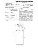
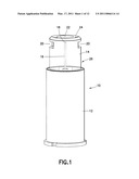
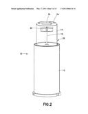
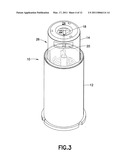
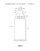
[0010]With reference to the figures, a safety needle assembly 10 is shown which generally includes a carrier or hub 12, a shield 14, and a needle 16. Various configurations of the carrier 12, the shield 14 and the needle 16 may be utilized consistent with the invention described herein. The needle 16 may be rigidly fixed to the carrier 12 or otherwise supported by the carrier 12 directly or through one or more intermediate components. The carrier 12 may also have features 15 provided which allow for mounting onto an injector P, such as threads, a luer-type connector or combinations thereof. Alternatively, the carrier 12 may be integrally formed or rigidly secured to the injector P. The injector P may be a pen injector or a syringe.
[0011]The needle 16 may be of any known design, including being a pen needle. Typically, pen needles have a gauge in the range of 29-33 gauge. The needle 16 terminates at a distal end 18, which is configured for injection into a patient. As is known in the art, the needle 16 may have a second, proximal end 17 formed to communicate with contents of the injector P. For example, the second, proximal end 17 may be formed for piercing through a septum of a drug cartridge contained in the injector P in accessing the medical contents therein for injection.
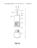
[0012]The shield 14 is formed to selectively cover the distal end 18 of the needle 16, particularly after use. It is preferred that the shield 14 cover the distal end 18 prior to use. As such, during use, the shield 14 must be allowed to retract and expose the distal end 18 for injection (as shown by the shield 14 in dashed lines in FIG. 1A). After use, the shield 14 must be driven forwardly to the covered, shielded position and, preferably, locked in the post-use position. Any known arrangement for allowing the shield 14 to be driven rearwardly (proximally) and then forwardly (distally) to a locked position may be used. The shield 14 may move relative to the carrier 12, which is fixed to the injector P. Automated systems ("passive" systems) or systems requiring manual intervention ("active" systems) may be utilized to move the shield 14. As used herein, the term "proximal" shall refer to the direction away from the patient (i.e., non-injection end), while, "distal" shall refer to the direction towards the patient (i.e., injection end).
[0013]Safety needle assemblies are known in the art having shields which retract for use from an initial covering position and cover the needle after use (i.e., the shield covers the distal end of the needle before and after use). Examples of such assemblies are found in U.S. Pat. No. 5,389,085; U.S. Pat. No. 6,203,529; U.S. Pat. No. 6,547,764; U.S. Pat. No. 6,986,760; and U.S. Published Patent Application. No. 2005/0038392, which are incorporated by reference herein. These shielding arrangements may be utilized with the subject invention.
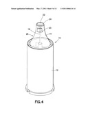
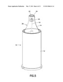
[0014]As shown in FIGS. 1-7, in a first aspect of the subject invention, at least one through aperture 20 is formed in the shield 14. As best shown in FIG. 6, in an initial state of the safety needle assembly 10 prior to use, it is preferred that the through aperture 20 be superimposed over the distal end 18 of the needle 16 as viewed along an axis disposed perpendicularly to the needle 16. In this manner, the distal end 18 of the needle 16 is viewable within the footprint of the through aperture 20 as viewed along an axis disposed perpendicularly to the needle 16. With this arrangement, the needle 16 may be primed prior to injection, with medication being expelled from the needle 16 during priming being allowed to escape through the through aperture 20. An opening 22 may be formed in a distal end 24 of the shield 14 to also allow expelled medication to be discharged out of the safety needle assembly 10 during priming. During use, the needle 16 may extend through the opening 22 to allow injection of the distal end 18 into a patient.
[0015]For convenience of the user, it is preferred that at least two of the through apertures 20 be provided, which are located diametrically opposite along the circumference of the shield 14. It is preferred that during priming, the needle 16 be oriented horizontally or downwardly so that expelled medication has a greater chance of being discharged through at least one of the through apertures 20.
[0016]The shield 14 includes a sidewall 26 which extends proximally from the distal end 24. It is preferred that the through aperture 20 be formed through the sidewall 26 adjacent to or in proximity to the distal end 24. Preferably, the distal end 24 has portions which uninterruptedly span across the through aperture 20. This arrangement provides rigidity at the distal end 24 which offsets at least some loss of rigidity due to the presence of one or more of the through apertures 20. As shown in the figures, the sidewall may be formed with various configurations, e.g., cylindrical, tapered, and so forth.
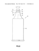
[0017]The through apertures 20 may be formed with different sizes and configurations. With reference to FIG. 6, it is noted that the width L of through aperture 20 should be limited, since an excessively great width will result in excessive weakening of the shield 14. The width L may be in the range of 20%-90% of the circumference of the shield 14 taken at the location of the through aperture 20.
[0018]It is preferred that the through aperture 20 have a rectangular configuration with a lower edge 28 being located a distance H from the distal end 18. With reference to FIGS. 6 and 7, the lower edge 28 is preferably located to be proximal of the distal end 18 in an initial state of the safety pen needle assembly 10 prior to use (FIG. 6) and located distally of the distal end 18 after use (e.g., with the shield 14 being in a locked shielded state) (FIG. 7). Thus, the through aperture 20 is located more distally from the carrier 12 after use, then before use. A user may observe the location of the lower edge 28 relative to the distal end 18 and readily determine if there has been use of the safety pen needle assembly 10. The lower edge 28 thus acts as an indicator for indicating usage of the safety needle assembly 10. This is particularly helpful for a safety needle assembly which shields the needle 16 prior to use. As further indication of usage, an insignia (e.g., logo) or other visible feature 30 may be provided on the shield 14 which is covered by the carrier 12 in an initial state (FIG. 6) and exposed in a shielded state (FIG. 7).
[0019]As will be appreciated by those skilled in the art, the through aperture 20 permits a user to view the distal end 18 of the needle 16 during priming, even with the shield 14 being formed of opaque material. The through aperture 20 also permits a user to visually confirm the geometry of the needle 16.
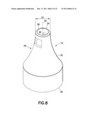
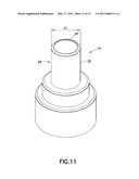
[0020]With reference to FIGS. 8-11, in a second aspect of the subject invention, the shield 14 may be formed such that the sidewall 26, on an outer surface 32 thereof, has a reduced outer diameter D1 at or adjacent to the distal end 24 as compared to proximally-located portions of the shield 14. The sidewall 26 extends between the distal end 18 and a proximal end 36 of the shield 14 with the outer surface 32 facing away from a longitudinal axis 34 of the shield 14. The distal end 24 and the proximal end 36 are disposed to face generally, distally and proximally, respectively, along the longitudinal axis 34.
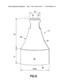
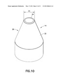
[0021]With the subject invention, at least one outer diameter is defined on the outer surface 32 which is greater than the reduced outer diameter D1 at one or more locations located proximally of the reduced outer diameter D1. In this manner, a change in outer diameter is provided on the shield 14 from the distal end 18 proceeding proximally along the shield 14. As shown in FIGS. 8 and 9, the change may be gradual so as to impart a concave configuration to the sidewall 26. Alternatively, the sidewall 26 may have a tapered configuration, as shown in FIG. 10 or a step change, as shown in FIG. 11. Other configurations for the sidewall 26 are possible, which may include arcuate, linear, and/or irregular segments. The concave configuration of the sidewall 26 shown in FIGS. 8 and 9 is preferred.
[0022]It is preferred that the outer diameter of the shield 14 be greatest (Dmax) at a location closer to the proximal end 36 of the shield 14 than the distal end 18 of the shield 14. The shield 14 may define a constant section having the greatest outer diameter Dmax, such that a cylinder 33 is defined having the greatest outer diameter Dmax. The cylinder 33 may extend from the proximal end 36 of the shield 14, It is further preferred that the outer diameter of the shield 14 gradually increase from the reduced outer diameter D1 to the greatest outer diameter Dmax.
[0023]In a preferred arrangement, the distalmost location of the greatest outer diameter Dmax is located at a distance T1 from the proximal end 36 of the shield 14 and a distance T2 from the distal end 18 of the shield 14, where T2>T1.
[0024]With the reduced outer diameter D1 at the distal end 24, the shield 14 may provide the safety needle assembly 10 with a more aesthetically-pleasing appearance, In addition, the distal end may provide a guide for orienting the safety pen needle assembly 10 during an injection.
[0025]It is preferred that the distal end 24 be formed with minimal surface area, to limit skin contact area. The distal end 24 may be annular (circumscribing the opening 22) having a width generally equal to the thickness of the sidewall 26. Preferably, the sidewall 26 defines an inner diameter in the range of 0.110-0.325 inches adjacent to the distal end 24 (this inner diameter may be equal to the diameter of the opening 22). To provide added comfort for a patient, a rounded fillet 38 may be provided on the distal end 24 for engagement against a patient's skin. The rounded configuration provides a more comfortable engagement surface during injection.
[0026]As will be appreciated by those skilled in the art, the two aspects discussed above may be used in combination or separately.
Claims:
1. A safety needle assembly for an injector comprising:a needle having a
distal end formed for injection;a carrier for supporting said needle,
said carrier being configured or mounting onto an injector; and,a shield
for selectively covering the distal end of the needle, said shield having
at least one through aperture formed therein, wherein said through
aperture is superimposed over the distal end of the needle in an initial
state prior to injection as viewed along an axis disposed perpendicularly
to the needle.
2. An assembly as in claim 1, wherein said shield includes a distal end and a sidewall which extends proximally from said distal end, said through aperture is formed through said sidewall in proximity to said distal end.
3. An assembly as in claim 2, wherein said distal end spans across said through aperture.
4. An assembly as in claim 1, wherein a first edge of said through hole is located proximally of the distal end of the needle in the initial state prior to injection, said first edge being located distally of the distal end of the needle in a post-use state after injection.
5. An assembly as in claim 1, wherein at least two of said through apertures are provided.
6. An assembly as in claim 1, wherein said shield is movable relative to said carrier, said shield being movable to selectively expose and cover the distal end of the needle.
7. A safety needle assembly for an injector comprising:a needle having a distal end formed for injection;a carrier for supporting said needle, said carrier being configured for mounting onto an injector; and,a shield for selectively covering the distal end of the needle, said shield having a proximal end, a distal end and a sidewall extending therebetween, said sidewall defining a first outer diameter at or adjacent to said distal end, said sidewall defining at least one outer diameter greater than said first outer diameter at one or more locations located proximally of said first outer diameter.
8. An assembly as in claim 7, wherein said sidewall has a concave configuration proximally of said first outer diameter.
9. An assembly as in claim 7, wherein said sidewall has a tapered configuration proximally of said first outer diameter.
10. An assembly as in claim 7, wherein said sidewall includes a step change in diameter proximally of said first outer diameter.
11. An assembly as in claim 7, wherein said sidewall defines a greatest outer diameter at a location closer to said proximal end of said shield than said distal end of said shield.
12. An assembly as in claim 11, wherein said outer diameter of said shield gradually increases from said first outer diameter to said greatest outer diameter.
13. An assembly as in claim 11, wherein said outer shield defines said greatest outer diameter over a length of said shield extending from said proximal end.
Description:
FIELD OF THE INVENTION
[0001]This invention relates to needle assemblies for injectors and, more particularly, to safety needle assemblies.
[0002]Safety needle assemblies are known in the prior art including safety pen needle assemblies for use with pen injectors. The assemblies are typically individually mountable to an injector. After injection, the assembly is configured to shield the used needle to prevent a user from inadvertently receiving a "needle stick". Typically, the assembly is formed to be removable from the injector and disposed after use.
[0003]Pen needles are of limited length, and prior art safety pen assembly designs have been found obtrusive in limiting visibility of placement of the pen needle against a patient's skin in performing an injection. In addition, a pen needle must be primed prior to use. Medication expelled during the priming procedure has been found to collect within a safety pen needle assembly. During injection, the expelled medication may be undesirably transferred to a patient's skin thereby causing confusion as to whether a dose was properly administered.
SUMMARY OF THE INVENTION
[0004]A safety needle assembly for an injector is provided herein which, in a first aspect of the subject invention, includes a needle having a distal end formed for injection, and a carrier for supporting the needle, the carrier being configured for mounting onto an injector. The assembly further includes a shield for selectively covering the distal end of the needle. The shield includes at least one through aperture formed therein, wherein the through aperture is superimposed over the distal end of the needle in an initial state prior to injection. Advantageously, during priming, the through aperture allows medication to pass therethrough, thereby minimizing the amount of expelled medication collected within the safety needle assembly.
[0005]In a further aspect of the subject invention, a safety needle assembly for an injector is provided which includes a needle having a distal end formed for injection, a carrier for supporting the needle, the carrier being configured for mounting onto an injector, and a shield for selectively covering the distal end of the needle. The shield includes a proximal and, a distal end and a sidewall extending therebetween. The sidewall defines a first outer diameter at or adjacent to the distal end, and the sidewall defines at least one outer diameter greater than the first outer diameter at one or more locations located proximally of the first outer diameter. Advantageously, with this arrangement, a shield may be provided which is less obtrusive to a user during injection, particularly in observing the point of injection.
[0006]As will be appreciated by those skilled in the art, the two aspects discussed above may be used in combination or separately.
[0007]These and other features of the invention will be better understood through a study of the following detailed description and accompanying drawings.
BRIEF DESCRIPTION OF THE DRAWINGS
[0008]FIGS. 1-7 show different depictions of a through aperture formed in accordance with the subject invention; and,
[0009]FIGS. 8-11 show different configurations of a shield having a reduced outer diameter in accordance with the subject invention.
DETAILED DESCRIPTION OF THE INVENTION
[0010]With reference to the figures, a safety needle assembly 10 is shown which generally includes a carrier or hub 12, a shield 14, and a needle 16. Various configurations of the carrier 12, the shield 14 and the needle 16 may be utilized consistent with the invention described herein. The needle 16 may be rigidly fixed to the carrier 12 or otherwise supported by the carrier 12 directly or through one or more intermediate components. The carrier 12 may also have features 15 provided which allow for mounting onto an injector P, such as threads, a luer-type connector or combinations thereof. Alternatively, the carrier 12 may be integrally formed or rigidly secured to the injector P. The injector P may be a pen injector or a syringe.
[0011]The needle 16 may be of any known design, including being a pen needle. Typically, pen needles have a gauge in the range of 29-33 gauge. The needle 16 terminates at a distal end 18, which is configured for injection into a patient. As is known in the art, the needle 16 may have a second, proximal end 17 formed to communicate with contents of the injector P. For example, the second, proximal end 17 may be formed for piercing through a septum of a drug cartridge contained in the injector P in accessing the medical contents therein for injection.
[0012]The shield 14 is formed to selectively cover the distal end 18 of the needle 16, particularly after use. It is preferred that the shield 14 cover the distal end 18 prior to use. As such, during use, the shield 14 must be allowed to retract and expose the distal end 18 for injection (as shown by the shield 14 in dashed lines in FIG. 1A). After use, the shield 14 must be driven forwardly to the covered, shielded position and, preferably, locked in the post-use position. Any known arrangement for allowing the shield 14 to be driven rearwardly (proximally) and then forwardly (distally) to a locked position may be used. The shield 14 may move relative to the carrier 12, which is fixed to the injector P. Automated systems ("passive" systems) or systems requiring manual intervention ("active" systems) may be utilized to move the shield 14. As used herein, the term "proximal" shall refer to the direction away from the patient (i.e., non-injection end), while, "distal" shall refer to the direction towards the patient (i.e., injection end).
[0013]Safety needle assemblies are known in the art having shields which retract for use from an initial covering position and cover the needle after use (i.e., the shield covers the distal end of the needle before and after use). Examples of such assemblies are found in U.S. Pat. No. 5,389,085; U.S. Pat. No. 6,203,529; U.S. Pat. No. 6,547,764; U.S. Pat. No. 6,986,760; and U.S. Published Patent Application. No. 2005/0038392, which are incorporated by reference herein. These shielding arrangements may be utilized with the subject invention.
[0014]As shown in FIGS. 1-7, in a first aspect of the subject invention, at least one through aperture 20 is formed in the shield 14. As best shown in FIG. 6, in an initial state of the safety needle assembly 10 prior to use, it is preferred that the through aperture 20 be superimposed over the distal end 18 of the needle 16 as viewed along an axis disposed perpendicularly to the needle 16. In this manner, the distal end 18 of the needle 16 is viewable within the footprint of the through aperture 20 as viewed along an axis disposed perpendicularly to the needle 16. With this arrangement, the needle 16 may be primed prior to injection, with medication being expelled from the needle 16 during priming being allowed to escape through the through aperture 20. An opening 22 may be formed in a distal end 24 of the shield 14 to also allow expelled medication to be discharged out of the safety needle assembly 10 during priming. During use, the needle 16 may extend through the opening 22 to allow injection of the distal end 18 into a patient.
[0015]For convenience of the user, it is preferred that at least two of the through apertures 20 be provided, which are located diametrically opposite along the circumference of the shield 14. It is preferred that during priming, the needle 16 be oriented horizontally or downwardly so that expelled medication has a greater chance of being discharged through at least one of the through apertures 20.
[0016]The shield 14 includes a sidewall 26 which extends proximally from the distal end 24. It is preferred that the through aperture 20 be formed through the sidewall 26 adjacent to or in proximity to the distal end 24. Preferably, the distal end 24 has portions which uninterruptedly span across the through aperture 20. This arrangement provides rigidity at the distal end 24 which offsets at least some loss of rigidity due to the presence of one or more of the through apertures 20. As shown in the figures, the sidewall may be formed with various configurations, e.g., cylindrical, tapered, and so forth.
[0017]The through apertures 20 may be formed with different sizes and configurations. With reference to FIG. 6, it is noted that the width L of through aperture 20 should be limited, since an excessively great width will result in excessive weakening of the shield 14. The width L may be in the range of 20%-90% of the circumference of the shield 14 taken at the location of the through aperture 20.
[0018]It is preferred that the through aperture 20 have a rectangular configuration with a lower edge 28 being located a distance H from the distal end 18. With reference to FIGS. 6 and 7, the lower edge 28 is preferably located to be proximal of the distal end 18 in an initial state of the safety pen needle assembly 10 prior to use (FIG. 6) and located distally of the distal end 18 after use (e.g., with the shield 14 being in a locked shielded state) (FIG. 7). Thus, the through aperture 20 is located more distally from the carrier 12 after use, then before use. A user may observe the location of the lower edge 28 relative to the distal end 18 and readily determine if there has been use of the safety pen needle assembly 10. The lower edge 28 thus acts as an indicator for indicating usage of the safety needle assembly 10. This is particularly helpful for a safety needle assembly which shields the needle 16 prior to use. As further indication of usage, an insignia (e.g., logo) or other visible feature 30 may be provided on the shield 14 which is covered by the carrier 12 in an initial state (FIG. 6) and exposed in a shielded state (FIG. 7).
[0019]As will be appreciated by those skilled in the art, the through aperture 20 permits a user to view the distal end 18 of the needle 16 during priming, even with the shield 14 being formed of opaque material. The through aperture 20 also permits a user to visually confirm the geometry of the needle 16.
[0020]With reference to FIGS. 8-11, in a second aspect of the subject invention, the shield 14 may be formed such that the sidewall 26, on an outer surface 32 thereof, has a reduced outer diameter D1 at or adjacent to the distal end 24 as compared to proximally-located portions of the shield 14. The sidewall 26 extends between the distal end 18 and a proximal end 36 of the shield 14 with the outer surface 32 facing away from a longitudinal axis 34 of the shield 14. The distal end 24 and the proximal end 36 are disposed to face generally, distally and proximally, respectively, along the longitudinal axis 34.
[0021]With the subject invention, at least one outer diameter is defined on the outer surface 32 which is greater than the reduced outer diameter D1 at one or more locations located proximally of the reduced outer diameter D1. In this manner, a change in outer diameter is provided on the shield 14 from the distal end 18 proceeding proximally along the shield 14. As shown in FIGS. 8 and 9, the change may be gradual so as to impart a concave configuration to the sidewall 26. Alternatively, the sidewall 26 may have a tapered configuration, as shown in FIG. 10 or a step change, as shown in FIG. 11. Other configurations for the sidewall 26 are possible, which may include arcuate, linear, and/or irregular segments. The concave configuration of the sidewall 26 shown in FIGS. 8 and 9 is preferred.
[0022]It is preferred that the outer diameter of the shield 14 be greatest (Dmax) at a location closer to the proximal end 36 of the shield 14 than the distal end 18 of the shield 14. The shield 14 may define a constant section having the greatest outer diameter Dmax, such that a cylinder 33 is defined having the greatest outer diameter Dmax. The cylinder 33 may extend from the proximal end 36 of the shield 14, It is further preferred that the outer diameter of the shield 14 gradually increase from the reduced outer diameter D1 to the greatest outer diameter Dmax.
[0023]In a preferred arrangement, the distalmost location of the greatest outer diameter Dmax is located at a distance T1 from the proximal end 36 of the shield 14 and a distance T2 from the distal end 18 of the shield 14, where T2>T1.
[0024]With the reduced outer diameter D1 at the distal end 24, the shield 14 may provide the safety needle assembly 10 with a more aesthetically-pleasing appearance, In addition, the distal end may provide a guide for orienting the safety pen needle assembly 10 during an injection.
[0025]It is preferred that the distal end 24 be formed with minimal surface area, to limit skin contact area. The distal end 24 may be annular (circumscribing the opening 22) having a width generally equal to the thickness of the sidewall 26. Preferably, the sidewall 26 defines an inner diameter in the range of 0.110-0.325 inches adjacent to the distal end 24 (this inner diameter may be equal to the diameter of the opening 22). To provide added comfort for a patient, a rounded fillet 38 may be provided on the distal end 24 for engagement against a patient's skin. The rounded configuration provides a more comfortable engagement surface during injection.
[0026]As will be appreciated by those skilled in the art, the two aspects discussed above may be used in combination or separately.
User Contributions:
Comment about this patent or add new information about this topic:
Images included with this patent application:
 |  |
 |  |
 |  |
 |  |
 |  |
 |  |
 |
| Similar patent applications: | |
| Date | Title |
|---|---|
| 2009-06-18 | Safety needle assembly |
| 2010-03-11 | Safety needle assembly and methods |
| 2010-04-08 | Safety needle assembly |
| 2011-01-20 | Safety reset key and needle assembly |
| 2009-11-26 | Safety intravenous catheter assembly |
| New patent applications in this class: | |
| Date | Title |
|---|---|
| 2016-09-01 | Tip cap assembly for closing an injection system |
| 2016-07-14 | Cap for a drug delivery device |
| 2016-07-07 | Rapid, non-destructive, selective infrared spectrometry analysis of organic coatings on molded articles |
| 2016-07-07 | Delivery device |
| 2016-07-07 | Medicament delivery device |
| Top Inventors for class "Surgery" | |
| Rank | Inventor's name |
|---|---|
| 1 | Christopher Brian Locke |
| 2 | Roderick A. Hyde |
| 3 | Lowell L. Wood, Jr. |
| 4 | Timothy Mark Robinson |
| 5 | Donald Carroll Roe |