Patent application title: Axial-flow compressor with a flow pulse generator
Inventors:
Carsten Clemen (Mittenwalde, DE)
Assignees:
Rolls-Royce Deutschland Ltd & Co KG
IPC8 Class: AF01D2524FI
USPC Class:
4151821
Class name: Rotary kinetic fluid motors or pumps working fluid passage or distributing means associated with runner (e.g., casing, etc.)
Publication date: 2011-01-20
Patent application number: 20110014037
luding, within a compressor casing (4), at least
one rotor (2) of rotor blades (3) connected to a drive shaft (1) and a
stator (5) held on the casing inner wall and, associated to the rotor gap
(6) between the blade tips and the casing inner wall, a flow pulse
generator (7) for stabilizing the rotor gap flow, characterized in that
the flow pulse generator (7) includes pulse channels (7a) arranged on the
inner wall of the casing and extending upstream of the rotor (2) and
tapering in flow direction to accelerate the wall-near flow (9), with the
shape and size of the pulse channels (7a) being determined by
circumferentially spacedly disposed, successive separators (7b) attached
without gap on the compressor casing inner wall. The flow pulse generator
(7) so designed, which is easily manufacturable, improves the
stabilization of the rotor gap (6) flow, extends the operating range of
the compressor and increases the surge limit.Claims:
1. Axial-flow compressor including, within a compressor casing (4), at
least one rotor (2) of rotor blades (3) connected to a drive shaft (1)
and a stator (5) held on the casing inner wall and, associated to the
rotor gap (6) between the blade tips and the casing inner wail, a flow
pulse generator (7) for stabilizing the rotor gap flow, characterized in
that the flow pulse generator (7) includes pulse channels (7a) arranged
on the inner wall of the casing and extending upstream of the rotor (2)
and tapering in flow direction to accelerate the wall-near flow (9), with
the shape and size of the pulse channels (7a) being determined by
circumferentially spacedly disposed, successive separators (7b) attached
without gap on the casing inner wall.
2. Axial-flow compressor in accordance with claim 1, characterized in that the pulse channels (7a) are each confined by opposite sidewalls (11) of the separators (7b), that the sidewalls (11) have an aerodynamically favourable--straight and/or curved--contour, and that the upstream inflow geometry of the separators (7b) is also aerodynamically favourable.
3. Axial-flow compressor in accordance with claim 1, characterized in that the pulse channels (7a) feature a rectangular cross-section.
4. Axial-flow compressor in accordance with claim 1, characterized in that the inlet cross-sections of the pulse channels (7a) are approximately twice their exit cross-sections.
5. Axial-flow compressor in accordance with claim 1, characterized in that the separators (7b) are covered towards the casing interior by a thin partition (12) separating them from the main flow to the rotors (2).
6. Axial-flow compressor in accordance with claim 5, characterized in that the partition (12) extends axial-parallelly in flow direction or follows the contour of the wall of the compressor casing (4).
7. Axial-flow compressor in accordance with claim 1, characterized in that the pulse channels and separators have a radial height (H) which--at most--is twice the width (B) of the rotor gap (6).
8. Axial-flow compressor in accordance with claim 1, characterized in that the length (L) of the pulse channels and separators in axial direction is between 10 and 100% of the chord length (S) at the rotor blade tip.
9. Axial-flow compressor in accordance with claim 1, characterized in that the pulse channels and separators terminate at a distance (A) to the leading edge of the rotor blades (3) which is between 10 and 100% of the length of the chord (S) at the rotor blade tip.
10. Axial-flow compressor in accordance with claim 1, characterized in that two or more pulse channels (7a) are provided for each rotor blade passage (10) situated between two rotor blades (3).Description:
[0001]This invention relates to an axial-flow compressor including, within
a compressor casing, at least one rotor of rotor blades connected to a
drive shaft and a stator held on the casing inner wall and, associated to
the rotor gap between the blade tips and the casing inner wall, a flow
pulse generator for stabilizing the rotor gap flow.
[0002]On axial-flow compressors, flow instabilities limiting its operating range may occur in the area of the rotor gap between the rotor blade tips and the compressor casing under high load, for example during strong acceleration of aircraft powered by a gas-turbine engine. A flow pulse generated on the rotor gap enables the gap swirl, which is critical at high compressor load, to be stabilized and, consequently, the operating range of the compressor extended or, respectively, the operating stability thereof improved.
[0003]According to a known measure for actively influencing compressor stability, compressed fluid is tapped from the rearward stages of the compressor and re-introduced in the blade tip area of the forward rotors to increase the flow pulse on the gap and thereby actively influence the rotor gap flow and stabilize the gap swirl. However, this process is disadvantageous in that the re-introduction of hot fluid from the rearward section of the compressor increases the temperature of the fluid in the compressor and, consequently, decreases compressor efficiency.
[0004]Compressor stability is also passively influencable by indentations provided in the compressor casing above the blade tips. A flow circulation effected by the indentation conveys a certain amount of energy into the forward area of the rotor tip, so that the pulse of the rotor inflow is increased and thus the rotor gap flow and ultimately compressor operation are stabilized. Apart from the fact that re-circulation of a certain fluid quantity also in this process entails an increase in temperature, this casing design is difficult to manufacture and is also liable to damage as the rotor rubs in.
[0005]In a broad aspect, the present invention provides, with regard to the flow pulse generator, for the development of an axial-flow compressor of the type specified at the beginning such that, with reduced manufacturing investment and without wear, a high local flow pulse for stabilizing rotor gap flow and compressor operation is achieved.
[0006]It is a particular object of the present invention to provide solution to the above problematics by an axial-flow compressor designed in accordance with the features of patent Claim 1. Advantageous developments and useful embodiments of the present invention become apparent from the sub-claims.
[0007]The present invention, in its essence, provides a flow pulse generator arranged on the inner wall of the compressor casing and including pulse channels extending upstream of the rotor and tapering in flow direction to accelerate the wall-near flow. The shape and size of the pulse channels directed towards the rotor gap is established by circumferentially spacedly disposed, successive separators attached without gap on the casing inner wall. The flow pulse generator so designed is easily manufacturable and ensures favourable inflow of the rotor gap and effective stabilization of the rotor gap flow. The operating range of the compressor is extended without impairing compressor efficiency.
[0008]In a further development of the present invention, the pulse channels are each confined by opposite sidewalls of the separators. The sidewalls have an aerodynamically favourable--straight and/or curved--contour. The upstream inflow geometry of the separators is also aerodynamically favourable.
[0009]In development of the present invention, the pulse channels feature a rectangular cross-section. The inlet cross-sections of the pulse channels are approximately twice their exit cross-sections.
[0010]In an advantageous further development of the present invention, the separators are covered towards the casing interior by a thin partition separating them from the main flow to the rotors. The partition can extend axial-parallelly in flow direction or follow the contour of the wall of the compressor casing.
[0011]In a further development of the present invention, the pulse channels and separators have a radial height which--at most--is twice the width of the rotor gap. The length of the pulse channels and separators in axial direction is between 10 and 100% of the chord length at the rotor blade tip.
[0012]The pulse channels and separators terminate at a distance to the leading edge of the rotor blades which is between 10 and 100% of the length of the chord at the rotor blade tip.
[0013]In a further development of the present invention, two or more pulse channels are provided for each rotor blade passage situated between two rotor blades.
[0014]The present invention is more fully described in light of the accompanying drawing showing a preferred embodiment. In the drawing,
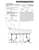
[0015]FIG. 1 is a longitudinal section of an axial-flow compressor for an aircraft gas turbine,
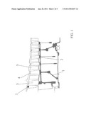
[0016]FIG. 2 is a schematic representation of a flow pulse generator arranged at the compressor casing upstream of the rotor,
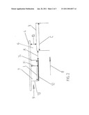
[0017]FIG. 3 is a top view of the flow pulse generator as per FIG. 2, and
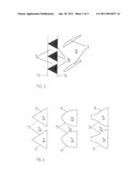
[0018]FIG. 4 shows different variants of flow generators in top view.
[0019]FIG. 1 shows an axial-flow compressor, as used on a gas-turbine engine, which includes several rotors 2 assembled to a rotor drum and connected to a drive shaft 1, as well as stators 5 arranged between the rotor blades 3 and held on the compressor casing 4. A flow pulse generator 7 attached to the inner wall of the compressor casing 4 is associated to the front rotor 2 upstream of and at a certain distance from the rotor gap 6 between the blade tips and the compressor casing 4.
[0020]FIG. 2 shows that the flow pulse generator 7 is arranged in--compared with the main flow 8--a wall-near area of low flow velocitiy 9 at a distance A between the trailing edge 14 of the flow pulse generator 7 and the leading edge of the rotor blades 3. Distance A and length L of the flow pulse generator 7 are approx. 10 to 100% of the chord length S of the rotor blades 3 measured at the blade tip. As the flow pulse generator 7 immediately adjoins the compressor casing 4, there is no air gap between them. Height H of the flow pulse generator is not more than twice the width B of the rotor gap 6.
[0021]The flow pulse generator 7 includes a plurality of circumferentially spacedly arranged pulse channels 7a tapering in flow direction and being established by separators 7b provided on the compressor casing 4 and shaped in accordance with the shape of the pulse channels 7a. In the embodiment shown in FIG. 3, two flow pulse generators 7, i.e. two pulse channels 7a, are provided for each rotor blade passage 10. However, three or four pulse channels 7a may also be associated with a blade passage 10. The separators 7b, which are confined by sidewalls 11 and radially inwards by a thin partition 12, here have a triangular cross-sectional area, with the sidewalls 11 confining the pulse channel 7a having a straight or convexly or concavely curved contour (FIG. 4) to enable diversely formed, tapering and aerodynamically favourable pulse channels 7a to be provided. The cross-sectional area of the pulse channels 7a is preferably rectangular, and the inlet cross-section should be approximately twice the exit cross-section. As regards the vertical cross-sectional area and the shape of the partition 12, the separators 7b, and thus the pulse channels 7a, are preferably formed such that their contour follows the contour of the compressor casing 4. The leading edge 13 of the separators 7b is of an aerodynamically favourable design.
[0022]The flow pulse generators 7 described above are easily manufacturable. Wear or damage as the rotor blades 3 rub in is not to be feared, and compressor efficiency is not affected by increased fluid temperature. Furthermore, the flow pulse is specifically adaptable to the respective flow conditions via the shape, size, contour, number and disposition of the pulse channels 7a, thereby extending the operating range of the axial-flow compressor and increasing the surge limit.
List of Reference Numerals
[0023]1 Drive shaft
[0024]2 Rotors
[0025]3 Rotor blades
[0026]4 Compressor casing
[0027]5 Stators
[0028]6 Rotor gap
[0029]7 Flow pulse generator
[0030]7a Pulse channels
[0031]7b Separators
[0032]8 Main flow
[0033]9 Area of low flow velocity
[0034]10 Rotor blade passage
[0035]11 Sidewall of 7b
[0036]12 Partition of 7b
[0037]13 Leading edge of 7b
[0038]14 Trailing edge of 7b
[0039]A Distance between 3 and 7
[0040]B Width of 6
[0041]H Height of 7
[0042]L Length of 7
[0043]S Chord length of 3
Claims:
1. Axial-flow compressor including, within a compressor casing (4), at
least one rotor (2) of rotor blades (3) connected to a drive shaft (1)
and a stator (5) held on the casing inner wall and, associated to the
rotor gap (6) between the blade tips and the casing inner wail, a flow
pulse generator (7) for stabilizing the rotor gap flow, characterized in
that the flow pulse generator (7) includes pulse channels (7a) arranged
on the inner wall of the casing and extending upstream of the rotor (2)
and tapering in flow direction to accelerate the wall-near flow (9), with
the shape and size of the pulse channels (7a) being determined by
circumferentially spacedly disposed, successive separators (7b) attached
without gap on the casing inner wall.
2. Axial-flow compressor in accordance with claim 1, characterized in that the pulse channels (7a) are each confined by opposite sidewalls (11) of the separators (7b), that the sidewalls (11) have an aerodynamically favourable--straight and/or curved--contour, and that the upstream inflow geometry of the separators (7b) is also aerodynamically favourable.
3. Axial-flow compressor in accordance with claim 1, characterized in that the pulse channels (7a) feature a rectangular cross-section.
4. Axial-flow compressor in accordance with claim 1, characterized in that the inlet cross-sections of the pulse channels (7a) are approximately twice their exit cross-sections.
5. Axial-flow compressor in accordance with claim 1, characterized in that the separators (7b) are covered towards the casing interior by a thin partition (12) separating them from the main flow to the rotors (2).
6. Axial-flow compressor in accordance with claim 5, characterized in that the partition (12) extends axial-parallelly in flow direction or follows the contour of the wall of the compressor casing (4).
7. Axial-flow compressor in accordance with claim 1, characterized in that the pulse channels and separators have a radial height (H) which--at most--is twice the width (B) of the rotor gap (6).
8. Axial-flow compressor in accordance with claim 1, characterized in that the length (L) of the pulse channels and separators in axial direction is between 10 and 100% of the chord length (S) at the rotor blade tip.
9. Axial-flow compressor in accordance with claim 1, characterized in that the pulse channels and separators terminate at a distance (A) to the leading edge of the rotor blades (3) which is between 10 and 100% of the length of the chord (S) at the rotor blade tip.
10. Axial-flow compressor in accordance with claim 1, characterized in that two or more pulse channels (7a) are provided for each rotor blade passage (10) situated between two rotor blades (3).
Description:
[0001]This invention relates to an axial-flow compressor including, within
a compressor casing, at least one rotor of rotor blades connected to a
drive shaft and a stator held on the casing inner wall and, associated to
the rotor gap between the blade tips and the casing inner wall, a flow
pulse generator for stabilizing the rotor gap flow.
[0002]On axial-flow compressors, flow instabilities limiting its operating range may occur in the area of the rotor gap between the rotor blade tips and the compressor casing under high load, for example during strong acceleration of aircraft powered by a gas-turbine engine. A flow pulse generated on the rotor gap enables the gap swirl, which is critical at high compressor load, to be stabilized and, consequently, the operating range of the compressor extended or, respectively, the operating stability thereof improved.
[0003]According to a known measure for actively influencing compressor stability, compressed fluid is tapped from the rearward stages of the compressor and re-introduced in the blade tip area of the forward rotors to increase the flow pulse on the gap and thereby actively influence the rotor gap flow and stabilize the gap swirl. However, this process is disadvantageous in that the re-introduction of hot fluid from the rearward section of the compressor increases the temperature of the fluid in the compressor and, consequently, decreases compressor efficiency.
[0004]Compressor stability is also passively influencable by indentations provided in the compressor casing above the blade tips. A flow circulation effected by the indentation conveys a certain amount of energy into the forward area of the rotor tip, so that the pulse of the rotor inflow is increased and thus the rotor gap flow and ultimately compressor operation are stabilized. Apart from the fact that re-circulation of a certain fluid quantity also in this process entails an increase in temperature, this casing design is difficult to manufacture and is also liable to damage as the rotor rubs in.
[0005]In a broad aspect, the present invention provides, with regard to the flow pulse generator, for the development of an axial-flow compressor of the type specified at the beginning such that, with reduced manufacturing investment and without wear, a high local flow pulse for stabilizing rotor gap flow and compressor operation is achieved.
[0006]It is a particular object of the present invention to provide solution to the above problematics by an axial-flow compressor designed in accordance with the features of patent Claim 1. Advantageous developments and useful embodiments of the present invention become apparent from the sub-claims.
[0007]The present invention, in its essence, provides a flow pulse generator arranged on the inner wall of the compressor casing and including pulse channels extending upstream of the rotor and tapering in flow direction to accelerate the wall-near flow. The shape and size of the pulse channels directed towards the rotor gap is established by circumferentially spacedly disposed, successive separators attached without gap on the casing inner wall. The flow pulse generator so designed is easily manufacturable and ensures favourable inflow of the rotor gap and effective stabilization of the rotor gap flow. The operating range of the compressor is extended without impairing compressor efficiency.
[0008]In a further development of the present invention, the pulse channels are each confined by opposite sidewalls of the separators. The sidewalls have an aerodynamically favourable--straight and/or curved--contour. The upstream inflow geometry of the separators is also aerodynamically favourable.
[0009]In development of the present invention, the pulse channels feature a rectangular cross-section. The inlet cross-sections of the pulse channels are approximately twice their exit cross-sections.
[0010]In an advantageous further development of the present invention, the separators are covered towards the casing interior by a thin partition separating them from the main flow to the rotors. The partition can extend axial-parallelly in flow direction or follow the contour of the wall of the compressor casing.
[0011]In a further development of the present invention, the pulse channels and separators have a radial height which--at most--is twice the width of the rotor gap. The length of the pulse channels and separators in axial direction is between 10 and 100% of the chord length at the rotor blade tip.
[0012]The pulse channels and separators terminate at a distance to the leading edge of the rotor blades which is between 10 and 100% of the length of the chord at the rotor blade tip.
[0013]In a further development of the present invention, two or more pulse channels are provided for each rotor blade passage situated between two rotor blades.
[0014]The present invention is more fully described in light of the accompanying drawing showing a preferred embodiment. In the drawing,
[0015]FIG. 1 is a longitudinal section of an axial-flow compressor for an aircraft gas turbine,
[0016]FIG. 2 is a schematic representation of a flow pulse generator arranged at the compressor casing upstream of the rotor,
[0017]FIG. 3 is a top view of the flow pulse generator as per FIG. 2, and
[0018]FIG. 4 shows different variants of flow generators in top view.
[0019]FIG. 1 shows an axial-flow compressor, as used on a gas-turbine engine, which includes several rotors 2 assembled to a rotor drum and connected to a drive shaft 1, as well as stators 5 arranged between the rotor blades 3 and held on the compressor casing 4. A flow pulse generator 7 attached to the inner wall of the compressor casing 4 is associated to the front rotor 2 upstream of and at a certain distance from the rotor gap 6 between the blade tips and the compressor casing 4.
[0020]FIG. 2 shows that the flow pulse generator 7 is arranged in--compared with the main flow 8--a wall-near area of low flow velocitiy 9 at a distance A between the trailing edge 14 of the flow pulse generator 7 and the leading edge of the rotor blades 3. Distance A and length L of the flow pulse generator 7 are approx. 10 to 100% of the chord length S of the rotor blades 3 measured at the blade tip. As the flow pulse generator 7 immediately adjoins the compressor casing 4, there is no air gap between them. Height H of the flow pulse generator is not more than twice the width B of the rotor gap 6.
[0021]The flow pulse generator 7 includes a plurality of circumferentially spacedly arranged pulse channels 7a tapering in flow direction and being established by separators 7b provided on the compressor casing 4 and shaped in accordance with the shape of the pulse channels 7a. In the embodiment shown in FIG. 3, two flow pulse generators 7, i.e. two pulse channels 7a, are provided for each rotor blade passage 10. However, three or four pulse channels 7a may also be associated with a blade passage 10. The separators 7b, which are confined by sidewalls 11 and radially inwards by a thin partition 12, here have a triangular cross-sectional area, with the sidewalls 11 confining the pulse channel 7a having a straight or convexly or concavely curved contour (FIG. 4) to enable diversely formed, tapering and aerodynamically favourable pulse channels 7a to be provided. The cross-sectional area of the pulse channels 7a is preferably rectangular, and the inlet cross-section should be approximately twice the exit cross-section. As regards the vertical cross-sectional area and the shape of the partition 12, the separators 7b, and thus the pulse channels 7a, are preferably formed such that their contour follows the contour of the compressor casing 4. The leading edge 13 of the separators 7b is of an aerodynamically favourable design.
[0022]The flow pulse generators 7 described above are easily manufacturable. Wear or damage as the rotor blades 3 rub in is not to be feared, and compressor efficiency is not affected by increased fluid temperature. Furthermore, the flow pulse is specifically adaptable to the respective flow conditions via the shape, size, contour, number and disposition of the pulse channels 7a, thereby extending the operating range of the axial-flow compressor and increasing the surge limit.
List of Reference Numerals
[0023]1 Drive shaft
[0024]2 Rotors
[0025]3 Rotor blades
[0026]4 Compressor casing
[0027]5 Stators
[0028]6 Rotor gap
[0029]7 Flow pulse generator
[0030]7a Pulse channels
[0031]7b Separators
[0032]8 Main flow
[0033]9 Area of low flow velocity
[0034]10 Rotor blade passage
[0035]11 Sidewall of 7b
[0036]12 Partition of 7b
[0037]13 Leading edge of 7b
[0038]14 Trailing edge of 7b
[0039]A Distance between 3 and 7
[0040]B Width of 6
[0041]H Height of 7
[0042]L Length of 7
[0043]S Chord length of 3
User Contributions:
Comment about this patent or add new information about this topic:
Images included with this patent application:
 |  |
 |  |
| Similar patent applications: | |
| Date | Title |
|---|---|
| 2010-05-06 | Axial-centrifugal compressor with ported shroud |
| 2010-09-16 | Air bleed in compressor with variable guide vanes |
| 2011-01-20 | Rotary drum of an axial compressor having a composite web |
| 2012-05-10 | Axial compressor and associated operating method |
| 2012-05-10 | Motor driven cabin air compressor with variable diffuser |
| New patent applications in this class: | |
| Date | Title |
|---|---|
| 2016-12-29 | Seal support structures for turbomachines |
| 2016-12-29 | Sealing system for a steam turbine, and steam turbine |
| 2016-07-14 | Large displacement high temperature seal |
| 2016-06-23 | Intergrated seal supports |
| 2016-06-02 | Moment accommodating fastener assembly |
| New patent applications from these inventors: | |
| Date | Title |
|---|---|
| 2018-06-07 | Gas turbine combustion chamber with wall contouring |
| 2018-06-07 | Fuel nozzle of a gas turbine with a swirl generator |
| 2017-06-15 | Method for mounting a combustion chamber of a gas turbine engine |
| 2017-01-26 | Cowling part and combustor assembly for a gas turbine |
| 2017-01-26 | Diffuser part for a gas turbine |
| Top Inventors for class "Rotary kinetic fluid motors or pumps" | |
| Rank | Inventor's name |
|---|---|
| 1 | Gabriel L. Suciu |
| 2 | Frederick M. Schwarz |
| 3 | United Technologies Corporation |
| 4 | Brian D. Merry |
| 5 | Craig M. Beers |