Patent application title: Hair Removal Device
Inventors:
Matthias Huisinga (Giessen, DE)
Joachim Nickel (Waldems, DE)
IPC8 Class: AA45D2600FI
USPC Class:
606133
Class name: Instruments means for removal of skin or material therefrom physical removal of hair or hair plugs from skin
Publication date: 2010-11-04
Patent application number: 20100280527
concerned with a hair removal device that
comprises a hair removal unit, a cap element having a skin contacting
surface that extends at least on a side of the hair removal unit, and
wherein elongated and elevated structures are arranged on the skin
contacting surface, which elongated and elevated structures all extend
essentially parallel to each other. Such a hair removal device is
specifically beneficial for application on wet skin.Claims:
1. Hair removal device comprising:a hair removal unit;a cap element having
a skin contacting surface that extends at least on a side of the hair
removal unit;wherein elongated and elevated structures are arranged on
the skin contacting surface, which elongated and elevated structures all
extend essentially parallel to each other.
2. Hair removal device according to claim 1, wherein the elongated and elevated structures are linear.
3. Hair removal device according to claim 2, wherein the elongated and elevated structures have a height of about 0.1 mm to about 1 mm.
4. Hair removal device according to claim 2, wherein the elongated and elevated structures have a height of about 0.21 mm to about 0.6 mm.
5. Hair removal device according to claim 1, wherein the skin contacting surface has an average surface roughness of about 0.5 μm to about 5 μm, and preferably of about 1 μm to about 3 μm and even more preferably of about 2.0 μm to about 2.5 μm.
6. Hair removal device according to claim 1 , wherein the elongated and elevated structures have a quadratic, triangular, circular, or trapezoidal cross section.
7. Hair removal device according to claim 3, wherein the height of the elongated and elevated structures increases with increasing distance to the hair removal unit.
8. Hair removal device according to claim 4, wherein the skin contacting surface also extends at the sides of the hair removal unit.
9. Hair removal device according to claim 1, wherein the cap element is detachable.
10. Hair removal device according to claim 1, wherein the hair removal device is an epilator device and the hair removal unit is an epilation unit.
11. Cap element intended for removable attachment to a housing of a hair removal device, which cap element has a mounting structure that is arranged so as to detachably mate with a mounting structure of the housing, which cap element has a skin contacting surface on which elongated and elevated structures are arranged that all extend essentially parallel to each other.
12. Kit comprising:a housing of a hair removal device comprising a hair removal unit arranged at the housing; anda cap element of a hair removal device intended for detachable attachment onto the housing, which cap element has a skin contacting surface on which elongated and elevated structures are arranged that all extend essentially parallel to each other.Description:
FIELD OF THE INVENTION
[0001]The present invention relates to hair removal devices, specifically those comprising a hair removal unit and a cap element having a skin contacting surface.
BACKGROUND OF THE INVENTION
[0002]The Braun Silk epil Xpressive epilator device has several detachable cap elements that can be attached over the epilation cylinder. One such cap element (the so called efficiency cap element) has a skin contacting surface that is flat. It was found that the flat skin contacting surface is inconvenient to use on partially wet skin as the alternately wet and dry skin areas lead to a jerky gliding operation.
SUMMARY OF THE INVENTION
[0003]It is hence desirable to improve the known hair removal device specifically with respect to better use on wet or partially wet skin.
[0004]An improved hair removal device is provided according to claim 1. Further embodiments are defined by the dependent claims.
[0005]A hair removal device as proposed comprises a hair removal unit and a cap element that has a skin contacting surface that is intended to contact the skin during regular operation. The skin contacting surface extends at least on a side the hair removal unit. The skin contacting surface may extends at least behind the hair removal unit, where "behind" is defined with respect to a preferred use direction of the hair removal device. Elongated and elevated structures are arranged on the skin contacting surface, which elongated and elevated structures all extend essentially parallel to each other. In a refinement, the elongated and elevated structures are linear structures. A preferred use direction of the hair removal device is defined by the direction into which the elongated and elevated structures extend as the gliding properties of the skin contacting surface over wet or partially wet skin is optimal if the hair removal device is drawn over the skin along the extension direction of the elongated and elevated structures (which hence is the preferred use direction).
[0006]In an embodiment, the elongated and elevated structures have a height between about 0.1 mm and about 1 mm, in particular between about 0.2 mm and about 0.6 mm. These height values specifically support the gliding properties of the skin contacting surface over wet or partially wet skin.
[0007]In another embodiment, the skin contacting surface has an average surface roughness of about 0.5 μm to about 5 μm, preferably between 1 μm and about 3 μm, and even more preferably between 2.0 μm and about 2.5 μm. Such a microstructure of the skin contacting surface was found to enhance the gliding properties of the cap element over wet or partially wet skin.
[0008]In a further embodiment, the elongated and elevated structures have a cross section (taken perpendicular to their extension direction) that is quadratic, triangular, circular, or trapezoidal, where it is understood that these cross sections may be modified in particular because of necessary rounded edges to e.g. enhance the removal of the cap element from a mould.
[0009]In an even further embodiment, the height of the elongated and elevated structures increases with increasing distance to the hair removal unit. This specifically allows for close contact of the hair removal unit with the skin or hairs growing on the skin during regular operation, while the gliding properties on wet skin are enhanced.
[0010]In a different embodiment, the skin contacting surface extends also at the sides of the hair removal unit (i.e. the skin contacting surface surrounds the hair removal unit at three sides). The skin contacting surface may further enclose the hair removal unit (i.e. the skin contacting surface may extend at all four sides of the hair removal unit).
[0011]In an embodiment, the cap element is detachable.
[0012]In another embodiment, the hair removal device is an epilator device and the hair removal unit is an epilation unit. In such a case, the preferred use direction is defined by the rotation direction of an epilation cylinder being part of the epilation unit. The preferred use direction is such that the rotating epilation cylinder surface moves towards the hairs growing on the skin when the epilator device is drawn over the skin along the preferred use direction.
[0013]The invention is further concerned with a cap element of a hair removal device and a kit that comprises such a cap element and a housing of a hair removal device.
BRIEF DESCRIPTION OF THE DRAWINGS
[0014]The invention will be further elucidated by detailed discussion of an exemplary embodiment and by reference to figures. In the figures
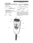
[0015]FIG. 1 is a perspective view onto an exemplary hair removal device realized as an epilator device;
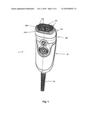
[0016]FIG. 2 is a perspective view onto the head area of the hair removal device shown in FIG. 1,
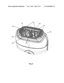
[0017]FIG. 3 is a perspective view onto a detachable cap element comprising a skin contacting surface having elongated and elevated structures;
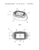
[0018]FIG. 4 is a top view onto the detachable cap element as shown in FIG. 3;
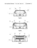
[0019]FIG. 5A is a first cross sectional image of the cap element shown in FIGS. 3 and 4 along line A-A as indicated in FIG. 4;
[0020]FIG. 5B is a second cross sectional image of the cap element shown in FIGS. 3 and 4 along line B-B as indicated in FIG. 4; and
[0021]FIG. 5c is a third cross sectional image of the cap element shown in FIGS. 3 and 4 along line C-C as indicated in FIG. 4.
DETAILED DESCRIPTION OF THE INVENTION
[0022]FIG. 1 is a perspective view onto an exemplary embodiment of a hair removal device 1 as proposed. The hair removal device 1 comprises a hand piece part 10 and a head part 100, the head part 100 comprises a detachable cap element 110 and a hair removal unit 120 that extends into an aperture of the cap element 110. The cap element 110 comprises a skin contacting surface 111 on which elongated and elevated structures 112 are arranged. The cap element 110 further comprises a comb structure 119 for erecting hairs during operation of the device such that hairs are fed towards the hair removal unit 120. The hair removal device 1 is connected to mains voltage via a cord 19, even though the hair removal device 1 may alternatively or additionally be equipped with a (rechargeable) battery for cordless operation. In the exemplary embodiment as shown, the hair removal device 1 is realized as an epilator device and the hair removal unit 120 is realized as an epilation unit comprising an epilation cylinder intended for gripping and plucking hairs from the skin during operation. It is to be noted that the cap element 110 may also be arranged as an integral part of the hair removal device 1 (which means that the cap element 110 would then not be detachable).
[0023]FIG. 2 is a magnification of a head area of the hair removal device 1 as shown in FIG. 1 for better visibility of details of the head area. The hair removal unit 120 (realized as an epilation unit comprising an epilation cylinder) comprises a plurality of pairs of tweezers 121 that are arranged to grip hairs during operation and to pluck the gripped hairs out from the skin as is generally known in the art. The detachable cap element 110 comprises a (continuous) skin contacting surface 111 that around three sides of the aperture 113 into which the hair removal unit 120 extends. Elongated and elevated structures 112 are arranged on the skin contacting surface 111, which all extend essentially parallel to each other in an extension direction. The extension direction also coincides with a use direction of the hair removal device. The use direction coincides with the extension direction of the elongated and elevated structures as the gliding properties of the skin contacting surface 111 is optimal when the hair removal device is drawn over the skin along the preferred use direction. The comb structure 119 is arranged near the hair removal unit 120. Hence, a preferred use direction D is defined by the location of the comb structure as the comb structure should first erect and align hairs before the hairs are removed. Hence, the hair removal device should preferably be drawn over the skin along the preferred use direction D to effectuate erection and alignment of hairs prior to the hair removal performed by the hair removal unit 120. The preferred use direction D may also be determined by the rotation direction of the epilation cylinder in the present embodiment. The pairs of tweezers are actuated to close at a certain angular position with respect to the skin contacting surface 111 that essentially defines a plane. The closed pairs of tweezers that may have gripped hairs continue to rotate in the closed position so that the gripped hairs are plucked out from the skin. The use of the hair removal device is hence optimized when the hair removal device is drawn over the skin along the preferred use direction D as the hairs will feed into the gaps between the pairs of tweezers in their open position before they close, while the open clamping element move towards the hairs in the preferred use direction D. With respect to the preferred use direction D, the skin contacting surface 111 at least extends behind the hair removal unit 120, but the skin contacting surface 111 may extend around three sides or all four sides of the hair removal unit 120. The comb structure 119 is intended to erect the hairs and to align the hairs with the direction of the gaps between the pairs of tweezers prior to the hairs being gripped. This increases the gripping and hence plucking efficiency of the epilator device. The comb structure 119 can only perform its task when it is arranged before the hair removal unit 120 with respect to the preferred use direction D.
[0024]The elongated and elevated structures 112 extend essentially parallel to the preferred use direction D on the skin contacting surface 111. This macrostructure enhance the gliding properties of the skin contacting surface over a wet or partially wet skin. A flat, essentially untextured skin contacting surface as was used so far was found to lead to a jerky operation due to ruptures of the liquid film between skin surface and skin contacting surface.
[0025]FIG. 3 is a perspective view onto the detached cap element 110. In the shown embodiment, the cap element 110 comprises an outer cover 130 that is intended to be attached to the head part 100. It further comprises an inner cover 131 that is mounted at the outer cover 130 so as to allow for a swiveling motion of the inner cover 131 with respect to the outer cover 130. The inner cover 131 has an aperture 113 that provides an opening into which the hair removal unit 120 extends in the attached state to contact the skin. The inner cover 131 further comprises the skin contacting surface 111 on which the elongated and elevated structures 112 are arranged.
[0026]In contrast to the shown embodiment, a hair removal device as proposed may not be assembled from a hand piece part and a head part, which head part comprises a cap element. In another embodiment, the skin contacting surface 111 is an integral part of a housing of the hair removal device.
[0027]FIG. 4 is a top view onto the cap element 110 as shown in FIG. 3. The preferred use direction D is indicated. The comb structure 119 is arranged before the aperture 113 with respect to the preferred use direction D. The skin contacting surface 111 extends besides and behind the aperture 113 with respect to the preferred use direction D. In another embodiment, the skin contacting surface 111 extends also before the aperture 113 instead of a comb structure 119 (the skin contacting surface 111 then surrounds the aperture 113). The elongated and elevated structures 112 extend parallel to the preferred use direction D.
[0028]FIGS. 5A, 5B, and 5C are cross sectional cuts through the cap element 110 along the lines A-A, B-B, and C-C, respectively, as indicated in FIG. 4.
[0029]FIG. 5A is a cross sectional cut through the cap element 110 along line A-A as indicated in FIG. 4. The line A-A is positioned behind the aperture 113 with respect to the preferred use direction D. The skin contacting surface 111 comprises elongated and elevated structures 112. The elongated and elevated structures 112 have a rounded trapezoidal cross section. In other embodiments, the cross section of the elongated and elevated structures 112 may be triangular, rectangular, or circular or the cross sections may have different cross sections that may differ between neighboring elongated and elevated structures 112 and/or the cross section of an elongated and elevated structure 112 may change over its extension length. The height h of the elongated and elevated structures at the position of line A-A is about 0.5 mm in the shown embodiment.
[0030]FIG. 5B is a cross sectional cut through the cap element 110 along line B-B as indicated in FIG. 4. The line B-B is positioned within the extension of the aperture 113. The elongated and elevated structures 112 that are arranged on the skin contacting surface 111 on the sides of the aperture 113 have a height of about 0.2 mm in the shown embodiment. This shows that the height of the elongated and elevated structures may vary and specifically may increase with increasing distance to the hair removal unit (or with increasing distance to the aperture or opening 113). A growing height of the elongated and elevated structures 112 supports the gliding properties of the skin contacting surface over a wet or partially wet skin. A low height h of the elongated and elevated structures 112 around the aperture 113 supports that hairs can be removed as close at the skin surface as possible.
[0031]FIG. 5c is a cross sectional cut through the cap element 110 along line C-C as indicated in FIG. 4. The line C-C is positioned before the aperture 113 with respect to the preferred use direction D and cuts through the comb structure 119. The height h' of the comb teeth is such that the flexible skin cannot substantially enter into the gaps between the comb teeth and it is hence effectuated that hairs are erected and aligned for being optimally fed to the hair removal unit. Hence, the comb structure 119 does not represent a continuous skin contacting surface, but only the top parts of the comb teeth get in contact with the skin. The height h' of the comb teeth is substantially larger than 1 mm, e.g. the height may be about 2 mm (i.e. the height value is twice as large as the maximum preferred height h of the elongated and elevated structures 112) or 3 mm or 4 mm or even larger.
[0032]Further to the above, the elongated and elevated structures 112 raise at their two ends out of the continuous skin contacting surface to the respective height h so that the skin contacting surface 111 has a frontal edge and a back edge that are essentially unstructured. The distance of the elongated and elevated structures perpendicular to their extension direction may be about 0.5 mm to 2 mm, in particular the distance may be between about 1.0 mm and 1.5 mm. The frontal edge and the back edge of the trimmer comb necessarily are structured (alternate arrangement of teeth and cut-outs) to perform the combing task.
[0033]The material of the skin contacting surface 111 and of the elongated and elevated structures 112 may be polycarbonate (PC). Other parts of the cap element 110 may be made of polyamide (e.g. PA66). The gliding properties of the skin contacting surface (which includes the surface of the elongated and elevated structures arranged on the skin contacting surface) can be enhanced by a microstructure of the surface, e.g. the skin contacting surface 111 may have an average surface roughness (generally abbreviated by Ra) of about Ra=0.5-5 μm according to VDI 3400. The average surface roughness may in particular be chosen to lie in a range of Ra=1 μm-3 μm and it may even more particularly be chosen to lie in a range of Ra=2 μm-2.5 μm. The average surface roughness may be achieved by an according erosion process when making the mould for the cap element 110 so that the surface roughness of the mould is impressed into the skin contacting surface.
[0034]The dimensions and values disclosed herein are not to be understood as being strictly limited to the exact numerical values recited. Instead, unless otherwise specified, each such dimension is intended to mean both the recited value and a functionally equivalent range surrounding that value. For example, a dimension disclosed as "40 mm" is intended to mean "about 40 mm."
Claims:
1. Hair removal device comprising:a hair removal unit;a cap element having
a skin contacting surface that extends at least on a side of the hair
removal unit;wherein elongated and elevated structures are arranged on
the skin contacting surface, which elongated and elevated structures all
extend essentially parallel to each other.
2. Hair removal device according to claim 1, wherein the elongated and elevated structures are linear.
3. Hair removal device according to claim 2, wherein the elongated and elevated structures have a height of about 0.1 mm to about 1 mm.
4. Hair removal device according to claim 2, wherein the elongated and elevated structures have a height of about 0.21 mm to about 0.6 mm.
5. Hair removal device according to claim 1, wherein the skin contacting surface has an average surface roughness of about 0.5 μm to about 5 μm, and preferably of about 1 μm to about 3 μm and even more preferably of about 2.0 μm to about 2.5 μm.
6. Hair removal device according to claim 1 , wherein the elongated and elevated structures have a quadratic, triangular, circular, or trapezoidal cross section.
7. Hair removal device according to claim 3, wherein the height of the elongated and elevated structures increases with increasing distance to the hair removal unit.
8. Hair removal device according to claim 4, wherein the skin contacting surface also extends at the sides of the hair removal unit.
9. Hair removal device according to claim 1, wherein the cap element is detachable.
10. Hair removal device according to claim 1, wherein the hair removal device is an epilator device and the hair removal unit is an epilation unit.
11. Cap element intended for removable attachment to a housing of a hair removal device, which cap element has a mounting structure that is arranged so as to detachably mate with a mounting structure of the housing, which cap element has a skin contacting surface on which elongated and elevated structures are arranged that all extend essentially parallel to each other.
12. Kit comprising:a housing of a hair removal device comprising a hair removal unit arranged at the housing; anda cap element of a hair removal device intended for detachable attachment onto the housing, which cap element has a skin contacting surface on which elongated and elevated structures are arranged that all extend essentially parallel to each other.
Description:
FIELD OF THE INVENTION
[0001]The present invention relates to hair removal devices, specifically those comprising a hair removal unit and a cap element having a skin contacting surface.
BACKGROUND OF THE INVENTION
[0002]The Braun Silk epil Xpressive epilator device has several detachable cap elements that can be attached over the epilation cylinder. One such cap element (the so called efficiency cap element) has a skin contacting surface that is flat. It was found that the flat skin contacting surface is inconvenient to use on partially wet skin as the alternately wet and dry skin areas lead to a jerky gliding operation.
SUMMARY OF THE INVENTION
[0003]It is hence desirable to improve the known hair removal device specifically with respect to better use on wet or partially wet skin.
[0004]An improved hair removal device is provided according to claim 1. Further embodiments are defined by the dependent claims.
[0005]A hair removal device as proposed comprises a hair removal unit and a cap element that has a skin contacting surface that is intended to contact the skin during regular operation. The skin contacting surface extends at least on a side the hair removal unit. The skin contacting surface may extends at least behind the hair removal unit, where "behind" is defined with respect to a preferred use direction of the hair removal device. Elongated and elevated structures are arranged on the skin contacting surface, which elongated and elevated structures all extend essentially parallel to each other. In a refinement, the elongated and elevated structures are linear structures. A preferred use direction of the hair removal device is defined by the direction into which the elongated and elevated structures extend as the gliding properties of the skin contacting surface over wet or partially wet skin is optimal if the hair removal device is drawn over the skin along the extension direction of the elongated and elevated structures (which hence is the preferred use direction).
[0006]In an embodiment, the elongated and elevated structures have a height between about 0.1 mm and about 1 mm, in particular between about 0.2 mm and about 0.6 mm. These height values specifically support the gliding properties of the skin contacting surface over wet or partially wet skin.
[0007]In another embodiment, the skin contacting surface has an average surface roughness of about 0.5 μm to about 5 μm, preferably between 1 μm and about 3 μm, and even more preferably between 2.0 μm and about 2.5 μm. Such a microstructure of the skin contacting surface was found to enhance the gliding properties of the cap element over wet or partially wet skin.
[0008]In a further embodiment, the elongated and elevated structures have a cross section (taken perpendicular to their extension direction) that is quadratic, triangular, circular, or trapezoidal, where it is understood that these cross sections may be modified in particular because of necessary rounded edges to e.g. enhance the removal of the cap element from a mould.
[0009]In an even further embodiment, the height of the elongated and elevated structures increases with increasing distance to the hair removal unit. This specifically allows for close contact of the hair removal unit with the skin or hairs growing on the skin during regular operation, while the gliding properties on wet skin are enhanced.
[0010]In a different embodiment, the skin contacting surface extends also at the sides of the hair removal unit (i.e. the skin contacting surface surrounds the hair removal unit at three sides). The skin contacting surface may further enclose the hair removal unit (i.e. the skin contacting surface may extend at all four sides of the hair removal unit).
[0011]In an embodiment, the cap element is detachable.
[0012]In another embodiment, the hair removal device is an epilator device and the hair removal unit is an epilation unit. In such a case, the preferred use direction is defined by the rotation direction of an epilation cylinder being part of the epilation unit. The preferred use direction is such that the rotating epilation cylinder surface moves towards the hairs growing on the skin when the epilator device is drawn over the skin along the preferred use direction.
[0013]The invention is further concerned with a cap element of a hair removal device and a kit that comprises such a cap element and a housing of a hair removal device.
BRIEF DESCRIPTION OF THE DRAWINGS
[0014]The invention will be further elucidated by detailed discussion of an exemplary embodiment and by reference to figures. In the figures
[0015]FIG. 1 is a perspective view onto an exemplary hair removal device realized as an epilator device;
[0016]FIG. 2 is a perspective view onto the head area of the hair removal device shown in FIG. 1,
[0017]FIG. 3 is a perspective view onto a detachable cap element comprising a skin contacting surface having elongated and elevated structures;
[0018]FIG. 4 is a top view onto the detachable cap element as shown in FIG. 3;
[0019]FIG. 5A is a first cross sectional image of the cap element shown in FIGS. 3 and 4 along line A-A as indicated in FIG. 4;
[0020]FIG. 5B is a second cross sectional image of the cap element shown in FIGS. 3 and 4 along line B-B as indicated in FIG. 4; and
[0021]FIG. 5c is a third cross sectional image of the cap element shown in FIGS. 3 and 4 along line C-C as indicated in FIG. 4.
DETAILED DESCRIPTION OF THE INVENTION
[0022]FIG. 1 is a perspective view onto an exemplary embodiment of a hair removal device 1 as proposed. The hair removal device 1 comprises a hand piece part 10 and a head part 100, the head part 100 comprises a detachable cap element 110 and a hair removal unit 120 that extends into an aperture of the cap element 110. The cap element 110 comprises a skin contacting surface 111 on which elongated and elevated structures 112 are arranged. The cap element 110 further comprises a comb structure 119 for erecting hairs during operation of the device such that hairs are fed towards the hair removal unit 120. The hair removal device 1 is connected to mains voltage via a cord 19, even though the hair removal device 1 may alternatively or additionally be equipped with a (rechargeable) battery for cordless operation. In the exemplary embodiment as shown, the hair removal device 1 is realized as an epilator device and the hair removal unit 120 is realized as an epilation unit comprising an epilation cylinder intended for gripping and plucking hairs from the skin during operation. It is to be noted that the cap element 110 may also be arranged as an integral part of the hair removal device 1 (which means that the cap element 110 would then not be detachable).
[0023]FIG. 2 is a magnification of a head area of the hair removal device 1 as shown in FIG. 1 for better visibility of details of the head area. The hair removal unit 120 (realized as an epilation unit comprising an epilation cylinder) comprises a plurality of pairs of tweezers 121 that are arranged to grip hairs during operation and to pluck the gripped hairs out from the skin as is generally known in the art. The detachable cap element 110 comprises a (continuous) skin contacting surface 111 that around three sides of the aperture 113 into which the hair removal unit 120 extends. Elongated and elevated structures 112 are arranged on the skin contacting surface 111, which all extend essentially parallel to each other in an extension direction. The extension direction also coincides with a use direction of the hair removal device. The use direction coincides with the extension direction of the elongated and elevated structures as the gliding properties of the skin contacting surface 111 is optimal when the hair removal device is drawn over the skin along the preferred use direction. The comb structure 119 is arranged near the hair removal unit 120. Hence, a preferred use direction D is defined by the location of the comb structure as the comb structure should first erect and align hairs before the hairs are removed. Hence, the hair removal device should preferably be drawn over the skin along the preferred use direction D to effectuate erection and alignment of hairs prior to the hair removal performed by the hair removal unit 120. The preferred use direction D may also be determined by the rotation direction of the epilation cylinder in the present embodiment. The pairs of tweezers are actuated to close at a certain angular position with respect to the skin contacting surface 111 that essentially defines a plane. The closed pairs of tweezers that may have gripped hairs continue to rotate in the closed position so that the gripped hairs are plucked out from the skin. The use of the hair removal device is hence optimized when the hair removal device is drawn over the skin along the preferred use direction D as the hairs will feed into the gaps between the pairs of tweezers in their open position before they close, while the open clamping element move towards the hairs in the preferred use direction D. With respect to the preferred use direction D, the skin contacting surface 111 at least extends behind the hair removal unit 120, but the skin contacting surface 111 may extend around three sides or all four sides of the hair removal unit 120. The comb structure 119 is intended to erect the hairs and to align the hairs with the direction of the gaps between the pairs of tweezers prior to the hairs being gripped. This increases the gripping and hence plucking efficiency of the epilator device. The comb structure 119 can only perform its task when it is arranged before the hair removal unit 120 with respect to the preferred use direction D.
[0024]The elongated and elevated structures 112 extend essentially parallel to the preferred use direction D on the skin contacting surface 111. This macrostructure enhance the gliding properties of the skin contacting surface over a wet or partially wet skin. A flat, essentially untextured skin contacting surface as was used so far was found to lead to a jerky operation due to ruptures of the liquid film between skin surface and skin contacting surface.
[0025]FIG. 3 is a perspective view onto the detached cap element 110. In the shown embodiment, the cap element 110 comprises an outer cover 130 that is intended to be attached to the head part 100. It further comprises an inner cover 131 that is mounted at the outer cover 130 so as to allow for a swiveling motion of the inner cover 131 with respect to the outer cover 130. The inner cover 131 has an aperture 113 that provides an opening into which the hair removal unit 120 extends in the attached state to contact the skin. The inner cover 131 further comprises the skin contacting surface 111 on which the elongated and elevated structures 112 are arranged.
[0026]In contrast to the shown embodiment, a hair removal device as proposed may not be assembled from a hand piece part and a head part, which head part comprises a cap element. In another embodiment, the skin contacting surface 111 is an integral part of a housing of the hair removal device.
[0027]FIG. 4 is a top view onto the cap element 110 as shown in FIG. 3. The preferred use direction D is indicated. The comb structure 119 is arranged before the aperture 113 with respect to the preferred use direction D. The skin contacting surface 111 extends besides and behind the aperture 113 with respect to the preferred use direction D. In another embodiment, the skin contacting surface 111 extends also before the aperture 113 instead of a comb structure 119 (the skin contacting surface 111 then surrounds the aperture 113). The elongated and elevated structures 112 extend parallel to the preferred use direction D.
[0028]FIGS. 5A, 5B, and 5C are cross sectional cuts through the cap element 110 along the lines A-A, B-B, and C-C, respectively, as indicated in FIG. 4.
[0029]FIG. 5A is a cross sectional cut through the cap element 110 along line A-A as indicated in FIG. 4. The line A-A is positioned behind the aperture 113 with respect to the preferred use direction D. The skin contacting surface 111 comprises elongated and elevated structures 112. The elongated and elevated structures 112 have a rounded trapezoidal cross section. In other embodiments, the cross section of the elongated and elevated structures 112 may be triangular, rectangular, or circular or the cross sections may have different cross sections that may differ between neighboring elongated and elevated structures 112 and/or the cross section of an elongated and elevated structure 112 may change over its extension length. The height h of the elongated and elevated structures at the position of line A-A is about 0.5 mm in the shown embodiment.
[0030]FIG. 5B is a cross sectional cut through the cap element 110 along line B-B as indicated in FIG. 4. The line B-B is positioned within the extension of the aperture 113. The elongated and elevated structures 112 that are arranged on the skin contacting surface 111 on the sides of the aperture 113 have a height of about 0.2 mm in the shown embodiment. This shows that the height of the elongated and elevated structures may vary and specifically may increase with increasing distance to the hair removal unit (or with increasing distance to the aperture or opening 113). A growing height of the elongated and elevated structures 112 supports the gliding properties of the skin contacting surface over a wet or partially wet skin. A low height h of the elongated and elevated structures 112 around the aperture 113 supports that hairs can be removed as close at the skin surface as possible.
[0031]FIG. 5c is a cross sectional cut through the cap element 110 along line C-C as indicated in FIG. 4. The line C-C is positioned before the aperture 113 with respect to the preferred use direction D and cuts through the comb structure 119. The height h' of the comb teeth is such that the flexible skin cannot substantially enter into the gaps between the comb teeth and it is hence effectuated that hairs are erected and aligned for being optimally fed to the hair removal unit. Hence, the comb structure 119 does not represent a continuous skin contacting surface, but only the top parts of the comb teeth get in contact with the skin. The height h' of the comb teeth is substantially larger than 1 mm, e.g. the height may be about 2 mm (i.e. the height value is twice as large as the maximum preferred height h of the elongated and elevated structures 112) or 3 mm or 4 mm or even larger.
[0032]Further to the above, the elongated and elevated structures 112 raise at their two ends out of the continuous skin contacting surface to the respective height h so that the skin contacting surface 111 has a frontal edge and a back edge that are essentially unstructured. The distance of the elongated and elevated structures perpendicular to their extension direction may be about 0.5 mm to 2 mm, in particular the distance may be between about 1.0 mm and 1.5 mm. The frontal edge and the back edge of the trimmer comb necessarily are structured (alternate arrangement of teeth and cut-outs) to perform the combing task.
[0033]The material of the skin contacting surface 111 and of the elongated and elevated structures 112 may be polycarbonate (PC). Other parts of the cap element 110 may be made of polyamide (e.g. PA66). The gliding properties of the skin contacting surface (which includes the surface of the elongated and elevated structures arranged on the skin contacting surface) can be enhanced by a microstructure of the surface, e.g. the skin contacting surface 111 may have an average surface roughness (generally abbreviated by Ra) of about Ra=0.5-5 μm according to VDI 3400. The average surface roughness may in particular be chosen to lie in a range of Ra=1 μm-3 μm and it may even more particularly be chosen to lie in a range of Ra=2 μm-2.5 μm. The average surface roughness may be achieved by an according erosion process when making the mould for the cap element 110 so that the surface roughness of the mould is impressed into the skin contacting surface.
[0034]The dimensions and values disclosed herein are not to be understood as being strictly limited to the exact numerical values recited. Instead, unless otherwise specified, each such dimension is intended to mean both the recited value and a functionally equivalent range surrounding that value. For example, a dimension disclosed as "40 mm" is intended to mean "about 40 mm."
User Contributions:
Comment about this patent or add new information about this topic:
Images included with this patent application:
 |  |
 |  |
 |
| Similar patent applications: | |
| Date | Title |
|---|---|
| 2011-09-29 | Hair removal device |
| 2012-02-09 | Hair removal device |
| 2013-12-12 | Hair removal device |
| 2009-06-04 | Filter removal device |
| 2013-01-17 | Thrombus removal device |
| New patent applications in this class: | |
| Date | Title |
|---|---|
| 2016-09-01 | Follicle punch for use with curled follicles |
| 2016-06-16 | Mechanized punch for cylindrical excision of hair follicles |
| 2016-05-26 | Hair removal apparatus |
| 2016-01-07 | Hair removal tool |
| 2015-11-12 | Technique and apparatus for extracting ingrown hairs that cause razor bumps |
| New patent applications from these inventors: | |
| Date | Title |
|---|---|
| 2010-11-04 | Skin treatment device and attachment |
| Top Inventors for class "Surgery" | |
| Rank | Inventor's name |
|---|---|
| 1 | Lutz Biedermann |
| 2 | Roger P. Jackson |
| 3 | Wilfried Matthis |
| 4 | Frederick E. Shelton, Iv |
| 5 | Joseph D. Brannan |