Patent application title: ELECTRIC DRIVE FOR A MOBILE VEHICLE
Inventors:
Stefan Anspann (Nurnberg, DE)
Robert Pauli (Salzweg, DE)
Assignees:
ZF FRIEDRICHSHAFEN AG
IPC8 Class: AF16H372FI
USPC Class:
475150
Class name: Planetary gear transmission systems or components electric or magnetic drive or control differential drive or control
Publication date: 2010-10-14
Patent application number: 20100261566
obile vehicle comprises an electric motor (1)
which powers a differential via a spur gear mechanism (3, 4, 6, 7). The
electric motor (1), the spur gear mechanism (3, 4, 6, 7) and the
differential (9) are each accommodated within a housing comprising three
main housing portions (12, 13, 14), namely, a central housing portion
(12), a first covering housing portion (13) and a second covering housing
portion (14).Claims:
1-10. (canceled)
11. An electric drive for a mobile vehicle with an electric motor (1) which powers first and second drive outputs (10, 11) via a spur gear mechanism (3, 4, 6, 7) and a differential (9) such that a housing encloses the differential (9), the spur gear mechanism (3, 4, 6, 7) and the electric motor (1);the housing comprising a central housing portion (12), a first covering housing portion (13) and a second covering housing portion (14) such that the central housing portion (12) being a one-piece housing comprising a cylindrical expanded section (15) accommodating the electric motor (1), the central housing portion (12) being closed at one end by the first covering housing portion (13) and having, at an opposite end, an expanded section (16) extending parallel to the cylindrical expanded section (15), in which the differential (9) and the spur gear mechanism (3, 4, 6, 7) are accommodated, and the expanded section (16) being closed by the second covering housing portion (14);the electric motor (1) comprising a motor shaft (2) such that the motor shaft (2) is mounted in the central housing portion (12), the motor shaft (2) being also mounted to rotate in the first covering housing portion (13) and in the second covering housing portion (14), and the motor shaft (2) and a first spur gear (3) being integrally connected with one another; anda parking lock gearwheel of a parking lock being arranged on the motor shaft (2).
12. The electric drive according to claim 11, wherein the spur gear mechanism comprises first, second, third and fourth spur gears, the first spur gear (3) is connected, in a rotationally fixed manner, to the motor shaft (2), the second spur gear (4) is in active engagement with the first spur gear (3) and is connected, in a rotationally fixed manner, to an intermediate shaft (5), the third spur gear (6) is also connected, in a rotationally fixed manner, to the intermediate shaft (5) and is in active engagement with the fourth spur gear (7), and the fourth spur gear (7) is connected, in a rotationally fixed manner, to the differential (9).
13. The electric drive according to claim 11, wherein an intermediate shaft (5) is mounted to rotate in both the second covering housing portion (14) and the central housing portion (12).
14. The electric drive according to claim 11, wherein the differential (9) is mounted to rotate in both the second covering housing portion (14) and the central housing portion (12).
15. The electric drive according to claim 11, wherein rotational axes of the first and the second drive outputs (10, 11) are orientated parallel to a rotational axis of the motor shaft (2).
16. The electric drive according to claim 11, wherein cooling ducts are arranged in the central housing portion (12).
17. The electric drive according to claim 12, wherein the fourth spur gear (7) is connected, by a continuous-material joint, to a differential cage (8) of the differential (9).
18. The electric drive according to claim 11, wherein a first bearing point (19) of the motor shaft (2) is arranged at one end of the motor shaft (2), a second bearing point (18) is arranged between a rotor of the electric motor (1) and a first spur gear (3), and a third bearing point (17) is arranged at an other end of the motor shaft (2).
19. The electric drive according to claim 11, wherein four main cooling ducts, arranged parallel to a rotational axis of the motor shaft (2), are located within the central housing portion (12), the four main cooling ducts are located between a round rotor of the electric motor (1) and a square outer contour of the central housing portion (12) which encloses the electric motor (1).
20. An electric drive for a mobile vehicle comprising:an electric motor (1) which powers first and second drive outputs (10, 11) via first, second, third and fourth spur gears (3, 4, 6, 7) and a differential (9),a housing encloses the differential (9), the first, the second, the third and the fourth spur gears (3, 4, 6, 7) and the motor (1), the housing comprising a central housing portion (12), a first covering housing portion (13) and a second covering housing portion (14), the central housing portion (12) comprises a cylindrical expanded section (15) accommodating the electric motor (1), a first end of the central housing portion (12) being enclosed by the first covering housing portion (13) and an opposite second end of the central housing portion (12) comprising a second expanded section (16) that expands parallel to the cylindrical expanded section (15), the differential (9) and the first, the second, the third and the fourth spur gears (3, 4, 6, 7) being accommodated within the second expanded section (16), the second expanded section (16) being enclosed by the second covering housing portion (14), the motor (1) comprising a motor shaft (2) which is rotationally supported by a bearing (17) in the first covering housing portion (13) and another bearing (19) in the second covering housing portion (14),the motor shaft (2) and the first spur gear (3) are integrally connected to one another, anda parking lock gearwheel of a parking lock is arranged on the motor shaft (2).Description:
[0001]This application is a National Stage completion of PCT/EP2008/065641
filed Nov. 17, 2008, which claims priority from German patent application
serial no. 10 2007 055 767.3 filed Dec. 12, 2007.
FIELD OF THE INVENTION
[0002]Electric drives for mobile vehicles are used for example as stand-alone drives or as auxiliary drives for rear axles in passenger cars.
BACKGROUND OF THE INVENTION
[0003]DE 100 49 514 B4 discloses an electric drive for a rear axle of a passenger car in which, via a spur gear mechanism, an electric drive motor powers a differential whose drive outputs drive the wheels of the vehicle.
SUMMARY OF THE INVENTION
[0004]The purpose of the present invention is to provide an electric drive for a mobile vehicle, which can be constructed inexpensively and fitted simply.
[0005]This objective is achieved with an electric drive of the type concerned which also comprises the characterizing features specified in the principal claim.
[0006]The electric drive comprises an electric motor which, via a spur gear mechanism and a differential, powers two drive outputs of the differential by which, for example by means of splined shafts, the wheels of the vehicle are driven.
[0007]The electric drive has a housing which accommodates the differential, the spur gear mechanism and the electric motor. The housing consists of a central housing portion which accommodates on the one hand the electric motor and, on the other hand, essentially the spur gear mechanism and the differential. At the two ends of the central housing portion are fixed covering housing portions which enclose the central housing portion. The central housing portion has on one side a cylindrical expanded section in which the motor is arranged, and on the other side another expanded section parallel to the cylindrical expanded section in which the spur gear mechanism and the differential are arranged. This provides a height offset between the motor shaft of the electric motor and the drive outputs or the drive axles connected thereto.
[0008]In a further design form of the invention cooling ducts are formed in the central housing portion in order to cool the electric motor.
[0009]Preferably, four main cooling ducts are arranged in the central housing portion parallel to the rotational axis of the driveshaft of the electric motor, these being designed in such a manner that they occupy the structural space between the round rotor of the electric motor and the square outer contour of the central housing portion that encloses the electric motor. To ensure a flow of coolant through the housing and configure the housing so that it can be produced as a casting, at the two end sides of the central housing portion there are two connecting ducts arranged perpendicularly to the rotational axis of the driveshaft of the electric motor, each of which connects two main cooling ducts to one another and which, when they have been drilled, are closed off by sealing plugs. At one of the two ends is the coolant feed, from which coolant passes into one of the four main cooling ducts. In this main cooling duct the coolant flows through the central housing portion to the other end, then through the connecting duct into another main cooling duct and back again through the main housing portion to the first end, where it is again deflected. The coolant flows back and forth through the ducts in this way until it finally emerges through the return port, which is located on the same side as the coolant feed. Thus, the coolant follows a meandering path through the central housing portion.
[0010]In another embodiment of the invention the central housing portion has connection terminals for the power electronics for the electric motor. In addition, sealing elements can be arranged between the electric motor and the spur gear mechanism so that the electric motor is kept free from oil.
[0011]The spur gear mechanism can consist of four spur gears, one spur gear being connected in a rotationally fixed manner to the motor shaft of the electric motor and being in active engagement with a second spur gear, which is connected in a rotationally fixed manner to a third spur gear that is mounted to rotate via an intermediate shaft, such that the third spur gear is in active connection with a fourth spur gear which, finally, is connected in a rotationally fixed manner to the differential. The fourth spur gear can be connected to a differential cage of the differential by a continuous-material joint such as welding or brazing.
[0012]In a further embodiment the motor shaft is connected integrally with the first spur gear, so that the first spur gear and the motor shaft only have to be mounted at two bearing points. If in addition a parking lock is used, in which the parking lock gearwheel is arranged on the motor shaft, then the motor shaft is mounted at three bearing points, namely with one bearing at one end of the motor shaft, another bearing at the other end of the motor shaft, and a bearing between the rotor of the motor and the first spur gear.
BRIEF DESCRIPTION OF THE DRAWINGS
[0013]Other features emerge from the description of the figures, which show:
[0014]FIG. 1: Sectional view through the electric drive;
[0015]FIG. 2: Rear view of the electric drive; and
[0016]FIG. 3: Front view of the electric drive.
DETAILED DESCRIPTION OF THE PREFERRED EMBODIMENTS
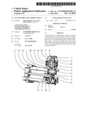
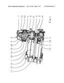
[0017]FIG. 1:
[0018]With its motor shaft 2 an electric motor 1 drives a first spur gear 3. The first spur gear 3 is in active engagement with a second spur gear 4 which, via an intermediate shaft 5, is connected in a rotationally fixed manner to a third spur gear 6. The third spur gear 6 is in active engagement with a fourth spur gear 7, which is connected in a rotationally fixed manner to a differential cage 8 of a differential 9. Vehicle wheels can be driven by a first drive output 10 and a second drive output 11. The housing of the electric drive consists of a central housing portion 12, a first covering housing portion 13 and a second covering housing portion 14. The covering housing portion 13 is arranged at one end of the central housing portion 12 and the covering housing portion 14 at the other end of the central housing portion 12. The central housing portion 12 consists of a cylindrical expanded section 15 in which the motor 1 is accommodated, and another expanded section 16 parallel to the cylindrical expanded section 15, in which the differential is accommodated. The motor shaft 2 is mounted on one side in a bearing 17 in the first covering housing portion 13 and on the other side in bearings 18 and 19, respectively in the central housing portion 12 and in the second covering housing portion 14. If there is no parking lock gear on the motor shaft 2, then the motor shaft 2 and the spur gear 3 connected integrally to it can also be mounted only in the bearings 17 in the housing portion and 18 in the central housing portion 12. Thus, the bearing 19 can be omitted. The intermediate shaft 5 is mounted on one side in a bearing 20 in the central housing portion 12 and in a bearing 21 in the second covering housing portion 14. The differential 9 is mounted in bearings 22 and 23, respectively in the central housing portion 12 and in the second covering housing portion 14. The first spur gear is arranged in the axial direction along the motor shaft between the electric motor 1 and the fourth spur gear 7.
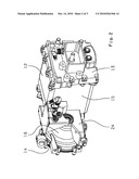
[0019]FIG. 2:
[0020]In the area of the differential 9, the central housing portion 12 has a reinforcing web 24, which connects the expanded section 16 to the cylindrical expanded section 15.
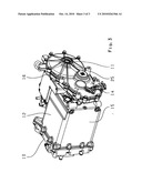
[0021]FIG. 3:
[0022]In the area of the differential 9, the second covering housing portion 14 has reinforcing ribs 25, which extend radially around the rotational axis of the second drive output 11.
[0023]Indexes
[0024]1 Electric motor
[0025]2 Motor shaft
[0026]3 First spur gear
[0027]4 Second spur gear
[0028]5 Intermediate shaft
[0029]6 Third spur gear
[0030]7 Fourth spur gear
[0031]8 Differential cage
[0032]9 Differential
[0033]10 First drive output
[0034]11 Second drive output
[0035]12 Central housing portion
[0036]13 First covering housing portion
[0037]14 Second covering housing portion
[0038]15 Cylindrical expanded section
[0039]16 Expanded section
[0040]17 Bearing
[0041]18 Bearing
[0042]19 Bearing
[0043]20 Bearing
[0044]21 Bearing
[0045]22 Bearing
[0046]23 Bearing
[0047]24 Bearing
[0048]25 Ribs
Claims:
1-10. (canceled)
11. An electric drive for a mobile vehicle with an electric motor (1) which powers first and second drive outputs (10, 11) via a spur gear mechanism (3, 4, 6, 7) and a differential (9) such that a housing encloses the differential (9), the spur gear mechanism (3, 4, 6, 7) and the electric motor (1);the housing comprising a central housing portion (12), a first covering housing portion (13) and a second covering housing portion (14) such that the central housing portion (12) being a one-piece housing comprising a cylindrical expanded section (15) accommodating the electric motor (1), the central housing portion (12) being closed at one end by the first covering housing portion (13) and having, at an opposite end, an expanded section (16) extending parallel to the cylindrical expanded section (15), in which the differential (9) and the spur gear mechanism (3, 4, 6, 7) are accommodated, and the expanded section (16) being closed by the second covering housing portion (14);the electric motor (1) comprising a motor shaft (2) such that the motor shaft (2) is mounted in the central housing portion (12), the motor shaft (2) being also mounted to rotate in the first covering housing portion (13) and in the second covering housing portion (14), and the motor shaft (2) and a first spur gear (3) being integrally connected with one another; anda parking lock gearwheel of a parking lock being arranged on the motor shaft (2).
12. The electric drive according to claim 11, wherein the spur gear mechanism comprises first, second, third and fourth spur gears, the first spur gear (3) is connected, in a rotationally fixed manner, to the motor shaft (2), the second spur gear (4) is in active engagement with the first spur gear (3) and is connected, in a rotationally fixed manner, to an intermediate shaft (5), the third spur gear (6) is also connected, in a rotationally fixed manner, to the intermediate shaft (5) and is in active engagement with the fourth spur gear (7), and the fourth spur gear (7) is connected, in a rotationally fixed manner, to the differential (9).
13. The electric drive according to claim 11, wherein an intermediate shaft (5) is mounted to rotate in both the second covering housing portion (14) and the central housing portion (12).
14. The electric drive according to claim 11, wherein the differential (9) is mounted to rotate in both the second covering housing portion (14) and the central housing portion (12).
15. The electric drive according to claim 11, wherein rotational axes of the first and the second drive outputs (10, 11) are orientated parallel to a rotational axis of the motor shaft (2).
16. The electric drive according to claim 11, wherein cooling ducts are arranged in the central housing portion (12).
17. The electric drive according to claim 12, wherein the fourth spur gear (7) is connected, by a continuous-material joint, to a differential cage (8) of the differential (9).
18. The electric drive according to claim 11, wherein a first bearing point (19) of the motor shaft (2) is arranged at one end of the motor shaft (2), a second bearing point (18) is arranged between a rotor of the electric motor (1) and a first spur gear (3), and a third bearing point (17) is arranged at an other end of the motor shaft (2).
19. The electric drive according to claim 11, wherein four main cooling ducts, arranged parallel to a rotational axis of the motor shaft (2), are located within the central housing portion (12), the four main cooling ducts are located between a round rotor of the electric motor (1) and a square outer contour of the central housing portion (12) which encloses the electric motor (1).
20. An electric drive for a mobile vehicle comprising:an electric motor (1) which powers first and second drive outputs (10, 11) via first, second, third and fourth spur gears (3, 4, 6, 7) and a differential (9),a housing encloses the differential (9), the first, the second, the third and the fourth spur gears (3, 4, 6, 7) and the motor (1), the housing comprising a central housing portion (12), a first covering housing portion (13) and a second covering housing portion (14), the central housing portion (12) comprises a cylindrical expanded section (15) accommodating the electric motor (1), a first end of the central housing portion (12) being enclosed by the first covering housing portion (13) and an opposite second end of the central housing portion (12) comprising a second expanded section (16) that expands parallel to the cylindrical expanded section (15), the differential (9) and the first, the second, the third and the fourth spur gears (3, 4, 6, 7) being accommodated within the second expanded section (16), the second expanded section (16) being enclosed by the second covering housing portion (14), the motor (1) comprising a motor shaft (2) which is rotationally supported by a bearing (17) in the first covering housing portion (13) and another bearing (19) in the second covering housing portion (14),the motor shaft (2) and the first spur gear (3) are integrally connected to one another, anda parking lock gearwheel of a parking lock is arranged on the motor shaft (2).
Description:
[0001]This application is a National Stage completion of PCT/EP2008/065641
filed Nov. 17, 2008, which claims priority from German patent application
serial no. 10 2007 055 767.3 filed Dec. 12, 2007.
FIELD OF THE INVENTION
[0002]Electric drives for mobile vehicles are used for example as stand-alone drives or as auxiliary drives for rear axles in passenger cars.
BACKGROUND OF THE INVENTION
[0003]DE 100 49 514 B4 discloses an electric drive for a rear axle of a passenger car in which, via a spur gear mechanism, an electric drive motor powers a differential whose drive outputs drive the wheels of the vehicle.
SUMMARY OF THE INVENTION
[0004]The purpose of the present invention is to provide an electric drive for a mobile vehicle, which can be constructed inexpensively and fitted simply.
[0005]This objective is achieved with an electric drive of the type concerned which also comprises the characterizing features specified in the principal claim.
[0006]The electric drive comprises an electric motor which, via a spur gear mechanism and a differential, powers two drive outputs of the differential by which, for example by means of splined shafts, the wheels of the vehicle are driven.
[0007]The electric drive has a housing which accommodates the differential, the spur gear mechanism and the electric motor. The housing consists of a central housing portion which accommodates on the one hand the electric motor and, on the other hand, essentially the spur gear mechanism and the differential. At the two ends of the central housing portion are fixed covering housing portions which enclose the central housing portion. The central housing portion has on one side a cylindrical expanded section in which the motor is arranged, and on the other side another expanded section parallel to the cylindrical expanded section in which the spur gear mechanism and the differential are arranged. This provides a height offset between the motor shaft of the electric motor and the drive outputs or the drive axles connected thereto.
[0008]In a further design form of the invention cooling ducts are formed in the central housing portion in order to cool the electric motor.
[0009]Preferably, four main cooling ducts are arranged in the central housing portion parallel to the rotational axis of the driveshaft of the electric motor, these being designed in such a manner that they occupy the structural space between the round rotor of the electric motor and the square outer contour of the central housing portion that encloses the electric motor. To ensure a flow of coolant through the housing and configure the housing so that it can be produced as a casting, at the two end sides of the central housing portion there are two connecting ducts arranged perpendicularly to the rotational axis of the driveshaft of the electric motor, each of which connects two main cooling ducts to one another and which, when they have been drilled, are closed off by sealing plugs. At one of the two ends is the coolant feed, from which coolant passes into one of the four main cooling ducts. In this main cooling duct the coolant flows through the central housing portion to the other end, then through the connecting duct into another main cooling duct and back again through the main housing portion to the first end, where it is again deflected. The coolant flows back and forth through the ducts in this way until it finally emerges through the return port, which is located on the same side as the coolant feed. Thus, the coolant follows a meandering path through the central housing portion.
[0010]In another embodiment of the invention the central housing portion has connection terminals for the power electronics for the electric motor. In addition, sealing elements can be arranged between the electric motor and the spur gear mechanism so that the electric motor is kept free from oil.
[0011]The spur gear mechanism can consist of four spur gears, one spur gear being connected in a rotationally fixed manner to the motor shaft of the electric motor and being in active engagement with a second spur gear, which is connected in a rotationally fixed manner to a third spur gear that is mounted to rotate via an intermediate shaft, such that the third spur gear is in active connection with a fourth spur gear which, finally, is connected in a rotationally fixed manner to the differential. The fourth spur gear can be connected to a differential cage of the differential by a continuous-material joint such as welding or brazing.
[0012]In a further embodiment the motor shaft is connected integrally with the first spur gear, so that the first spur gear and the motor shaft only have to be mounted at two bearing points. If in addition a parking lock is used, in which the parking lock gearwheel is arranged on the motor shaft, then the motor shaft is mounted at three bearing points, namely with one bearing at one end of the motor shaft, another bearing at the other end of the motor shaft, and a bearing between the rotor of the motor and the first spur gear.
BRIEF DESCRIPTION OF THE DRAWINGS
[0013]Other features emerge from the description of the figures, which show:
[0014]FIG. 1: Sectional view through the electric drive;
[0015]FIG. 2: Rear view of the electric drive; and
[0016]FIG. 3: Front view of the electric drive.
DETAILED DESCRIPTION OF THE PREFERRED EMBODIMENTS
[0017]FIG. 1:
[0018]With its motor shaft 2 an electric motor 1 drives a first spur gear 3. The first spur gear 3 is in active engagement with a second spur gear 4 which, via an intermediate shaft 5, is connected in a rotationally fixed manner to a third spur gear 6. The third spur gear 6 is in active engagement with a fourth spur gear 7, which is connected in a rotationally fixed manner to a differential cage 8 of a differential 9. Vehicle wheels can be driven by a first drive output 10 and a second drive output 11. The housing of the electric drive consists of a central housing portion 12, a first covering housing portion 13 and a second covering housing portion 14. The covering housing portion 13 is arranged at one end of the central housing portion 12 and the covering housing portion 14 at the other end of the central housing portion 12. The central housing portion 12 consists of a cylindrical expanded section 15 in which the motor 1 is accommodated, and another expanded section 16 parallel to the cylindrical expanded section 15, in which the differential is accommodated. The motor shaft 2 is mounted on one side in a bearing 17 in the first covering housing portion 13 and on the other side in bearings 18 and 19, respectively in the central housing portion 12 and in the second covering housing portion 14. If there is no parking lock gear on the motor shaft 2, then the motor shaft 2 and the spur gear 3 connected integrally to it can also be mounted only in the bearings 17 in the housing portion and 18 in the central housing portion 12. Thus, the bearing 19 can be omitted. The intermediate shaft 5 is mounted on one side in a bearing 20 in the central housing portion 12 and in a bearing 21 in the second covering housing portion 14. The differential 9 is mounted in bearings 22 and 23, respectively in the central housing portion 12 and in the second covering housing portion 14. The first spur gear is arranged in the axial direction along the motor shaft between the electric motor 1 and the fourth spur gear 7.
[0019]FIG. 2:
[0020]In the area of the differential 9, the central housing portion 12 has a reinforcing web 24, which connects the expanded section 16 to the cylindrical expanded section 15.
[0021]FIG. 3:
[0022]In the area of the differential 9, the second covering housing portion 14 has reinforcing ribs 25, which extend radially around the rotational axis of the second drive output 11.
[0023]Indexes
[0024]1 Electric motor
[0025]2 Motor shaft
[0026]3 First spur gear
[0027]4 Second spur gear
[0028]5 Intermediate shaft
[0029]6 Third spur gear
[0030]7 Fourth spur gear
[0031]8 Differential cage
[0032]9 Differential
[0033]10 First drive output
[0034]11 Second drive output
[0035]12 Central housing portion
[0036]13 First covering housing portion
[0037]14 Second covering housing portion
[0038]15 Cylindrical expanded section
[0039]16 Expanded section
[0040]17 Bearing
[0041]18 Bearing
[0042]19 Bearing
[0043]20 Bearing
[0044]21 Bearing
[0045]22 Bearing
[0046]23 Bearing
[0047]24 Bearing
[0048]25 Ribs
User Contributions:
Comment about this patent or add new information about this topic:
| People who visited this patent also read: | |
| Patent application number | Title |
|---|---|
| 20100259712 | Display Device with Enhanced Display Quality |
| 20100259710 | REFLECTION TYPE LIQUID CRYSTAL DISPLAY APPARATUS AND SUBSTRATE FOR REFLECTION TYPE LIQUID CRYSTAL DISPLAY |
| 20100259709 | LIQUID CRYSTAL DISPLAY DEVICE AND MANUFACTURING METHOD FOR SAME |
| 20100259707 | MOTHER PANEL, MANUFACTURING METHOD OF MOTHER PANEL AND MANUFACTURING METHOD OF LIQUID CRYSTAL DISPLAY DEVICE |
| 20100259698 | Thermally Switched Optical Filter Incorporating a Guest-Host Architecture |
Images included with this patent application:
 |  |
 |  |
| Similar patent applications: | |
| Date | Title |
|---|---|
| 2013-05-23 | Electric drive for a motor vehicle |
| 2013-07-25 | Electric drive for a motor vehicle |
| 2013-08-01 | Hybrid drive train for a motor vehicle |
| 2013-08-01 | Hybrid drive train for a motor vehicle |
| 2012-05-31 | Electrical drive apparatus for valves |
| New patent applications in this class: | |
| Date | Title |
|---|---|
| 2016-06-02 | Drive gear unit |
| 2016-05-26 | Electric axle drive for a motor vehicle |
| 2016-05-19 | Disconnecting awd driveline with torque-vectoring capabilities |
| 2016-05-19 | Electronic rear drive module with split halfshaft flange |
| 2016-05-12 | Center differential gear assembly for a drive device of a motor vehicle |
| New patent applications from these inventors: | |
| Date | Title |
|---|---|
| 2010-11-11 | Electric drive |
| Top Inventors for class "Planetary gear transmission systems or components" | |
| Rank | Inventor's name |
|---|---|
| 1 | James M. Hart |
| 2 | Scott H. Wittkopp |
| 3 | Andrew W. Phillips |
| 4 | Clinton E. Carey |
| 5 | Andrew W. Phillips |