Patent application title: Tub for washing machine or washer-drier
Inventors:
Stefano Mancini (Jesi (an), IT)
Gianfranco Bacelli (Jesi (an), IT)
IPC8 Class: AD06F2100FI
USPC Class:
68139
Class name: Textiles: fluid treating apparatus machines tumbling
Publication date: 2010-07-15
Patent application number: 20100175433
or washer-drier has a back and a front adapted
to be mutually fixed to house a rotary drum where laundry is loaded. The
front of the tub defines a loading mouth to provide access to the drum.
The front of the tub has at least one stiffening structure, integrally
obtained with the front, and adapted to avoid the deformation of the
front of the tub and consequent ovalization of the loading mouth.Claims:
1) Tub for washing machine or washer-drier comprising a back (1) and a
front (2) adapted to be mutually fixed to house a rotary drum where
laundry is loaded,said front (2) of the tub comprising a peripheral
cylindrical band (20) that is joined with a front annular wall (21) by
means of a circular connection section (22),said front wall (21) defining
a loading mouth (4) of the tub to provide access to the drum,said front
(2) of the tub comprising at least one stiffening structure (6),
integrally obtained with the front (2), adapted to avoid the deformation
of the front (2) of the tub and consequent ovalization of the loading
mouth (4), characterised in thatsaid stiffening structure (6) has a boxed
shape comprising an arched flange (60) arranged on a plane basically
parallel to the one of the front wall (21) of the front of the tub, said
flange (60) being connected to said connection section (22) of the front
of the tub by means of a plurality of stiffening ribs (61), in such a way
that said flange (60) and connection section (22) form a double wall.
2) Tub as claimed in claim 1, characterised in that said stiffening structure (6) extends at least partially along the circumference of said circular connection section (22) of the front of the tub.
3) Tub as claimed in claim 2, characterised in that said stiffening structure (6) is not provided in the area of the circular connection section (22) of the front of the tub where a counterweight (5) is fixed.
4) Tub as claimed in claim 3, characterised in that it comprises one counterweight (5) arranged on the front (2) of the tub and one stiffening structure (6) extending for an arc of circle from 270.degree. to 300.degree. in the area of the connection section (22) not provided with counterweight (5).
5) Tub as claimed in claim 3, characterised in that it comprises two counterweights (5) arranged in diametrally opposite positions on the front (2) of the tub and two stiffening structures (6) extending for an arc of circle from 90.degree. to 120.degree. in diametrally opposite positions in the areas of the connection section (22) not provided with the two counterweights (5).
6) Tub as claimed in claim 1, characterised in that said stiffening ribs (61) are arranged along oblique planes relative to the plane of the flange (60).
7) Tub as claimed in claim 1, characterised in that the front (2) of the tub is obtained in one piece from moulding plastic materials, integrally with said stiffening structure (6).
8) Tub as claimed in claim 1, characterised in that said front (2) of the tub is made of polypropylene loaded with calcium carbonate or talcum.
9) Tub as claimed in claim 1, characterised in that said front (2) of the tub is made of polypropylene loaded with fibreglass and has thickness lower than 3 mm.Description:
[0001]The present patent application for industrial invention relates to a
tub for washing machine or washer-drier.
[0002]Though specific reference is made in the following description to a washing machine, the invention is also extended to a washer-drier.
[0003]As it is known, a washing machine comprises a tub in which a rotary drum is mounted and driven into rotation by a motor. The tub is provided with a loading mouth to introduce laundry in the drum. Counterweights are positioned in the tub to balance the centrifugal force of the drum during rotation.
[0004]During the heating of the water used for the washing cycle and in particular during spinning, the tub is deformed and, consequently, the loading mouth of the tub tends to ovalize. This phenomenon especially occurs when the counterweights fixed on the front of the tub are not arranged symmetrically relative to the axis of rotation of the drum and, moreover, it depends on the material of the tub.
[0005]In general, the front of the tub is made of plastic material (polypropylene) loaded with calcium carbonate. This material tends to deform, ovalizing the loading mouth.
[0006]This problem has been partially solved by considerably increasing the thickness of the tub or loading polypropylene with fibreglass. Nevertheless, these solutions are expensive.
[0007]As shown in FIG. 1, a plastic tub for washing machines is normally composed of a back (1) and a front (2).
[0008]The back (1) is made of a peripheral cylindrical band (10) joined with a circular bottom wall (11) generally provided with stiffening ribs (12).
[0009]The front (2) is composed of a peripheral cylindrical band (20) joined with a front annular wall (21) by means of a tapered circular connection wall (22). The front (2) is adapted to be joined with the back (1) by means of fixing means of known type.
[0010]The tub houses a drum (3) for laundry that is driven into rotation by a shaft (30) joined with the back of the drum.
[0011]The bottom wall (11) of the back of the tub is provided with an axial hole (13) that is crossed by the shaft (30) of the drum. In this way, the shaft (30) is driven into rotation by means of a belt drive actuated by a motor fixed on the side of the tub. The axis of rotation of the motor is parallel to the one of the drum.
[0012]The tub (1, 2) and drum (3) assembly, as described above, is identified as oscillating assembly and indicated with numeral (100). The oscillating assembly (100) is mounted in the case of the washing machine by means of shock-absorbing springs positioned between tub and case.
[0013]Also referring to FIG. 2, the front (2) of the tub is provided with a large circular opening (4) in coaxial position with the opening of the drum, in order to load the laundry in the drum. Said opening (4) defined by the front wall (21) of the front of the tub is defined as "loading mouth".
[0014]The fact that the laundry inside the rotating drum is arranged randomly originates the formation of an unbalanced rotational mass associated with a centrifugal force that sometimes reaches very high values.
[0015]To counterbalance the centrifugal force and avoid undesired movements of the oscillating assembly of the washing machine, which may come in contact with the fixed case and damage it, the oscillating assembly (100) must be weighed down to a total weight that normally ranges from 32 and 60 kg.
[0016]Some counterweights (normally 2, sometimes 1 or 3) made of concrete, rarely of cast iron, are anchored to the tub in order to reach said weight values. The counterweights are arranged in such a way that the total centre of gravity of the oscillating assembly (100) is on the same plane as the attachments of the shock-absorbing springs.
[0017]For the oscillating assembly (100) to be balanced, at least one of the counterweights must be fixed on the front (2) of the tub.
[0018]FIG. 2 shows a counterweight (5) fixed on the front (2) of the tub. During its action to counterweight the centrifugal force, the counterweight (5) fixed on the front (2) exerts a radial rotary force on the front (2) of the tub that tends to deform the front of the tub, ovalizing the loading mouth (4) of the tub. Said ovalization causes the reduction of the loading mouth of the tub by a few millimetres along one axis and the simultaneous elongation by a few millimetres along the other axis.
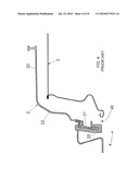
[0019]As shown in FIG. 4, in order to counterbalance said ovalization of the loading mouth of the tub, the drum (3) must be mounted with sufficient clearance inside the front (2) of the tub. In general, a space (40) lower than 3.5 mm is left in the area of the loading mouth (4) between the drum (3) and a gasket (25) arranged on the front wall (21) of the front (2) of the tub. The gasket (25) acts as connection and seal for the water between the oscillating assembly, which moves, and the door of the loading mouth that is joined with the cabinet, and is therefore fixed.
[0020]Consequently, between the edge of the drum (3) and the edge of the seal (25) of the front wall (21) of the tub, the space (40) can exceed 3.5 mm in the areas with elongation of the loading mouth (4). Therefore, if the deformation of the loading mouth (4) of the front exceeds certain values, part of the laundry can be trapped in the space (40) between the drum (3) and the front (2) with consequent damage or tear of the same laundry.
[0021]If the front counterweight (5) was shaped as a ring, with central hole coinciding with the opening of the loading mouth (4) of the tub, no deformation problems would occur because the front (2) of the tub would become rigid, being joined with the counterweight. Nevertheless, a circular counterweight can be used rarely, being more cumbersome and more expensive.
[0022]WO2008/125974 discloses a washing machine comprising a system to maintain the drum in a predefined angular position.
[0023]ES 460 773 discloses a washing machine provided with a counterweight system to stiffen the tub.
[0024]DE102 27 036 discloses a washing machine comprising a hollow container of washing liquid that encloses a drum surrounded by a support cage.
[0025]The object of the present invention is to eliminate the drawbacks of the prior art by providing a tub for washing machine adapted to reduce the deformation of the loading mouth.
[0026]Another object of the present invention is to provide such a tub for washing machine that is inexpensive and easy to make.
[0027]The said objects are achieved according to the present invention, with the features claimed in the independent claim 1.
[0028]Advantageous embodiments are disclosed in the dependent claims.
[0029]The tub for washing machine or washer-drier of the invention comprises a back and a front adapted to be mutually fixed to house a rotary drum where laundry is loaded.
[0030]The front of the tub comprises a peripheral cylindrical band that is joined with a front annular wall by means of a circular connection section. The front wall defines a loading mouth of the tub to provide access to the drum.
[0031]The front of the tub comprises at least on stiffening structure integrally obtained with said front. The stiffening structure is adapted to avoid the deformation of the front of the tub and consequent ovalization of the loading mouth.
[0032]The global advantages offered by the present solution are illustrated below.
[0033]The shape of the front of the tub provided with stiffening structure is such to maximise the structural efficacy with minimum plastic weight.
[0034]The external wall of the stiffening structure, not being in contact with the hot water contained in the tub, remains at a lower temperature and therefore maintains a higher elastic module. Such an advantage is higher in the case of a washer-drier, which needs to spin at a higher temperature.
[0035]The stiffening structure is integral to the front of the tub and therefore no additional parts are necessary, with no additional assembly operations that would increase the production cost.
[0036]The lack of deformation of the loading mouth allows for minimising clearance between drum and tub, thus preventing laundry from entering the space between drum and tub and being subjected to tear and damage.
[0037]Additional characteristics of the invention will become more evident after a detailed description that refers to a merely illustrative, not limiting, embodiment, as shown in the enclosed figures, wherein:
[0038]FIG. 1 is an exploded perspective view of an oscillating assembly for washing machine according to the prior art composed of tub and drum;
[0039]FIG. 2 is a perspective view of an oscillating assembly according to the prior art assembled and showing a counterweight mounted on the front of the tub;
[0040]FIG. 3 is a front view of a washing machine according to the prior art;
[0041]FIG. 4 is a partially interrupted cross-sectional view along plane IV-IV of FIG. 3.
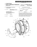
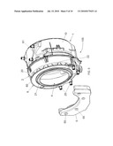
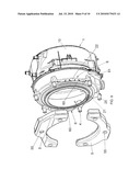
[0042]FIG. 5 is a perspective view of an oscillating assembly according to the present invention with an exploded view of one counterweight;
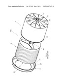
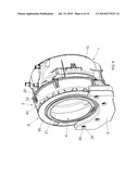
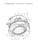
[0043]FIG. 6 is a perspective view of the oscillating assembly of FIG. 4 assembled;
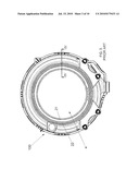
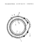
[0044]FIG. 7 is a front view of the oscillating assembly of FIG. 5;
[0045]FIG. 8 is a partially interrupted cross-sectional view along plane VIII-VIII of FIG. 7;
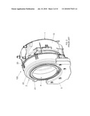
[0046]FIG. 9 is a perspective view of an oscillating assembly according to the present invention with an exploded view of two counterweights; and
[0047]FIG. 10 is a perspective view of the oscillating assembly of FIG. 9 assembled;
[0048]In the following description elements identical or corresponding to the ones described above are indicated with the same numerals, omitting a detailed description.
[0049]Referring to FIGS. 5-8, the tub of the invention comprises a front (2) provided with stiffening structure (6) integrally obtained on the front (2). The stiffening structure (6) is arranged on the connection section (22) of the front (2) of the tub, in such a way that it is at least partially around the front wall (21) of the front of the tub that defines the loading mouth (4) of the tub.
[0050]The stiffening structure (6) comprises a flange (60) composed of an arched plate arranged on a basically parallel plane to the one of the front wall (21) of the front of the tub. The flange (60) is connected to the connection section (22) of the front of the tub by means of a plurality of stiffening ribs (61). The stiffening ribs (61) are preferably arranged according to oblique planes relative to the plane of the flange (60) to oppose the radial deformation of the loading mouth (4).
[0051]The stiffening structure (6) has a boxed shape and the flange (60) and connection section (22) of the front of the tub form a double wall stiffened by the stiffening ribs (61).
[0052]The stiffening structure (6) is obtained in one piece with the front (2) of the tub from moulding inexpensive plastic materials, such as polypropylene loaded with calcium carbonate or talcum. Polypropylene can be loaded with a more expensive material, such as fibreglass. In this case it is possible to save on the quantity of material. As a matter of fact, because of the stiffening structure (6), the front (2) of the tub can be realised with thickness lower than 3 mm.
[0053]Because of its geometrical shape, the stiffening structure (6) can efficaciously oppose the deformation of the loading mouth (4) of the tub, minimising its ovalization. Consequently, the drum (3) can be arranged inside the drum (2) with minimum clearance in the area of the loading mouth (4), for instance with space lower than 3 mm, between the edge of the drum (3) and the gasket (25) of the front of the tub. Two advantages are offered by this solution: it prevents laundry from falling in the space between drum and front of the tub and maximises the opening of the drum for inserting the laundry, the latter being very appreciated by the user, especially in case of especially cumbersome laundry.
[0054]FIGS. 4 and 5 show an example of tub with installation of only one counterweight (5). To that purpose, the front (2) of the tub is provided with attachments (25) inserted in corresponding holes (55) of the counterweight.
[0055]The counterweight (5) maintains the same distance between the attachments (25) of the front of the tub, acting as reduction element of the deformation of the loading mouth in the area with the attachments (25).
[0056]Consequently, it is not necessary for the stiffening section (6) to extend also in the area of the front of the tub with the counterweight (5).
[0057]Therefore, in case of one counterweight (5), which is usually provided with arc of circle profile with 60°-90° angle, a single stiffening section (6) can be provided, extending also on the connection section (22) with an angle of 270°-300°.
[0058]FIGS. 9 and 10 illustrate an embodiment of a tub with two counterweights (5) installed in diametrally opposite positions. In such a case two stiffening sections (6) are provided, extending on the connection section (22), in diametrally opposite positions. Each stiffening section (6) has an arched shaped with angle of 90°-120°.
[0059]Numerous variations and modifications can be made to the present embodiment of the invention by an expert of the field, while still falling within the scope of the invention as claimed in the enclosed claims.
Claims:
1) Tub for washing machine or washer-drier comprising a back (1) and a
front (2) adapted to be mutually fixed to house a rotary drum where
laundry is loaded,said front (2) of the tub comprising a peripheral
cylindrical band (20) that is joined with a front annular wall (21) by
means of a circular connection section (22),said front wall (21) defining
a loading mouth (4) of the tub to provide access to the drum,said front
(2) of the tub comprising at least one stiffening structure (6),
integrally obtained with the front (2), adapted to avoid the deformation
of the front (2) of the tub and consequent ovalization of the loading
mouth (4), characterised in thatsaid stiffening structure (6) has a boxed
shape comprising an arched flange (60) arranged on a plane basically
parallel to the one of the front wall (21) of the front of the tub, said
flange (60) being connected to said connection section (22) of the front
of the tub by means of a plurality of stiffening ribs (61), in such a way
that said flange (60) and connection section (22) form a double wall.
2) Tub as claimed in claim 1, characterised in that said stiffening structure (6) extends at least partially along the circumference of said circular connection section (22) of the front of the tub.
3) Tub as claimed in claim 2, characterised in that said stiffening structure (6) is not provided in the area of the circular connection section (22) of the front of the tub where a counterweight (5) is fixed.
4) Tub as claimed in claim 3, characterised in that it comprises one counterweight (5) arranged on the front (2) of the tub and one stiffening structure (6) extending for an arc of circle from 270.degree. to 300.degree. in the area of the connection section (22) not provided with counterweight (5).
5) Tub as claimed in claim 3, characterised in that it comprises two counterweights (5) arranged in diametrally opposite positions on the front (2) of the tub and two stiffening structures (6) extending for an arc of circle from 90.degree. to 120.degree. in diametrally opposite positions in the areas of the connection section (22) not provided with the two counterweights (5).
6) Tub as claimed in claim 1, characterised in that said stiffening ribs (61) are arranged along oblique planes relative to the plane of the flange (60).
7) Tub as claimed in claim 1, characterised in that the front (2) of the tub is obtained in one piece from moulding plastic materials, integrally with said stiffening structure (6).
8) Tub as claimed in claim 1, characterised in that said front (2) of the tub is made of polypropylene loaded with calcium carbonate or talcum.
9) Tub as claimed in claim 1, characterised in that said front (2) of the tub is made of polypropylene loaded with fibreglass and has thickness lower than 3 mm.
Description:
[0001]The present patent application for industrial invention relates to a
tub for washing machine or washer-drier.
[0002]Though specific reference is made in the following description to a washing machine, the invention is also extended to a washer-drier.
[0003]As it is known, a washing machine comprises a tub in which a rotary drum is mounted and driven into rotation by a motor. The tub is provided with a loading mouth to introduce laundry in the drum. Counterweights are positioned in the tub to balance the centrifugal force of the drum during rotation.
[0004]During the heating of the water used for the washing cycle and in particular during spinning, the tub is deformed and, consequently, the loading mouth of the tub tends to ovalize. This phenomenon especially occurs when the counterweights fixed on the front of the tub are not arranged symmetrically relative to the axis of rotation of the drum and, moreover, it depends on the material of the tub.
[0005]In general, the front of the tub is made of plastic material (polypropylene) loaded with calcium carbonate. This material tends to deform, ovalizing the loading mouth.
[0006]This problem has been partially solved by considerably increasing the thickness of the tub or loading polypropylene with fibreglass. Nevertheless, these solutions are expensive.
[0007]As shown in FIG. 1, a plastic tub for washing machines is normally composed of a back (1) and a front (2).
[0008]The back (1) is made of a peripheral cylindrical band (10) joined with a circular bottom wall (11) generally provided with stiffening ribs (12).
[0009]The front (2) is composed of a peripheral cylindrical band (20) joined with a front annular wall (21) by means of a tapered circular connection wall (22). The front (2) is adapted to be joined with the back (1) by means of fixing means of known type.
[0010]The tub houses a drum (3) for laundry that is driven into rotation by a shaft (30) joined with the back of the drum.
[0011]The bottom wall (11) of the back of the tub is provided with an axial hole (13) that is crossed by the shaft (30) of the drum. In this way, the shaft (30) is driven into rotation by means of a belt drive actuated by a motor fixed on the side of the tub. The axis of rotation of the motor is parallel to the one of the drum.
[0012]The tub (1, 2) and drum (3) assembly, as described above, is identified as oscillating assembly and indicated with numeral (100). The oscillating assembly (100) is mounted in the case of the washing machine by means of shock-absorbing springs positioned between tub and case.
[0013]Also referring to FIG. 2, the front (2) of the tub is provided with a large circular opening (4) in coaxial position with the opening of the drum, in order to load the laundry in the drum. Said opening (4) defined by the front wall (21) of the front of the tub is defined as "loading mouth".
[0014]The fact that the laundry inside the rotating drum is arranged randomly originates the formation of an unbalanced rotational mass associated with a centrifugal force that sometimes reaches very high values.
[0015]To counterbalance the centrifugal force and avoid undesired movements of the oscillating assembly of the washing machine, which may come in contact with the fixed case and damage it, the oscillating assembly (100) must be weighed down to a total weight that normally ranges from 32 and 60 kg.
[0016]Some counterweights (normally 2, sometimes 1 or 3) made of concrete, rarely of cast iron, are anchored to the tub in order to reach said weight values. The counterweights are arranged in such a way that the total centre of gravity of the oscillating assembly (100) is on the same plane as the attachments of the shock-absorbing springs.
[0017]For the oscillating assembly (100) to be balanced, at least one of the counterweights must be fixed on the front (2) of the tub.
[0018]FIG. 2 shows a counterweight (5) fixed on the front (2) of the tub. During its action to counterweight the centrifugal force, the counterweight (5) fixed on the front (2) exerts a radial rotary force on the front (2) of the tub that tends to deform the front of the tub, ovalizing the loading mouth (4) of the tub. Said ovalization causes the reduction of the loading mouth of the tub by a few millimetres along one axis and the simultaneous elongation by a few millimetres along the other axis.
[0019]As shown in FIG. 4, in order to counterbalance said ovalization of the loading mouth of the tub, the drum (3) must be mounted with sufficient clearance inside the front (2) of the tub. In general, a space (40) lower than 3.5 mm is left in the area of the loading mouth (4) between the drum (3) and a gasket (25) arranged on the front wall (21) of the front (2) of the tub. The gasket (25) acts as connection and seal for the water between the oscillating assembly, which moves, and the door of the loading mouth that is joined with the cabinet, and is therefore fixed.
[0020]Consequently, between the edge of the drum (3) and the edge of the seal (25) of the front wall (21) of the tub, the space (40) can exceed 3.5 mm in the areas with elongation of the loading mouth (4). Therefore, if the deformation of the loading mouth (4) of the front exceeds certain values, part of the laundry can be trapped in the space (40) between the drum (3) and the front (2) with consequent damage or tear of the same laundry.
[0021]If the front counterweight (5) was shaped as a ring, with central hole coinciding with the opening of the loading mouth (4) of the tub, no deformation problems would occur because the front (2) of the tub would become rigid, being joined with the counterweight. Nevertheless, a circular counterweight can be used rarely, being more cumbersome and more expensive.
[0022]WO2008/125974 discloses a washing machine comprising a system to maintain the drum in a predefined angular position.
[0023]ES 460 773 discloses a washing machine provided with a counterweight system to stiffen the tub.
[0024]DE102 27 036 discloses a washing machine comprising a hollow container of washing liquid that encloses a drum surrounded by a support cage.
[0025]The object of the present invention is to eliminate the drawbacks of the prior art by providing a tub for washing machine adapted to reduce the deformation of the loading mouth.
[0026]Another object of the present invention is to provide such a tub for washing machine that is inexpensive and easy to make.
[0027]The said objects are achieved according to the present invention, with the features claimed in the independent claim 1.
[0028]Advantageous embodiments are disclosed in the dependent claims.
[0029]The tub for washing machine or washer-drier of the invention comprises a back and a front adapted to be mutually fixed to house a rotary drum where laundry is loaded.
[0030]The front of the tub comprises a peripheral cylindrical band that is joined with a front annular wall by means of a circular connection section. The front wall defines a loading mouth of the tub to provide access to the drum.
[0031]The front of the tub comprises at least on stiffening structure integrally obtained with said front. The stiffening structure is adapted to avoid the deformation of the front of the tub and consequent ovalization of the loading mouth.
[0032]The global advantages offered by the present solution are illustrated below.
[0033]The shape of the front of the tub provided with stiffening structure is such to maximise the structural efficacy with minimum plastic weight.
[0034]The external wall of the stiffening structure, not being in contact with the hot water contained in the tub, remains at a lower temperature and therefore maintains a higher elastic module. Such an advantage is higher in the case of a washer-drier, which needs to spin at a higher temperature.
[0035]The stiffening structure is integral to the front of the tub and therefore no additional parts are necessary, with no additional assembly operations that would increase the production cost.
[0036]The lack of deformation of the loading mouth allows for minimising clearance between drum and tub, thus preventing laundry from entering the space between drum and tub and being subjected to tear and damage.
[0037]Additional characteristics of the invention will become more evident after a detailed description that refers to a merely illustrative, not limiting, embodiment, as shown in the enclosed figures, wherein:
[0038]FIG. 1 is an exploded perspective view of an oscillating assembly for washing machine according to the prior art composed of tub and drum;
[0039]FIG. 2 is a perspective view of an oscillating assembly according to the prior art assembled and showing a counterweight mounted on the front of the tub;
[0040]FIG. 3 is a front view of a washing machine according to the prior art;
[0041]FIG. 4 is a partially interrupted cross-sectional view along plane IV-IV of FIG. 3.
[0042]FIG. 5 is a perspective view of an oscillating assembly according to the present invention with an exploded view of one counterweight;
[0043]FIG. 6 is a perspective view of the oscillating assembly of FIG. 4 assembled;
[0044]FIG. 7 is a front view of the oscillating assembly of FIG. 5;
[0045]FIG. 8 is a partially interrupted cross-sectional view along plane VIII-VIII of FIG. 7;
[0046]FIG. 9 is a perspective view of an oscillating assembly according to the present invention with an exploded view of two counterweights; and
[0047]FIG. 10 is a perspective view of the oscillating assembly of FIG. 9 assembled;
[0048]In the following description elements identical or corresponding to the ones described above are indicated with the same numerals, omitting a detailed description.
[0049]Referring to FIGS. 5-8, the tub of the invention comprises a front (2) provided with stiffening structure (6) integrally obtained on the front (2). The stiffening structure (6) is arranged on the connection section (22) of the front (2) of the tub, in such a way that it is at least partially around the front wall (21) of the front of the tub that defines the loading mouth (4) of the tub.
[0050]The stiffening structure (6) comprises a flange (60) composed of an arched plate arranged on a basically parallel plane to the one of the front wall (21) of the front of the tub. The flange (60) is connected to the connection section (22) of the front of the tub by means of a plurality of stiffening ribs (61). The stiffening ribs (61) are preferably arranged according to oblique planes relative to the plane of the flange (60) to oppose the radial deformation of the loading mouth (4).
[0051]The stiffening structure (6) has a boxed shape and the flange (60) and connection section (22) of the front of the tub form a double wall stiffened by the stiffening ribs (61).
[0052]The stiffening structure (6) is obtained in one piece with the front (2) of the tub from moulding inexpensive plastic materials, such as polypropylene loaded with calcium carbonate or talcum. Polypropylene can be loaded with a more expensive material, such as fibreglass. In this case it is possible to save on the quantity of material. As a matter of fact, because of the stiffening structure (6), the front (2) of the tub can be realised with thickness lower than 3 mm.
[0053]Because of its geometrical shape, the stiffening structure (6) can efficaciously oppose the deformation of the loading mouth (4) of the tub, minimising its ovalization. Consequently, the drum (3) can be arranged inside the drum (2) with minimum clearance in the area of the loading mouth (4), for instance with space lower than 3 mm, between the edge of the drum (3) and the gasket (25) of the front of the tub. Two advantages are offered by this solution: it prevents laundry from falling in the space between drum and front of the tub and maximises the opening of the drum for inserting the laundry, the latter being very appreciated by the user, especially in case of especially cumbersome laundry.
[0054]FIGS. 4 and 5 show an example of tub with installation of only one counterweight (5). To that purpose, the front (2) of the tub is provided with attachments (25) inserted in corresponding holes (55) of the counterweight.
[0055]The counterweight (5) maintains the same distance between the attachments (25) of the front of the tub, acting as reduction element of the deformation of the loading mouth in the area with the attachments (25).
[0056]Consequently, it is not necessary for the stiffening section (6) to extend also in the area of the front of the tub with the counterweight (5).
[0057]Therefore, in case of one counterweight (5), which is usually provided with arc of circle profile with 60°-90° angle, a single stiffening section (6) can be provided, extending also on the connection section (22) with an angle of 270°-300°.
[0058]FIGS. 9 and 10 illustrate an embodiment of a tub with two counterweights (5) installed in diametrally opposite positions. In such a case two stiffening sections (6) are provided, extending on the connection section (22), in diametrally opposite positions. Each stiffening section (6) has an arched shaped with angle of 90°-120°.
[0059]Numerous variations and modifications can be made to the present embodiment of the invention by an expert of the field, while still falling within the scope of the invention as claimed in the enclosed claims.
User Contributions:
Comment about this patent or add new information about this topic:
Images included with this patent application:
 |  |
 |  |
 |  |
 |  |
 |  |
 |
| Similar patent applications: | |
| Date | Title |
|---|---|
| 2013-01-31 | Motor usable with washing machine and washing machine having the same |
| 2010-02-18 | Washing machine to wash laundry with bubbles |
| 2012-12-06 | Washing machine improving washing efficiency |
| 2013-01-31 | Tub and washing machine having the same |
| 2009-07-02 | Tub for washing machine |
| New patent applications in this class: | |
| Date | Title |
|---|---|
| 2016-02-18 | Power generating device and apparatus having the same |
| 2016-02-18 | Washing machine pump |
| 2016-02-11 | Washing machine and control method of same |
| 2015-12-03 | Laundry treating appliance with dynamic balancer |
| 2015-10-15 | Washing machine |
| New patent applications from these inventors: | |
| Date | Title |
|---|---|
| Top Inventors for class "Textiles: fluid treating apparatus" | |
| Rank | Inventor's name |
|---|---|
| 1 | Doo Young Ryu |
| 2 | Ig Geun Kwon |
| 3 | Sang Yeon Pyo |
| 4 | Dong Won Kim |
| 5 | Jae Ryong Park |