Patent application title: SHRINKING COIL WITH DIRECT TOOL COOLING
Inventors:
Franz Haimer (Igenhausen, DE)
Assignees:
FRANZ HAIMER MASCHINENBAU KG
IPC8 Class: AH05B610FI
USPC Class:
219635
Class name: Electric heating inductive heating specific heating application
Publication date: 2010-06-03
Patent application number: 20100133262
ates to a device for tensioning or de-tensioning
tools, having a tool shaft in a tool chuck which has a sheath section
open on the free end thereof and which is made of electrically conductive
material, for receiving the tool shaft in a friction connection, having
an induction coil which surrounds the sheath section of the tool chuck,
to which preferably high-frequency alternating current can be applied,
and which is designed as a ring or cylinder coil, wherein the device has
at least one channel running between the inner peripheral surface of the
induction coil and the sheath section of the tool chuck, through which
flows a cooling agent which cools the sheath section of the tool chuck.Claims:
1. A device for clamping and/or unclamping tools, comprising a tool shaft,
in a tool chuck, which comprises a sleeve section, which is open at its
free end and which is made of electrically conductive material for
friction locked receiving of the tool shaft, with an induction coil,
comprising the sleeve section of the tool chuck, which induction coil can
be loaded with a current and which is configured as an annular coil or a
cylindrical coil, wherein the device comprises at least one channel,
extending between the inner circumferential surface of the induction coil
and the sleeve section of the tool chuck, through which channel a coolant
is flowed, which cools the sleeve section of the tool chuck.
2. A device according to claim 1, wherein the channel is configured and routed, so that the coolant directly contacts the sleeve section at least in sections, wherein the sleeve section forms a wall of the channel in sections.
3. A device according to claim 2, wherein a seal is disposed at the opening, through which the sleeve section is inserted into the coil or removed there from, which seal seals the section of the sleeve section, which forms a wall of the channel, against the wall of the channel, connecting with said sleeve section, when the sleeve section is held in the coil.
4. A device according to claim 2, wherein a field concentrator, through which the magnetic field is inducted into the free face of the sleeve section, contacts the face of the sleeve section so it seals, so that substantially no coolant can exit through the contact surface between the field concentrator and the face of the sleeve section.
5. A device according to claim 1, wherein the channel is configured and routed, so that the coolant comes into heat transferring contact with the sleeve section with a seal placed there between, which does not substantially impede heat transfer.
6. A device according to claim 1, wherein the channel is configured and routed, so that the coolant at least over a certain distance cools a substantially locally fixated additional coolant, which comes into heat conducting contact with the sleeve section, either directly, or at the most with a seal not substantially restricting heat transfer.
7. A device according to claim 1, wherein the channel, at least with the tool chuck inserted, forms a substantially hydraulically or pneumatically closed path between a coolant feed conduit and a coolant scavenging conduit.
8. A device according to claim 1, wherein a temperature sensor is disposed in the return of the cooling medium in order to monitor the cooling process.
9. A device according to claim 5, wherein the channel comprises a flexible seal membrane at least in sections, in order to form a hydraulically or pneumatically completely closed path, which seal membrane contacts and conforms to the surface of the sleeve section to be cooled.
10. A device according to claim 5, wherein the channel for forming a hydraulically or pneumatically completely closed path comprises a coolant pressure resistant heat exchanger, which in turn cools another coolant which is held at least in sections between the heat exchanger and a flexible seal membrane, and which causes a close conformal contact of the flexible seal membrane with the surface of the sleeve section to be cooled.
11. A device according to claim 5, wherein the seal membrane or the seal bellows is made of a high temperature resistant elastomer.
12. A device according to claim 1, wherein the induction coil is encased, so that it is completely coolant- or coolant vapor tight.
13. A device according to claim 12, wherein the molded encasement of the induction coil is protected by an at least local shield, which is made of a suitable material, which is neither electrically--nor magnetically conductive, against an excessively heat transferring contact with the sleeve section.
14. A device according to claim 12, wherein an opposite electrode is disposed in the coolant cycle, by means of which an unwanted current flow between the coil and the coolant can be detected.
15. A device according to claim 1, wherein the outer circumferential surface and the outer face of the induction coil are enclosed by a housing, which forms other sections of the coolant routing channel and which supports the connections for the coolant feed conduit and for the coolant scavenging conduit.
16. A device according to claim 15, wherein the coil is inserted along its main axis into a respective recess of the housing, and sealed at the housing against coolant exit into the gap between the coil and the housing.
17. A device according to claim 1, wherein the coolant and possible coolant vapors are extracted through the coolant scavenging conduit.
18. A device according to claim 1, wherein the unit made of coil and housing forms an exchangeable module, and each shrink device comprises plural such modules, wherein the particular modules differ through their inner coil diameter, this means through the outer diameter range of the sleeve sections of the tool chucks to be operated.
19. A device according to claim 1, wherein the coolant feed conduit and the coolant scavenging conduit can be coupled and decoupled by quick couplings, which can be operated without tools.
20. A device according to claim 1, wherein the channel comprises a jet body, which is impacted on the one side by the coolant feed conduit, and which comprises fine bore holes, through which the coolant is jetted into a cavity formed by the jet body and by the sleeve section, wherein the cavity is connected to the coolant scavenging conduit, which scavenges the coolant jetted into the cavity and also the coolant vapor created there.
21. A device according to claim 1, wherein the coolant simultaneously also cools the induction coil to a more than insignificant extent.
22. A device according to claim 1, wherein the channel is configured, so that the coolant flows in a spiral--or racetrack pattern along the coil, so that the heat exchange between the coil and the coolant is intensified.
23. A device for cooling a hot tool chuck, comprising an outer sleeve or collar which can be pushed over the sleeve section to be cooled, wherein the outer sleeve or collar comprises a channel, extending at its inside at least between the inside of the outer sleeve/collar and the sleeve section of the tool chuck, through which channel a coolant is flowed, which cools the sleeve section of the tool chuck.Description:
CROSS-REFERENCE TO RELATED PATENT APPLICATIONS
[0001]This is a continuation of International Patent Application No. PCT/EP2008/003223, entitled "Shrinking Coil with Direct Tool Cooling," filed on 22 Apr. 2008, which claims priority to DE 20 2007 007 837.4, filed on 1 Jun. 2007, both of which are incorporated by reference herein in their entireties.
BACKGROUND
[0002]The invention relates to a device for clamping and/or unclamping of tools, comprising a tool shaft in a tool chuck by means of a shrink connection between the tool chuck and the tool shaft.
[0003]A device of said type is known e.g. from the German Patent Application DE 103 48 880 A1, which describes the basic configuration and the function of such a device in detail, and which is therefore incorporated by reference into the present patent application.
[0004]A general problem of such devices is cooling the tool chuck back down, which has been heated up for clamping or unclamping. This is on the one hand, because the time required for cooling tends to increase the overall time required for the tool change until an operable tool is provided again, on the other hand, because manual removal of tool clamping chucks, which are still hot, is associated with a substantial accident risk.
[0005]Therefore, it has already been considered to provide cooling by means of solid cooling bodies, this means by bringing the tool chuck in close contact with another solid body with good heat conducting properties, into which the heat stored in the tool chuck is transferred quickly.
[0006]However, such cooling is difficult to accomplish in practical applications. A close surface contact between the chuck and the cooling body has to exist, since heat can only be transferred efficiently that way. The tool chucks or their sleeve sections performing the actual clamping have to have a conical outer contour, since only this way, a sufficiently close contact can be established. With cylindrical chucks, establishing the required surface contact is difficult. In any case, the cooling body and the chuck have to be adjusted to one another. A real integration of the cooling body into the coil unit is not possible. Heating and cooling thus has to be performed at different places, consequently hot chucks need to be handled. It is very difficult to automate such cooling completely or at least to a high extent.
[0007]In practical applications, therefore typically, the cooling is performed with water, so that the chuck is removed from the clamping device and submerged in water or showered with water. Also this has significant disadvantages, since in turn, integration into the coil unit is hardly possible, but again the hot chuck has to be handled. Even more so with such cooling, a substantial or complete automation is hardly possible. Furthermore, the whole chuck becomes wet. It has to be cautiously dried subsequently, which is complex. Overall, also for such cooling, a long drying cycle is required.
SUMMARY
[0008]Accordingly, it is the object of the invention to improve a clamping or unclamping device of said type, so that the hot chuck is cooled in place, this means without having to pull the hot chuck out of the coil.
[0009]This object is accomplished by devices according to patent claim 1 and according to the independent claim. The advantages and the effect in particular also of the particular embodiments provided by the dependent claims can be derived from the subsequent description of the figures for the embodiments.
DRAWINGS
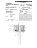
[0010]FIG. 1 shows a first embodiment a device for clamping and/or unclamping tools.
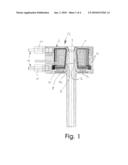
[0011]FIG. 2 shows an alternative embodiment of the device for clamping and/or unclamping tools having a sleeve portion that does not come into direct contact with the coolant.
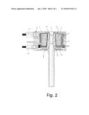
[0012]FIG. 3 shows another embodiment of the device for clamping and/or unclamping tools that includes an additional a jet body inserted into the cooling channel.
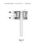
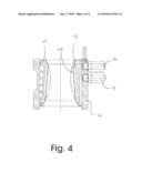
[0013]FIG. 4 shows another embodiment of the device for clamping and/or unclamping tools having a removable cooling device.
DETAILED DESCRIPTION
[0014]FIG. 1 shows a first embodiment of the invention. The induction coil 1 forms a magnetic loop in combination with the field concentrator 3, the sleeve section 2 of the tool chuck and the field conductor devices 4, which magnetic loop heats the sleeve section 2 of the tool chuck.
[0015]The sleeve section 2 thus forms a cooling channel 5 together with the coil housing 6 surrounding the coil 1. Said cooling channel is e.g. flowed through by water, which is typically mixed with corrosion inhibitors. Also, any other suitable fluid can be used, e.g. a fluid like glycol or a gas or a liquefied gas. The cooling channel extends between the coolant feed conduit 10 and the coolant scavenging conduit 11. When the tool chuck is inserted, the cooling channel is at least substantially sealed relative to ambient.
[0016]A section of said cooling channel 5 extends between the inner surface of the induction coil 1, which is protected by a coolant tight encapsulation 7 and by a heat shield 8, and between the sleeve section 2. Thus, the sleeve section directly forms one of the walls of the cooling channel 5, along at least a part of said portion, which provides excellent heat transfer.
[0017]In order to implement this, a fold-over seal 14 is provided in the portion of the opening, through which the sleeve section 2 is inserted into the interior of the coil 1. Said seal is configured soft enough, so that it attaches tight to the sleeve section, as soon as it is inserted into the coil. At its upper free face, the sleeve section contacts the opposite surface of the field concentrator 3, which is configured sufficiently precise, with the necessary contact pressure. The contact is configured so that, also here, a sealing is provided, at least substantially, mainly in the sense that only few coolant drops exit during the coolant cycle, which only lasts a couple of moments, so that the sleeve section 2 or the chuck only get a little wet.
[0018]The operation of the device is illustrated here with reference to an exemplary unclamping process.
[0019]Immediately after ending the heat-up process, the shaft of the tool to be unclamped is extracted from the sleeve section 2.
[0020]Then coolant is flushed into the gap 5 through the coolant feed line 10 by means of a coolant pump or by means of the pressure of the coolant reservoir. Said coolant contacts the sleeve section and cools it within a few seconds to a temperature, which facilitates risk free handling of the chuck. Typically, already in this phase, vacuum is applied to the coolant scavenging conduit 11 in order to extract coolant vapor which may have been created. A temperature sensor in the return of the cooling medium can monitor the cooling process, this means ending the cooling process as soon as the back flowing coolant has reached a certain lower temperature limit, or as soon as its temperature doesn't change substantially any more. The end of the cooling process can be indicated acoustically or optically.
[0021]The coolant supply is stopped now. Since, now at the latest, vacuum is applied to the coolant extraction conduit 11, the coolant still disposed in the cooling channel 5 is extracted almost without residual. If the coolant supply--and scavenging conduit are configured with the three-way valves, which are not shown here, now compressed air or similar is blown through the cooling channel 5 in order to dry the wetted surface of the sleeve section. Then, the sleeve section is pulled out of the coil and the next cycle can begin by inserting the next sleeve section into the coil so it seals.
[0022]It is important that at no point in time, there is a risk of burns for the user, since the hot portion of the chuck is not accessible at any point in time, but it is completely covered by the coil and by the cooling device.
[0023]It is a significant advantage of said solution that the outer contour of the sleeve section 2 can vary within certain limits, since due to the direct wetting; no particular requirements have to be placed upon the contour of the sleeve section.
[0024]It is a relevant feature, that the induction coil 1 is completely encased through injection molding or vulcanized, so that it is reliably protected against the penetration of coolant or coolant vapor. In order to check the tightness of the encasement compound, a low voltage can be applied to the coil winding during the testing cycle. It is being measured with an opposite electrode in the coolant loop, if a current flows between coil and coolant.
[0025]Since the outer diameters of the sleeve sections of the chucks to be shrunk vary highly in practical applications, not all sleeve diameters can be shrunk with a single coil, when using the strong induction coil shown here. Thus, often not only a single coil is included in a device according to the invention, but a coil set with plural coils, which can be exchanged. Each coil advantageously forms a replaceable module together with its housing 6 forming the cooling channel 5. Said module is connected to the rest of the device through a disengagable electrical connection and through quick couplings for the coolant supply that can be operated without tools. It can be installed and removed as a complete modular unit with few manual operations, depending on which sleeve diameter is to be shrunk at the moment. Thus, the entire coolant duct remains with the respective coil, thus it is being installed and removed with it, which facilitates quick and clean handling. The machine operator thus has almost no contact with the coolant. Through the invention, it is also possible, instead of replacing the particular coils, to connect all coils of a coil set to the device, and to actuate only the particular coils when required, this means to supply power to them and to tie them into the coolant loop.
[0026]FIG. 2 shows an alternative embodiment of the invention.
[0027]The difference to the embodiment illustrated in FIG. 1 is only that the sleeve portion does not come into direct contact with the coolant, but only through a seal membrane 15, or through a seal bellows. Accordingly, also the fold-over seal 14 can be omitted, which, however, is still being used as an additional seal.
[0028]Also, in the portion of the field concentrator 3, no particular measures for sealing have to be taken anymore. Also, in this portion, the seal membrane 15 seals, which runs along here, between the coil and the field concentrator, up to the location where it is connected into the coil housing 6 with its drop shaped or bead shaped protrusion.
[0029]Differences caused by the function of the seal membrane notwithstanding, the statements made with respect to FIG. 1 apply analogously.
[0030]After heating the sleeve section, coolant is pumped through the gap between the coil and the seal membrane 15 for cooling purposes. The seal membrane expands due to the coolant pressure and comes into surface contact with the chuck (the delineation of the seal membrane 15 indicated in dashed lines in FIG. 2 would be established if no chuck or no sleeve section were inserted). The chuck is not wetted and thus does not have to be dried after the cooling process. The coolant flows into a closed loop. No seals are required, which have to contact the sleeve section closely after each cycle, so that a correct sealing against the sleeve section is accomplished, which thus entails the risk of operator errors and wear.
[0031]Thus, the cooling device to the extent of the flexibility of the seal membrane also here remains substantially independent from the contour of the sleeve section. Also here, like in FIG. 1, it holds that almost all customary chucks can be cooled, and not only such chucks which are adapted and which form an expensive "system" together with the entire device.
[0032]FIG. 3 shows another embodiment of the invention, which only differs from the embodiment of the invention shown in FIG. 1, in that an additional a jet body 17 is inserted into the portion of the cooling channel 5, which extends as shown between the inner circumferential surface of the coil 1 and the sleeve section 2. Therefore, also here, the statements made with respect to FIG. 1 hold as long as no other requirements result from the principle of the jet body.
[0033]The jet body 17 is provided with an inflow channel for the coolant on its side facing the coil winding. Furthermore, the jet body is provided with jet bore holes extending herein substantially in radial direction, through which the coolant pressure established on the side of the inflow channel is substantially relieved and which atomize or fog the coolant in turn and which let it impact the surface to be cooled of the sleeve section 2 in this condition, where the coolant can evaporate. The resulting steam or the downward running coolant or condensate are scavenged through the coolant scavenging line 11.
[0034]Said coolant body 17 has the advantage that the required coolant volume can be significantly reduced. The process can thus be easily controlled, so that the coolant mostly evaporates on the hot surface of the sleeve section 2, which is known to cause very high energy transfer, this means effective cooling at a low coolant volume. This can be particularly advantageous, where the system is not operated connected to a coolant network, but where it has to operate with a small coolant supply. Thus, the problem of coolant scavenging may be obviated, since water vapor can generally be simply released into the ambient.
[0035]As a matter of principle, it is conceivable that a membrane is also used for the embodiment illustrated in FIG. 3 as illustrated in FIG. 2. Depending on the intensity of the jetting of the membrane, there may be a very high thermal loading of the membrane 15 at times, which needs to be considered.
[0036]FIG. 4 shows another embodiment herein, however, not in the form of an integrated cooling device but in the form a separate cooling device. It is comprised of an outer sleeve or collar 20, which is pushed over the sleeve section (sleeve section not shown in FIG. 4), which is already pulled out of the induction coil.
[0037]The collar 20 is supplied with coolant through respective connections. A hollow cylindrical body, which is designated as a heat exchanger 19, and which comprises grooves, which form a cooling channel 5 together with the inner wall of the collar, is inserted or pressed into the inside of the collar 20 and sealed relative to the collar by two cord seals.
[0038]The coolant flowing through said cooling channel 5 in this embodiment, however, does not come into direct contact with the sleeve section, and is not only separated from it by the seal membrane 15 either. Instead, the heat exchange 19 is thus enveloped and sealed by the seal membrane 15, so that a pocket which is sealed on all sides is created between the heat exchanger 19 and the seal membrane 15. Said pocket is preferably filled with a gel type substance, which in turn has good heat transfer properties and which operates as an additional coolant.
[0039]It is the purpose of said substance to provide close contact with the sleeve section to be cooled. Said substance achieves said purpose by forming an "elastic cushion" in combination with the elastic seal membrane 15 enclosing it, which elastic cushion molds around the sleeve section (in FIG. 4 the contour which the inserted sleeve section assumes is drawn hatched). The contour which is assumed by the elastic cushion in unloaded condition is shown without a hatching. Furthermore, it is another object of said substance to transfer the heat of the sleeve section through the heat exchanger to the coolant flowing in a coolant channel 5.
[0040]Such a separate cooling unit has the advantage, that different than during integration, no coolant flows proximal to the current conducting components, thus no respective safety precautions have to be taken. Furthermore, they facilitate synchronous operation, this means while a chuck is still being cooled, and the next chuck in the induction coil can already be heated.
[0041]It is easy to understand that the cooling concept, which implements the separate cooling unit shown by FIG. 4, can also be used for integrated cooling devices, which is shown e.g. in FIG. 2, and for which patent protection is also applied for. Said cooling concept in which the risk of an undesired exit of coolant from the cooling channel, e.g. due to damaging the seal membrane 15 can be handled easily, can in particular be used, where a coolant is preferably used instead of water, which coolant is physiologically not without consequences, or which should not leak for other reasons either.
[0042]On the other hand, it is evident that the cooling concepts shown in FIGS. 1 through 3 can also be used for a separate cooling unit, as shown in particular in FIG. 4, for which protection is also applied for.
[0043]The drawings depicted in the figures are not only rough sketches, but they are already detailed engineering drawings. This is why all features shown in the drawings are relevant for the respective bodies. As a precautionary measure also the illustrated features are made objects of the patent claims.
REFERENCE NUMERALS AND DESIGNATIONS
[0044]1 induction coil [0045]2 sleeve section of the tool chuck [0046]3 field concentrator [0047]4 field conductor devices [0048]5 channel (cooling channel) [0049]6 housing of the induction coil [0050]7 encapsulation of the induction coil [0051]8 heat shield for encapsulating the induction coil [0052]9 coolant routing device for intensifying coil cooling [0053]10 coolant feed line [0054]11 coolant scavenging line [0055]12 quick release clutch [0056]13 exchangeable module made of coil 1 and housing 6 [0057]14 fold-over seal [0058]15 seal membrane or bellows [0059]16 cord seal [0060]17 jet body [0061]18 contact gel [0062]19 heat exchanger [0063]20 outer sleeve or collar
Claims:
1. A device for clamping and/or unclamping tools, comprising a tool shaft,
in a tool chuck, which comprises a sleeve section, which is open at its
free end and which is made of electrically conductive material for
friction locked receiving of the tool shaft, with an induction coil,
comprising the sleeve section of the tool chuck, which induction coil can
be loaded with a current and which is configured as an annular coil or a
cylindrical coil, wherein the device comprises at least one channel,
extending between the inner circumferential surface of the induction coil
and the sleeve section of the tool chuck, through which channel a coolant
is flowed, which cools the sleeve section of the tool chuck.
2. A device according to claim 1, wherein the channel is configured and routed, so that the coolant directly contacts the sleeve section at least in sections, wherein the sleeve section forms a wall of the channel in sections.
3. A device according to claim 2, wherein a seal is disposed at the opening, through which the sleeve section is inserted into the coil or removed there from, which seal seals the section of the sleeve section, which forms a wall of the channel, against the wall of the channel, connecting with said sleeve section, when the sleeve section is held in the coil.
4. A device according to claim 2, wherein a field concentrator, through which the magnetic field is inducted into the free face of the sleeve section, contacts the face of the sleeve section so it seals, so that substantially no coolant can exit through the contact surface between the field concentrator and the face of the sleeve section.
5. A device according to claim 1, wherein the channel is configured and routed, so that the coolant comes into heat transferring contact with the sleeve section with a seal placed there between, which does not substantially impede heat transfer.
6. A device according to claim 1, wherein the channel is configured and routed, so that the coolant at least over a certain distance cools a substantially locally fixated additional coolant, which comes into heat conducting contact with the sleeve section, either directly, or at the most with a seal not substantially restricting heat transfer.
7. A device according to claim 1, wherein the channel, at least with the tool chuck inserted, forms a substantially hydraulically or pneumatically closed path between a coolant feed conduit and a coolant scavenging conduit.
8. A device according to claim 1, wherein a temperature sensor is disposed in the return of the cooling medium in order to monitor the cooling process.
9. A device according to claim 5, wherein the channel comprises a flexible seal membrane at least in sections, in order to form a hydraulically or pneumatically completely closed path, which seal membrane contacts and conforms to the surface of the sleeve section to be cooled.
10. A device according to claim 5, wherein the channel for forming a hydraulically or pneumatically completely closed path comprises a coolant pressure resistant heat exchanger, which in turn cools another coolant which is held at least in sections between the heat exchanger and a flexible seal membrane, and which causes a close conformal contact of the flexible seal membrane with the surface of the sleeve section to be cooled.
11. A device according to claim 5, wherein the seal membrane or the seal bellows is made of a high temperature resistant elastomer.
12. A device according to claim 1, wherein the induction coil is encased, so that it is completely coolant- or coolant vapor tight.
13. A device according to claim 12, wherein the molded encasement of the induction coil is protected by an at least local shield, which is made of a suitable material, which is neither electrically--nor magnetically conductive, against an excessively heat transferring contact with the sleeve section.
14. A device according to claim 12, wherein an opposite electrode is disposed in the coolant cycle, by means of which an unwanted current flow between the coil and the coolant can be detected.
15. A device according to claim 1, wherein the outer circumferential surface and the outer face of the induction coil are enclosed by a housing, which forms other sections of the coolant routing channel and which supports the connections for the coolant feed conduit and for the coolant scavenging conduit.
16. A device according to claim 15, wherein the coil is inserted along its main axis into a respective recess of the housing, and sealed at the housing against coolant exit into the gap between the coil and the housing.
17. A device according to claim 1, wherein the coolant and possible coolant vapors are extracted through the coolant scavenging conduit.
18. A device according to claim 1, wherein the unit made of coil and housing forms an exchangeable module, and each shrink device comprises plural such modules, wherein the particular modules differ through their inner coil diameter, this means through the outer diameter range of the sleeve sections of the tool chucks to be operated.
19. A device according to claim 1, wherein the coolant feed conduit and the coolant scavenging conduit can be coupled and decoupled by quick couplings, which can be operated without tools.
20. A device according to claim 1, wherein the channel comprises a jet body, which is impacted on the one side by the coolant feed conduit, and which comprises fine bore holes, through which the coolant is jetted into a cavity formed by the jet body and by the sleeve section, wherein the cavity is connected to the coolant scavenging conduit, which scavenges the coolant jetted into the cavity and also the coolant vapor created there.
21. A device according to claim 1, wherein the coolant simultaneously also cools the induction coil to a more than insignificant extent.
22. A device according to claim 1, wherein the channel is configured, so that the coolant flows in a spiral--or racetrack pattern along the coil, so that the heat exchange between the coil and the coolant is intensified.
23. A device for cooling a hot tool chuck, comprising an outer sleeve or collar which can be pushed over the sleeve section to be cooled, wherein the outer sleeve or collar comprises a channel, extending at its inside at least between the inside of the outer sleeve/collar and the sleeve section of the tool chuck, through which channel a coolant is flowed, which cools the sleeve section of the tool chuck.
Description:
CROSS-REFERENCE TO RELATED PATENT APPLICATIONS
[0001]This is a continuation of International Patent Application No. PCT/EP2008/003223, entitled "Shrinking Coil with Direct Tool Cooling," filed on 22 Apr. 2008, which claims priority to DE 20 2007 007 837.4, filed on 1 Jun. 2007, both of which are incorporated by reference herein in their entireties.
BACKGROUND
[0002]The invention relates to a device for clamping and/or unclamping of tools, comprising a tool shaft in a tool chuck by means of a shrink connection between the tool chuck and the tool shaft.
[0003]A device of said type is known e.g. from the German Patent Application DE 103 48 880 A1, which describes the basic configuration and the function of such a device in detail, and which is therefore incorporated by reference into the present patent application.
[0004]A general problem of such devices is cooling the tool chuck back down, which has been heated up for clamping or unclamping. This is on the one hand, because the time required for cooling tends to increase the overall time required for the tool change until an operable tool is provided again, on the other hand, because manual removal of tool clamping chucks, which are still hot, is associated with a substantial accident risk.
[0005]Therefore, it has already been considered to provide cooling by means of solid cooling bodies, this means by bringing the tool chuck in close contact with another solid body with good heat conducting properties, into which the heat stored in the tool chuck is transferred quickly.
[0006]However, such cooling is difficult to accomplish in practical applications. A close surface contact between the chuck and the cooling body has to exist, since heat can only be transferred efficiently that way. The tool chucks or their sleeve sections performing the actual clamping have to have a conical outer contour, since only this way, a sufficiently close contact can be established. With cylindrical chucks, establishing the required surface contact is difficult. In any case, the cooling body and the chuck have to be adjusted to one another. A real integration of the cooling body into the coil unit is not possible. Heating and cooling thus has to be performed at different places, consequently hot chucks need to be handled. It is very difficult to automate such cooling completely or at least to a high extent.
[0007]In practical applications, therefore typically, the cooling is performed with water, so that the chuck is removed from the clamping device and submerged in water or showered with water. Also this has significant disadvantages, since in turn, integration into the coil unit is hardly possible, but again the hot chuck has to be handled. Even more so with such cooling, a substantial or complete automation is hardly possible. Furthermore, the whole chuck becomes wet. It has to be cautiously dried subsequently, which is complex. Overall, also for such cooling, a long drying cycle is required.
SUMMARY
[0008]Accordingly, it is the object of the invention to improve a clamping or unclamping device of said type, so that the hot chuck is cooled in place, this means without having to pull the hot chuck out of the coil.
[0009]This object is accomplished by devices according to patent claim 1 and according to the independent claim. The advantages and the effect in particular also of the particular embodiments provided by the dependent claims can be derived from the subsequent description of the figures for the embodiments.
DRAWINGS
[0010]FIG. 1 shows a first embodiment a device for clamping and/or unclamping tools.
[0011]FIG. 2 shows an alternative embodiment of the device for clamping and/or unclamping tools having a sleeve portion that does not come into direct contact with the coolant.
[0012]FIG. 3 shows another embodiment of the device for clamping and/or unclamping tools that includes an additional a jet body inserted into the cooling channel.
[0013]FIG. 4 shows another embodiment of the device for clamping and/or unclamping tools having a removable cooling device.
DETAILED DESCRIPTION
[0014]FIG. 1 shows a first embodiment of the invention. The induction coil 1 forms a magnetic loop in combination with the field concentrator 3, the sleeve section 2 of the tool chuck and the field conductor devices 4, which magnetic loop heats the sleeve section 2 of the tool chuck.
[0015]The sleeve section 2 thus forms a cooling channel 5 together with the coil housing 6 surrounding the coil 1. Said cooling channel is e.g. flowed through by water, which is typically mixed with corrosion inhibitors. Also, any other suitable fluid can be used, e.g. a fluid like glycol or a gas or a liquefied gas. The cooling channel extends between the coolant feed conduit 10 and the coolant scavenging conduit 11. When the tool chuck is inserted, the cooling channel is at least substantially sealed relative to ambient.
[0016]A section of said cooling channel 5 extends between the inner surface of the induction coil 1, which is protected by a coolant tight encapsulation 7 and by a heat shield 8, and between the sleeve section 2. Thus, the sleeve section directly forms one of the walls of the cooling channel 5, along at least a part of said portion, which provides excellent heat transfer.
[0017]In order to implement this, a fold-over seal 14 is provided in the portion of the opening, through which the sleeve section 2 is inserted into the interior of the coil 1. Said seal is configured soft enough, so that it attaches tight to the sleeve section, as soon as it is inserted into the coil. At its upper free face, the sleeve section contacts the opposite surface of the field concentrator 3, which is configured sufficiently precise, with the necessary contact pressure. The contact is configured so that, also here, a sealing is provided, at least substantially, mainly in the sense that only few coolant drops exit during the coolant cycle, which only lasts a couple of moments, so that the sleeve section 2 or the chuck only get a little wet.
[0018]The operation of the device is illustrated here with reference to an exemplary unclamping process.
[0019]Immediately after ending the heat-up process, the shaft of the tool to be unclamped is extracted from the sleeve section 2.
[0020]Then coolant is flushed into the gap 5 through the coolant feed line 10 by means of a coolant pump or by means of the pressure of the coolant reservoir. Said coolant contacts the sleeve section and cools it within a few seconds to a temperature, which facilitates risk free handling of the chuck. Typically, already in this phase, vacuum is applied to the coolant scavenging conduit 11 in order to extract coolant vapor which may have been created. A temperature sensor in the return of the cooling medium can monitor the cooling process, this means ending the cooling process as soon as the back flowing coolant has reached a certain lower temperature limit, or as soon as its temperature doesn't change substantially any more. The end of the cooling process can be indicated acoustically or optically.
[0021]The coolant supply is stopped now. Since, now at the latest, vacuum is applied to the coolant extraction conduit 11, the coolant still disposed in the cooling channel 5 is extracted almost without residual. If the coolant supply--and scavenging conduit are configured with the three-way valves, which are not shown here, now compressed air or similar is blown through the cooling channel 5 in order to dry the wetted surface of the sleeve section. Then, the sleeve section is pulled out of the coil and the next cycle can begin by inserting the next sleeve section into the coil so it seals.
[0022]It is important that at no point in time, there is a risk of burns for the user, since the hot portion of the chuck is not accessible at any point in time, but it is completely covered by the coil and by the cooling device.
[0023]It is a significant advantage of said solution that the outer contour of the sleeve section 2 can vary within certain limits, since due to the direct wetting; no particular requirements have to be placed upon the contour of the sleeve section.
[0024]It is a relevant feature, that the induction coil 1 is completely encased through injection molding or vulcanized, so that it is reliably protected against the penetration of coolant or coolant vapor. In order to check the tightness of the encasement compound, a low voltage can be applied to the coil winding during the testing cycle. It is being measured with an opposite electrode in the coolant loop, if a current flows between coil and coolant.
[0025]Since the outer diameters of the sleeve sections of the chucks to be shrunk vary highly in practical applications, not all sleeve diameters can be shrunk with a single coil, when using the strong induction coil shown here. Thus, often not only a single coil is included in a device according to the invention, but a coil set with plural coils, which can be exchanged. Each coil advantageously forms a replaceable module together with its housing 6 forming the cooling channel 5. Said module is connected to the rest of the device through a disengagable electrical connection and through quick couplings for the coolant supply that can be operated without tools. It can be installed and removed as a complete modular unit with few manual operations, depending on which sleeve diameter is to be shrunk at the moment. Thus, the entire coolant duct remains with the respective coil, thus it is being installed and removed with it, which facilitates quick and clean handling. The machine operator thus has almost no contact with the coolant. Through the invention, it is also possible, instead of replacing the particular coils, to connect all coils of a coil set to the device, and to actuate only the particular coils when required, this means to supply power to them and to tie them into the coolant loop.
[0026]FIG. 2 shows an alternative embodiment of the invention.
[0027]The difference to the embodiment illustrated in FIG. 1 is only that the sleeve portion does not come into direct contact with the coolant, but only through a seal membrane 15, or through a seal bellows. Accordingly, also the fold-over seal 14 can be omitted, which, however, is still being used as an additional seal.
[0028]Also, in the portion of the field concentrator 3, no particular measures for sealing have to be taken anymore. Also, in this portion, the seal membrane 15 seals, which runs along here, between the coil and the field concentrator, up to the location where it is connected into the coil housing 6 with its drop shaped or bead shaped protrusion.
[0029]Differences caused by the function of the seal membrane notwithstanding, the statements made with respect to FIG. 1 apply analogously.
[0030]After heating the sleeve section, coolant is pumped through the gap between the coil and the seal membrane 15 for cooling purposes. The seal membrane expands due to the coolant pressure and comes into surface contact with the chuck (the delineation of the seal membrane 15 indicated in dashed lines in FIG. 2 would be established if no chuck or no sleeve section were inserted). The chuck is not wetted and thus does not have to be dried after the cooling process. The coolant flows into a closed loop. No seals are required, which have to contact the sleeve section closely after each cycle, so that a correct sealing against the sleeve section is accomplished, which thus entails the risk of operator errors and wear.
[0031]Thus, the cooling device to the extent of the flexibility of the seal membrane also here remains substantially independent from the contour of the sleeve section. Also here, like in FIG. 1, it holds that almost all customary chucks can be cooled, and not only such chucks which are adapted and which form an expensive "system" together with the entire device.
[0032]FIG. 3 shows another embodiment of the invention, which only differs from the embodiment of the invention shown in FIG. 1, in that an additional a jet body 17 is inserted into the portion of the cooling channel 5, which extends as shown between the inner circumferential surface of the coil 1 and the sleeve section 2. Therefore, also here, the statements made with respect to FIG. 1 hold as long as no other requirements result from the principle of the jet body.
[0033]The jet body 17 is provided with an inflow channel for the coolant on its side facing the coil winding. Furthermore, the jet body is provided with jet bore holes extending herein substantially in radial direction, through which the coolant pressure established on the side of the inflow channel is substantially relieved and which atomize or fog the coolant in turn and which let it impact the surface to be cooled of the sleeve section 2 in this condition, where the coolant can evaporate. The resulting steam or the downward running coolant or condensate are scavenged through the coolant scavenging line 11.
[0034]Said coolant body 17 has the advantage that the required coolant volume can be significantly reduced. The process can thus be easily controlled, so that the coolant mostly evaporates on the hot surface of the sleeve section 2, which is known to cause very high energy transfer, this means effective cooling at a low coolant volume. This can be particularly advantageous, where the system is not operated connected to a coolant network, but where it has to operate with a small coolant supply. Thus, the problem of coolant scavenging may be obviated, since water vapor can generally be simply released into the ambient.
[0035]As a matter of principle, it is conceivable that a membrane is also used for the embodiment illustrated in FIG. 3 as illustrated in FIG. 2. Depending on the intensity of the jetting of the membrane, there may be a very high thermal loading of the membrane 15 at times, which needs to be considered.
[0036]FIG. 4 shows another embodiment herein, however, not in the form of an integrated cooling device but in the form a separate cooling device. It is comprised of an outer sleeve or collar 20, which is pushed over the sleeve section (sleeve section not shown in FIG. 4), which is already pulled out of the induction coil.
[0037]The collar 20 is supplied with coolant through respective connections. A hollow cylindrical body, which is designated as a heat exchanger 19, and which comprises grooves, which form a cooling channel 5 together with the inner wall of the collar, is inserted or pressed into the inside of the collar 20 and sealed relative to the collar by two cord seals.
[0038]The coolant flowing through said cooling channel 5 in this embodiment, however, does not come into direct contact with the sleeve section, and is not only separated from it by the seal membrane 15 either. Instead, the heat exchange 19 is thus enveloped and sealed by the seal membrane 15, so that a pocket which is sealed on all sides is created between the heat exchanger 19 and the seal membrane 15. Said pocket is preferably filled with a gel type substance, which in turn has good heat transfer properties and which operates as an additional coolant.
[0039]It is the purpose of said substance to provide close contact with the sleeve section to be cooled. Said substance achieves said purpose by forming an "elastic cushion" in combination with the elastic seal membrane 15 enclosing it, which elastic cushion molds around the sleeve section (in FIG. 4 the contour which the inserted sleeve section assumes is drawn hatched). The contour which is assumed by the elastic cushion in unloaded condition is shown without a hatching. Furthermore, it is another object of said substance to transfer the heat of the sleeve section through the heat exchanger to the coolant flowing in a coolant channel 5.
[0040]Such a separate cooling unit has the advantage, that different than during integration, no coolant flows proximal to the current conducting components, thus no respective safety precautions have to be taken. Furthermore, they facilitate synchronous operation, this means while a chuck is still being cooled, and the next chuck in the induction coil can already be heated.
[0041]It is easy to understand that the cooling concept, which implements the separate cooling unit shown by FIG. 4, can also be used for integrated cooling devices, which is shown e.g. in FIG. 2, and for which patent protection is also applied for. Said cooling concept in which the risk of an undesired exit of coolant from the cooling channel, e.g. due to damaging the seal membrane 15 can be handled easily, can in particular be used, where a coolant is preferably used instead of water, which coolant is physiologically not without consequences, or which should not leak for other reasons either.
[0042]On the other hand, it is evident that the cooling concepts shown in FIGS. 1 through 3 can also be used for a separate cooling unit, as shown in particular in FIG. 4, for which protection is also applied for.
[0043]The drawings depicted in the figures are not only rough sketches, but they are already detailed engineering drawings. This is why all features shown in the drawings are relevant for the respective bodies. As a precautionary measure also the illustrated features are made objects of the patent claims.
REFERENCE NUMERALS AND DESIGNATIONS
[0044]1 induction coil [0045]2 sleeve section of the tool chuck [0046]3 field concentrator [0047]4 field conductor devices [0048]5 channel (cooling channel) [0049]6 housing of the induction coil [0050]7 encapsulation of the induction coil [0051]8 heat shield for encapsulating the induction coil [0052]9 coolant routing device for intensifying coil cooling [0053]10 coolant feed line [0054]11 coolant scavenging line [0055]12 quick release clutch [0056]13 exchangeable module made of coil 1 and housing 6 [0057]14 fold-over seal [0058]15 seal membrane or bellows [0059]16 cord seal [0060]17 jet body [0061]18 contact gel [0062]19 heat exchanger [0063]20 outer sleeve or collar
User Contributions:
Comment about this patent or add new information about this topic:
Images included with this patent application:
 |  |
 |  |
 |
| Similar patent applications: | |
| Date | Title |
|---|---|
| 2010-04-29 | Laser machining medical devices with localized cooling |
| 2012-06-21 | Tungsten inert gas welding torch with improved liquid cooling |
| 2010-08-26 | Transparent window with an electrically heatable coating |
| 2012-06-21 | Tungsten inert gas welding torch with improved air cooled handle |
| 2008-12-25 | Heating device with adjusting electrical contact |
| New patent applications in this class: | |
| Date | Title |
|---|---|
| 2016-04-21 | Induction coil unit |
| 2015-12-03 | Method and apparatus for performing a localized post-weld heat treatment on a thin wall metallic cylinder |
| 2015-10-29 | Methods and apparatus to reduce biological carryover using induction heating |
| 2015-03-05 | Apparatus for refurbishing a gas turbine nozzle |
| 2015-01-29 | Heating coil, heat treatment apparatus, and heat treatment method for elongated workpiece |
| New patent applications from these inventors: | |
| Date | Title |
|---|---|
| 2022-09-08 | Appliance for heat treatment and method for operating the appliance |
| 2021-11-18 | Coupling element for receiving a probe tip in a probe measuring apparatus, screw insert for receiving a probe tip in a probe measuring apparatus, coupling assembly for a probe insert in a probe measuring apparatus, and probe measuring apparatus |
| 2019-09-12 | Device for adjusting the setting of and/or for measuring a tool |
| 2016-04-21 | Tool holder |
| 2016-04-07 | Tool receptacle |
| Top Inventors for class "Electric heating" | |
| Rank | Inventor's name |
|---|---|
| 1 | Steven R. Peters |
| 2 | Shou-Shan Fan |
| 3 | Chen Feng |
| 4 | Kai-Li Jiang |
| 5 | Chang-Hong Liu |