Patent application title: SURGICAL NAVIGATION
Inventors:
Ravish V. Patwardhan (Shreveport, LA, US)
Assignees:
INTERACTIVE NEUROSCIENCE CENTER, LLC
IPC8 Class: AA61B1717FI
USPC Class:
606 80
Class name: Orthopedic instrumentation orthopedic cutting instrument reamer or drill
Publication date: 2010-05-06
Patent application number: 20100114099
gation into' the brain includes establishing a
trajectory through the skull into the brain to a target, drilling a hole
in the skull using a drill (14), and verifying the trajectory of the
drilled hole during drilling using image guidance. A surgical navigation
system includes a cannulated drill, a cannulated access member (30), and
a coupling member (16) for coupling the access member to the drill and
for maintaining alignment of the cannulations in the drill and the access
member. The access member is movable relative to the coupling member such
that the access member can be secured to tissue while the coupling member
maintains the alignment of the cannulations. A surgical kit includes a
cannulated drill, a cannulated access member, a coupling member for
coupling the access member to the drill, and a probe for receipt within
the cannulated drill.Claims:
1. A method comprising:establishing a trajectory through the skull into
the brain to a target,drilling a hole in the skull using a drill,
andverifying the trajectory of the drilled hole during drilling using
image guidance.
2. The method of claim 1 wherein the image guidance is provided by a probe received by the drill.
3. The method of claim 2 wherein the probe is received in a lumen defined by the drill.
4. The method of claim 2 further comprising:placing an access member in the drilled hole, andverifying the trajectory of the access member during placement.
5. The method of claim 4 wherein the access member is placed using the drill, and the trajectory is verified using the probe received by the drill.
6. The method of claim 1 further comprising:placing an access member in the drilled hole, andverifying the trajectory of the access member during placement.
7. A system comprising:a cannulated drill,a cannulated access member, anda coupling member for coupling the access member to the drill and for maintaining alignment of the cannulations in the drill and the access member, the access member being movable relative to the coupling member such that the access member can be secured to tissue while the coupling member maintains the alignment of the cannulations.
8. The system of claim 7 further comprising a probe for receipt within the cannulated drill.
9. The system of claim 7 further comprising a drill bit.
10. A kit comprising:a cannulated drill,a cannulated access member,a coupling member for coupling the access member to the drill, anda probe for receipt within the cannulated drill.
11. The kit of claim 10 further comprising a drill bit.
12. The kit of claim 10 further comprising a medical device.
13. The kit of claim 10 further comprising a robot arm.
14. The kit of claim 11 further comprising a medical device.
15. The kit of claim 14 further comprising a robot ann.
16. The kit of claim 11 further comprising a robot arm.
17. The kit of claim 12 further comprising a robot arm.Description:
TECHNICAL FIELD
[0001]This invention relates to surgical navigation.
SUMMARY
[0002]A method of surgical navigation into the brain includes establishing a trajectory through the skull into the brain to a target, drilling a hole in the skull using a drill, and verifying the trajectory of the drilled hole during drilling using image guidance.
[0003]Embodiments of this aspect may include one or more of the following features. The image guidance is provided by a probe received by the drill. The probe is received in a lumen defined by the drill. The method includes placing an access member in the drilled hole, and verifying the trajectory of the access member during placement. The access member is placed using the drill, and the trajectory is verified using the probe received by the drill.
[0004]A surgical navigation system includes a cannulated drill, a cannulated access member, and a coupling member for coupling the access member to the drill and for maintaining alignment of the cannulations in the drill and the access member. The access member is movable relative to the coupling member such that the access member can be secured to tissue while the coupling member maintains the alignment of the cannulations.
[0005]Embodiments of this aspect may include one or more of the following features. The system includes a probe for receipt within the cannulated drill. The system includes a drill bit.
[0006]A surgical kit includes a cannulated drill, a cannulated access member, a coupling member for coupling the access member to the drill, and a probe for receipt within the cannulated drill. Embodiments of this aspect may also include a drill bit, a medical device, and/or a robot arm.
[0007]The details of one or more embodiments of the invention are set forth in the accompanying drawings and the description below. Other features, objects, and advantages of the invention will be apparent from the description and drawings, and from the claims.
DESCRIPTION OF DRAWINGS
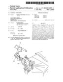
[0008]FIG. 1 is an illustration of a cannulated drill being used to place an access member in the skull under navigation guidance.
[0009]FIG. 2 is a partial cross-sectional view of the access member.
[0010]FIG. 3 is a side view of a coupling member that couples the access member to the cannulated drill.
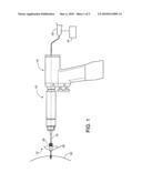
[0011]FIG. 4 shows the cannulated drill being used to drill a hole in a skull.
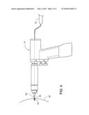
[0012]FIG. 5 shows the access member being used to position a medical device at a target site within the brain.
[0013]FIG. 6 illustrates an exemplary disposable kit containing components of the system.
[0014]FIG. 7 illustrates a robot arm supporting the cannulated drill.
DETAILED DESCRIPTION
[0015]Referring to FIG. 1, an image-guided trajectory system 10 includes an access member 12 for establishing a set trajectory to a target site, a cannulated drill 14, and a coupling member rod 16 that couples the access member 12 to the cannulated drill 14 during securement of the access member 12 to a patient's skull 20. Also shown in FIG. 1 is a probe 18, for example, a BrainLab Probe (available from BrainLab Cranial Navigation System) or an Integra Probe (available from Integra LifeSciences), received within the drill 14 and extending about half-way down the length of the drill 14. The probe 18 is coupled to an image guidance system 19, for example, a BrainLab image guidance system or an Integra image guidance system, which tracks the trajectory of the probe 18 relative to images of a patient's brain. The receipt of the probe 18 within the cannulated drill 14 during securement of the access member 12 to the skull 20 insures that the access member 12 establishes the desired trajectory to a target site.
[0016]Referring to FIG. 2, the access member 12 includes a main body 22 defining an internal lumen 24, and a clamping member 26 defining an internal lumen 28 aligned with lumen 24. The main body 22 has a distal portion 30 with a threaded region 32 that engages the skull bone to secure the access member to the skull 20. Surrounding the distal portion 30 is a depth stop 34 that sets the depth to which the access member 12 is insertable into the skull. The main body 22 has a proximal portion 36 with two outwardly extending wings 38 that can be engaged by the operator's hand and turned to thread the access member 12 into the skull.
[0017]The clamping member 26 has a threaded extension 40 that is received by the proximal portion 36 of the main body 24 and is rotatable relative to the main body 24. The clamping member 26 acts on a collet 42 located within proximal portion 36 such that rotation of the clamping member 26 causes the collet 42 to clamp onto and release the rod 16 (FIG. 3) received in the lumens 24 and 28.
[0018]Referring to FIG. 4, prior to securing the access member 12 to the skull 20, the operator uses the cannulated drill 14 to drill a pilot hole 60 in the skull 20. Using a drill bit 62 and with the probe 18 received within the drill 14, the operator drills the pilot hole 60 under image guidance such that the pilot hole 60 is aligned with a desired preplanned trajectory to a target set within the brain. Surrounding the drill bit 62 is a movable depth stop 64 that sets the depth to which the drill bit 62 is insertable into the skull.
[0019]After drilling the pilot hole, the operator replaces the drill bit 62 with the rod 16 and attached access member 12, a shown in FIG. 1. The rod 16 extends about 3.5 cm into the drill 14 and about 3.5 cm into the access member 12 to axially align the drill 14 and the access member 12. The operator places the access member 12 against the entrance to the pilot hole 60 and uses the probe 18 to align the access member 12 along the desired trajectory to the target site. The operator then loosens the collet 26 such that the access member 12 can be rotated relative to the rod 16 to advance the access member 12 into the skull 20. While the rod remains attached to the drill 14 and remains within the lumens 24, 28 during rotation of the access member 12, the rod 16 need not move, that is, is not rotated, during the advancement of the access member 12. While applying a force to the wings 38 to thread the access member 12 into the skull 20, the operator verifies the alignment of the access member 12 along the trajectory using probe 18 positioned within drill 14.
[0020]The operator then removes the drill 14 and rod 16 from the access member 12. Referring to FIG. 5, the access member 12 now establishes a set trajectory for introduction of various medical devices 70, e.g., ventriculostomy catheters, other directed catheters for convection therapy, epilepsy depth electrodes, thermocoagulation probes, lesioning probes, stereotactic needles, and ablative probes, to the target site 72. The operator need only control the depth of advancement of the medical device, which, in many cases, can be predetermined using navigation software.
[0021]To further increase the accuracy of the device placement through the access member 12, the drill 14 can directly hold the access member after securement of the access member to the skull 20, and the medical device can be passed through the drill and the access member to the target site.
[0022]A cannulated drill is available from Stryker (4200 Cordless Driver 2), and can be used with a step down chuck for holding the drill bit 62 and the rod 16.
[0023]The various components of the image-guided trajectory system 10 can be sold as kits 80 (FIG. 6), either disposable or non disposable, including one or more components of the system 10. For example, the cannulated drill 14, the access member 12, the coupling member 16, and the drill bit 62 can be packaged together for sale as a disposable kit. Alternatively, any combination of one or more of the four components can be packaged together for sale as a disposable kit, for example, just the access member 12, the coupling member 16, and the drill bit 62 can be packaged together, the access member 12 and the coupling member 16 can be packaged together, etc. The probe 18 can also be included in any of the various combinations of disposable kits described above, for example, a disposable kit can include the probe 18, drill 14, access member 12, and coupling member 16. Furthermore, one or more medical devices 70 can be included in any of the various combinations of disposable kits, including kits with the probe 18. All of the components need not be disposable. The various components can be sold as a system with the image guidance system 19.
[0024]Referring to FIG. 7, the cannulated drill 14 can be supported during use by a robot arm 82, for example, a BrainLab robot arm. The robot arm 82 can be manipulated to fix the position of the cannulated drill 14 in a selected axis. The robot arm 82 is preferably supported by a device 84, for example, a Mayfield head holder, used to fixate the head. The robot arm 82 can be included in any of the kit configurations described above.
[0025]Various modifications may be made without departing from the spirit and scope of the invention. Accordingly, other embodiments are within the scope of the following claims.
Claims:
1. A method comprising:establishing a trajectory through the skull into
the brain to a target,drilling a hole in the skull using a drill,
andverifying the trajectory of the drilled hole during drilling using
image guidance.
2. The method of claim 1 wherein the image guidance is provided by a probe received by the drill.
3. The method of claim 2 wherein the probe is received in a lumen defined by the drill.
4. The method of claim 2 further comprising:placing an access member in the drilled hole, andverifying the trajectory of the access member during placement.
5. The method of claim 4 wherein the access member is placed using the drill, and the trajectory is verified using the probe received by the drill.
6. The method of claim 1 further comprising:placing an access member in the drilled hole, andverifying the trajectory of the access member during placement.
7. A system comprising:a cannulated drill,a cannulated access member, anda coupling member for coupling the access member to the drill and for maintaining alignment of the cannulations in the drill and the access member, the access member being movable relative to the coupling member such that the access member can be secured to tissue while the coupling member maintains the alignment of the cannulations.
8. The system of claim 7 further comprising a probe for receipt within the cannulated drill.
9. The system of claim 7 further comprising a drill bit.
10. A kit comprising:a cannulated drill,a cannulated access member,a coupling member for coupling the access member to the drill, anda probe for receipt within the cannulated drill.
11. The kit of claim 10 further comprising a drill bit.
12. The kit of claim 10 further comprising a medical device.
13. The kit of claim 10 further comprising a robot arm.
14. The kit of claim 11 further comprising a medical device.
15. The kit of claim 14 further comprising a robot ann.
16. The kit of claim 11 further comprising a robot arm.
17. The kit of claim 12 further comprising a robot arm.
Description:
TECHNICAL FIELD
[0001]This invention relates to surgical navigation.
SUMMARY
[0002]A method of surgical navigation into the brain includes establishing a trajectory through the skull into the brain to a target, drilling a hole in the skull using a drill, and verifying the trajectory of the drilled hole during drilling using image guidance.
[0003]Embodiments of this aspect may include one or more of the following features. The image guidance is provided by a probe received by the drill. The probe is received in a lumen defined by the drill. The method includes placing an access member in the drilled hole, and verifying the trajectory of the access member during placement. The access member is placed using the drill, and the trajectory is verified using the probe received by the drill.
[0004]A surgical navigation system includes a cannulated drill, a cannulated access member, and a coupling member for coupling the access member to the drill and for maintaining alignment of the cannulations in the drill and the access member. The access member is movable relative to the coupling member such that the access member can be secured to tissue while the coupling member maintains the alignment of the cannulations.
[0005]Embodiments of this aspect may include one or more of the following features. The system includes a probe for receipt within the cannulated drill. The system includes a drill bit.
[0006]A surgical kit includes a cannulated drill, a cannulated access member, a coupling member for coupling the access member to the drill, and a probe for receipt within the cannulated drill. Embodiments of this aspect may also include a drill bit, a medical device, and/or a robot arm.
[0007]The details of one or more embodiments of the invention are set forth in the accompanying drawings and the description below. Other features, objects, and advantages of the invention will be apparent from the description and drawings, and from the claims.
DESCRIPTION OF DRAWINGS
[0008]FIG. 1 is an illustration of a cannulated drill being used to place an access member in the skull under navigation guidance.
[0009]FIG. 2 is a partial cross-sectional view of the access member.
[0010]FIG. 3 is a side view of a coupling member that couples the access member to the cannulated drill.
[0011]FIG. 4 shows the cannulated drill being used to drill a hole in a skull.
[0012]FIG. 5 shows the access member being used to position a medical device at a target site within the brain.
[0013]FIG. 6 illustrates an exemplary disposable kit containing components of the system.
[0014]FIG. 7 illustrates a robot arm supporting the cannulated drill.
DETAILED DESCRIPTION
[0015]Referring to FIG. 1, an image-guided trajectory system 10 includes an access member 12 for establishing a set trajectory to a target site, a cannulated drill 14, and a coupling member rod 16 that couples the access member 12 to the cannulated drill 14 during securement of the access member 12 to a patient's skull 20. Also shown in FIG. 1 is a probe 18, for example, a BrainLab Probe (available from BrainLab Cranial Navigation System) or an Integra Probe (available from Integra LifeSciences), received within the drill 14 and extending about half-way down the length of the drill 14. The probe 18 is coupled to an image guidance system 19, for example, a BrainLab image guidance system or an Integra image guidance system, which tracks the trajectory of the probe 18 relative to images of a patient's brain. The receipt of the probe 18 within the cannulated drill 14 during securement of the access member 12 to the skull 20 insures that the access member 12 establishes the desired trajectory to a target site.
[0016]Referring to FIG. 2, the access member 12 includes a main body 22 defining an internal lumen 24, and a clamping member 26 defining an internal lumen 28 aligned with lumen 24. The main body 22 has a distal portion 30 with a threaded region 32 that engages the skull bone to secure the access member to the skull 20. Surrounding the distal portion 30 is a depth stop 34 that sets the depth to which the access member 12 is insertable into the skull. The main body 22 has a proximal portion 36 with two outwardly extending wings 38 that can be engaged by the operator's hand and turned to thread the access member 12 into the skull.
[0017]The clamping member 26 has a threaded extension 40 that is received by the proximal portion 36 of the main body 24 and is rotatable relative to the main body 24. The clamping member 26 acts on a collet 42 located within proximal portion 36 such that rotation of the clamping member 26 causes the collet 42 to clamp onto and release the rod 16 (FIG. 3) received in the lumens 24 and 28.
[0018]Referring to FIG. 4, prior to securing the access member 12 to the skull 20, the operator uses the cannulated drill 14 to drill a pilot hole 60 in the skull 20. Using a drill bit 62 and with the probe 18 received within the drill 14, the operator drills the pilot hole 60 under image guidance such that the pilot hole 60 is aligned with a desired preplanned trajectory to a target set within the brain. Surrounding the drill bit 62 is a movable depth stop 64 that sets the depth to which the drill bit 62 is insertable into the skull.
[0019]After drilling the pilot hole, the operator replaces the drill bit 62 with the rod 16 and attached access member 12, a shown in FIG. 1. The rod 16 extends about 3.5 cm into the drill 14 and about 3.5 cm into the access member 12 to axially align the drill 14 and the access member 12. The operator places the access member 12 against the entrance to the pilot hole 60 and uses the probe 18 to align the access member 12 along the desired trajectory to the target site. The operator then loosens the collet 26 such that the access member 12 can be rotated relative to the rod 16 to advance the access member 12 into the skull 20. While the rod remains attached to the drill 14 and remains within the lumens 24, 28 during rotation of the access member 12, the rod 16 need not move, that is, is not rotated, during the advancement of the access member 12. While applying a force to the wings 38 to thread the access member 12 into the skull 20, the operator verifies the alignment of the access member 12 along the trajectory using probe 18 positioned within drill 14.
[0020]The operator then removes the drill 14 and rod 16 from the access member 12. Referring to FIG. 5, the access member 12 now establishes a set trajectory for introduction of various medical devices 70, e.g., ventriculostomy catheters, other directed catheters for convection therapy, epilepsy depth electrodes, thermocoagulation probes, lesioning probes, stereotactic needles, and ablative probes, to the target site 72. The operator need only control the depth of advancement of the medical device, which, in many cases, can be predetermined using navigation software.
[0021]To further increase the accuracy of the device placement through the access member 12, the drill 14 can directly hold the access member after securement of the access member to the skull 20, and the medical device can be passed through the drill and the access member to the target site.
[0022]A cannulated drill is available from Stryker (4200 Cordless Driver 2), and can be used with a step down chuck for holding the drill bit 62 and the rod 16.
[0023]The various components of the image-guided trajectory system 10 can be sold as kits 80 (FIG. 6), either disposable or non disposable, including one or more components of the system 10. For example, the cannulated drill 14, the access member 12, the coupling member 16, and the drill bit 62 can be packaged together for sale as a disposable kit. Alternatively, any combination of one or more of the four components can be packaged together for sale as a disposable kit, for example, just the access member 12, the coupling member 16, and the drill bit 62 can be packaged together, the access member 12 and the coupling member 16 can be packaged together, etc. The probe 18 can also be included in any of the various combinations of disposable kits described above, for example, a disposable kit can include the probe 18, drill 14, access member 12, and coupling member 16. Furthermore, one or more medical devices 70 can be included in any of the various combinations of disposable kits, including kits with the probe 18. All of the components need not be disposable. The various components can be sold as a system with the image guidance system 19.
[0024]Referring to FIG. 7, the cannulated drill 14 can be supported during use by a robot arm 82, for example, a BrainLab robot arm. The robot arm 82 can be manipulated to fix the position of the cannulated drill 14 in a selected axis. The robot arm 82 is preferably supported by a device 84, for example, a Mayfield head holder, used to fixate the head. The robot arm 82 can be included in any of the kit configurations described above.
[0025]Various modifications may be made without departing from the spirit and scope of the invention. Accordingly, other embodiments are within the scope of the following claims.
User Contributions:
Comment about this patent or add new information about this topic:
| People who visited this patent also read: | |
| Patent application number | Title |
|---|---|
| 20100111284 | SYNCHRONIZATION OF MULTIPLE TARGET SYSTEM DATA |
| 20100111283 | METHODS, APPARATUS AND ARTICLES OF MANUFACTURE TO DETERMINE ROUTING FOR IDENTICAL VIRTUAL PRIVATE NETWORK (VPN) NUMBERS ASSIGNED TO MULTIPLE COMPANIES |
| 20100111282 | Remote monitoring of phone calls |
| 20100111280 | GEOGRAPHICAL CALL ROUTING FOR A NON-EMERGENCY CALLING SERVICE |
| 20100111279 | Systems and Methods for Generating a Calling List For a Conference Call |
Images included with this patent application:
 |  |
 |  |
 |  |
| Similar patent applications: | |
| Date | Title |
|---|---|
| 2011-12-08 | Surgical navigational and neuromonitoring instrument |
| 2008-10-02 | Surgical method and apparatus for treating atrial fibrillation |
| 2009-11-05 | System and method for lasers in surgical applications |
| 2010-07-22 | Surgical ligation clip |
| 2011-09-15 | Narrow profile surgical ligation clip |
| New patent applications in this class: | |
| Date | Title |
|---|---|
| 2019-05-16 | Cranial perforator |
| 2018-01-25 | Angled instrument assembly |
| 2017-08-17 | Depth controllable and measurable medical driver devices and methods of use |
| 2017-08-17 | Cutting heads for intramedullary reamers |
| 2017-08-17 | Femoral orthopaedic instrument assembly for setting offset |
| New patent applications from these inventors: | |
| Date | Title |
|---|---|
| 2013-06-27 | Surgical navigation |
| 2012-12-06 | Medical devices for the detection, prevention and/or treatment of neurological disorders, and methods related thereto |
| Top Inventors for class "Surgery" | |
| Rank | Inventor's name |
|---|---|
| 1 | Lutz Biedermann |
| 2 | Roger P. Jackson |
| 3 | Wilfried Matthis |
| 4 | Frederick E. Shelton, Iv |
| 5 | Joseph D. Brannan |