Patent application title: METHOD AND APPARATUS FOR DETECTING TYPE OF BACK LIGHT OF AN IMAGE
Inventors:
Jianping Zhou (Fremont, CA, US)
Jianping Zhou (Fremont, CA, US)
Assignees:
TEXAS INSTRUMENTS INCORPORATED
IPC8 Class: AH04N5235FI
USPC Class:
3482291
Class name: Camera, system and detail combined image signal generator and general image signal processing combined automatic gain control and exposure control (i.e., sensitivity control)
Publication date: 2010-05-06
Patent application number: 20100110226
r determining the type of back light of an image.
The method includes computing an average luminance of the center region
of at least a portion of the image, wherein the average luminance is
aveCenter, computing the average luminance of the image, wherein the
average luminance is aveImage, computing the ratio of the average image
luminance to the average center luminance, wherein the
ratio=aveImage/aveCenter, determining that the scene related to the image
is a backlit scene if the ratio is greater than a predetermined value and
performing exposure compensation for the backlit scene and determining
that the scene related to the image is a backlit scene if the ratio is
greater than a predetermined value and performing exposure compensation
for the backlit scene by utilizing the equation Exp2=Exp1 *
lum_ref/(t2*aveImage+(1-t2)*aveCenter); and determining that the scene
related to the image is a normal scene if the ratio is less than a
predetermined value and computing the new exposure value for normal scene
by utilizing the equation Exp2=Exp1 * lum_ref/aveImage.Claims:
1. A method of a digital signal processor for determining the type of back
light of an image, the method comprising:computing an average luminance
of the center region of at least a portion of the image, wherein the
average luminance is aveCenter;computing the average luminance of the
image, wherein the average luminance is aveImage;computing the ratio of
the average image luminance to the average center luminance, wherein the
ratio=aveImage/aveCenter;determining that the scene related to the image
is a backlit scene if the ratio is greater than a predetermined value and
performing exposure compensation for the backlit scene by utilizing the
equationExp2=Exp1* lum_ref/(t2*aveImage+(1-t2)*aveCenter); anddetermining
that the scene related to the image is a normal scene if the ratio is
less than a predetermined value and computing the new exposure value for
normal scene by utilizing the equationExp2=Exp1* lum_ref/aveImage.
1. An apparatus for determining the type of back light of an image, comprising:means for computing an average luminance of the center region of at least a portion of the image, wherein the average luminance is aveCenter;means for computing the average luminance of the image, wherein the average luminance is aveImage;means for computing the ratio of the average image luminance to the average center luminance, wherein the ratio=aveImage/aveCenter;means for determining that the scene related to the image is a backlit scene if the ratio is greater than a predetermined value and performing exposure compensation for the backlit scene by utilizing the equationExp2=Exp1* lum_ref/(t2*aveImage+(1-t2)*aveCenter); andmeans for determining that the scene related to the image is a normal scene if the ratio is less than a predetermined value and computing the new exposure value for normal scene by utilizing the equationExp2=Exp1* lum_ref/aveImage.
3. A computer readable medium comprising computer instructions, when executed perform a method, the method of a digital signal processor for determining the type of back light of an image, the method comprising:computing an average luminance of the center region of at least a portion of the image, wherein the average luminance is aveCenter;computing the average luminance of the image, wherein the average luminance is aveImage;computing the ratio of the average image luminance to the average center luminance, wherein the ratio=aveImage/aveCenter;determining that the scene related to the image is a backlit scene if the ratio is greater than a predetermined value and performing exposure compensation for the backlit scene by utilizing the equationExp2=Exp1* lum_ref/(t2*aveImage+(1-t2)*aveCenter); anddetermining that the scene related to the image is a normal scene if the ratio is less than a predetermined value and computing the new exposure value for normal scene by utilizing the equationExp2=Exp1* lum_ref/aveImage.Description:
CROSS-REFERENCE TO RELATED APPLICATIONS
[0001]This application claims benefit of U.S. provisional patent application Ser. No. 61/111,081, filed Nov. 4, 2008, which is herein incorporated by reference.
BACKGROUND OF THE INVENTION
[0002]1. Field of the Invention
[0003]Embodiments of the present invention generally relate to a method and apparatus for auto-exposure of an image.
[0004]2. Description of the Related Art
[0005]Digital cameras are widely used in many applications, such as digital still cameras, camera phones, camcorders, and video surveillance equipment. A typical camera has an auto-exposure module to control exposure under different lighting conditions. A basic auto exposure method matches the average luminance of an image to a predefined reference value by adjusting exposure values.
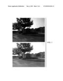
[0006]However, this method works poorly in back-lit scene, where the background of the scene is lit by some strong light source. FIG. 1 is an embodiment of two scenes with different back light. The top one is captured using basic auto exposure method and the bottom one is captured using proposed auto exposure method. A desirable auto exposure method for digital cameras should be universal, since digital cameras will be used to capture different kinds of images. It also should have low computation complexity and low memory, due to the cost and shot-to-shot constraints of digital cameras.
[0007]Currently, many auto exposure methods are proposed for digital cameras. Some of them do not consider backlit scenes. Others detect backlit scenes by histogram analysis and fuzzy logic resulting in high computational complexity and high memory requirement. Therefore, there is a need for a method and/or apparatus for improving back light detection.
SUMMARY
[0008]Embodiments of the current invention generally relate to a method and apparatus for determining the type of back light of an image. The method includes computing an average luminance of the center region of at least a portion of the image, computing the average luminance of the image, wherein the average luminance is aveImage, computing the ratio of the average image luminance to the average center luminance, wherein the ratio=aveImage/aveCenter, determining that the scene related to the image is a backlit scene if the ratio is greater than a predetermined value and performing exposure compensation for the backlit scene and determining that the scene related to the image is a normal scene if the ratio is less than a predetermined value and computing the new exposure value for normal scene by utilizing the equation Exp2=Exp1 * lum_ref/aveImage.
BRIEF DESCRIPTION OF THE DRAWINGS
[0009]So that the manner in which the above recited features of the present invention can be understood in detail, a more particular description of the invention, briefly summarized above, may be had by reference to embodiments, some of which are illustrated in the appended drawings. It is to be noted, however, that the appended drawings illustrate only typical embodiments of this invention and are therefore not to be considered limiting of its scope, for the invention may admit to other equally effective embodiments.
[0010]FIG. 1 is an embodiment of two (2) scenes with different back light;
[0011]FIG. 2 is an embodiment depicting various regions of an image;
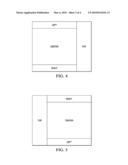
[0012]FIG. 3 is an embodiment depicting two (2) images with different orientation;
[0013]FIG. 4 is another embodiment depicting various regions of an image;
[0014]FIG. 5 is yet another embodiment depicting various regions of an image; and
[0015]FIG. 6 is a flow diagram depicting an embodiment of a method determining the type of back light of an image.
DETAILED DESCRIPTION
[0016]An image is captured with a default or previous exposure value, which is denoted by exp1. The mean luminance of the captured image is computed and is denoted by lum_ave. A right exposure value is set and denoted by exp2. The right exposure may be set based on a reference luminance value, lum_ref. Thus,
Exp2=Exp1*lum_ref/lum_ave.
[0017]The backlit scene is detected first and then exposure compensation for backlit scene is performed. One observation is that the luminance of the top of a backlit scene may be larger than the average luminance of the image. In such an embodiment, local luminance mean may be used to detect backlit scene.
[0018]In such an embodiment, the top of the image is assumed to be the top of the scene. This assumption may not true if the camera is rotated while capturing the image. There are three different orientations: specifically, rotation by 90, 180, and 270 degrees. We do not consider rotation by 180 degree, which rarely happens for cameras.
[0019]In FIG. 3, the left image is rotated by 90 degree, and the right image is rotated by 270 degree. A scene orientation detection method may be used to detect correct scene orientation. Once the orientation is known, the image orientation may be easily corrected. However, orientation correction is not required in the proposed auto exposure method.
[0020]When the image has been rotated by 90 degree, the average luminance of the center region (denoted by aveCenter) is computed, as shown in FIG. 4. The height of the region may be 90% of the image height and the width may be equal to 75% of the image width. Step 2-5 listed above are followed to compute exposure control. When the image has been rotated by 270 degree, the average luminance of the center region is computed, as shown in FIG. 5.
[0021]When a scene orientation detection method is unavailable or impractical, the three average luminance values of the center regions specified in FIG. 2, FIG. 4, and FIG. 5 are computed. The minimal aveCenter in Step 2-5 above is used.
[0022]FIG. 6 is a flow diagram depicting an embodiment of a method 600 for determining the type of back light of an image. FIG. 6 starts at step 602 and proceeds to step 604. At step 604, the method 600 computes the average luminance of the center region, which is herein denoted by the average luminance by aveCenter, as shown in FIG. 4. The height of the region may be 75% of the image height and the width may be equal to 90% of the image width. At step 606, the method 600 computes the average luminance of the entire image, denoted by aveImage. At step 608, the method 600 computes the ratio of the average image luminance to the average center luminance: ratio=aveImage/aveCenter.
[0023]At step 610, the method 600 decides If ratio>t1, backlit scene and, Otherwise, determines the scene to be a normal scene. At step 612, the method 600 computes the new exposure value for normal scene by: Exp2=Exp1 * lum_ref/aveImage. At step 614, the method 600 performs exposure compensation for backlit scene by: Exp2=Exp1 * lum_ref/(t2*aveImage+(1-t2)*aveCenter). In this embodiment, t1 and t2 are two parameters, which may be set to 1.3, and 0.5, respectively. The method 600 ends at step 616.
[0024]Hence, in one embodiment, this method and/or apparatus uses luminance average and is simpler than the current solutions. Moreover, one embodiment, this method and/or apparatus considers different image orientation, while others do not.
[0025]The main advantages of our approach are this approach a) works well for different image orientation, b) has very low computation complexity, c) has very low memory requirement, d) can be easily implemented on existing hardware image processors.
[0026]While the foregoing is directed to embodiments of the present invention, other and further embodiments of the invention may be devised without departing from the basic scope thereof, and the scope thereof is determined by the claims that follow.
Claims:
1. A method of a digital signal processor for determining the type of back
light of an image, the method comprising:computing an average luminance
of the center region of at least a portion of the image, wherein the
average luminance is aveCenter;computing the average luminance of the
image, wherein the average luminance is aveImage;computing the ratio of
the average image luminance to the average center luminance, wherein the
ratio=aveImage/aveCenter;determining that the scene related to the image
is a backlit scene if the ratio is greater than a predetermined value and
performing exposure compensation for the backlit scene by utilizing the
equationExp2=Exp1* lum_ref/(t2*aveImage+(1-t2)*aveCenter); anddetermining
that the scene related to the image is a normal scene if the ratio is
less than a predetermined value and computing the new exposure value for
normal scene by utilizing the equationExp2=Exp1* lum_ref/aveImage.
1. An apparatus for determining the type of back light of an image, comprising:means for computing an average luminance of the center region of at least a portion of the image, wherein the average luminance is aveCenter;means for computing the average luminance of the image, wherein the average luminance is aveImage;means for computing the ratio of the average image luminance to the average center luminance, wherein the ratio=aveImage/aveCenter;means for determining that the scene related to the image is a backlit scene if the ratio is greater than a predetermined value and performing exposure compensation for the backlit scene by utilizing the equationExp2=Exp1* lum_ref/(t2*aveImage+(1-t2)*aveCenter); andmeans for determining that the scene related to the image is a normal scene if the ratio is less than a predetermined value and computing the new exposure value for normal scene by utilizing the equationExp2=Exp1* lum_ref/aveImage.
3. A computer readable medium comprising computer instructions, when executed perform a method, the method of a digital signal processor for determining the type of back light of an image, the method comprising:computing an average luminance of the center region of at least a portion of the image, wherein the average luminance is aveCenter;computing the average luminance of the image, wherein the average luminance is aveImage;computing the ratio of the average image luminance to the average center luminance, wherein the ratio=aveImage/aveCenter;determining that the scene related to the image is a backlit scene if the ratio is greater than a predetermined value and performing exposure compensation for the backlit scene by utilizing the equationExp2=Exp1* lum_ref/(t2*aveImage+(1-t2)*aveCenter); anddetermining that the scene related to the image is a normal scene if the ratio is less than a predetermined value and computing the new exposure value for normal scene by utilizing the equationExp2=Exp1* lum_ref/aveImage.
Description:
CROSS-REFERENCE TO RELATED APPLICATIONS
[0001]This application claims benefit of U.S. provisional patent application Ser. No. 61/111,081, filed Nov. 4, 2008, which is herein incorporated by reference.
BACKGROUND OF THE INVENTION
[0002]1. Field of the Invention
[0003]Embodiments of the present invention generally relate to a method and apparatus for auto-exposure of an image.
[0004]2. Description of the Related Art
[0005]Digital cameras are widely used in many applications, such as digital still cameras, camera phones, camcorders, and video surveillance equipment. A typical camera has an auto-exposure module to control exposure under different lighting conditions. A basic auto exposure method matches the average luminance of an image to a predefined reference value by adjusting exposure values.
[0006]However, this method works poorly in back-lit scene, where the background of the scene is lit by some strong light source. FIG. 1 is an embodiment of two scenes with different back light. The top one is captured using basic auto exposure method and the bottom one is captured using proposed auto exposure method. A desirable auto exposure method for digital cameras should be universal, since digital cameras will be used to capture different kinds of images. It also should have low computation complexity and low memory, due to the cost and shot-to-shot constraints of digital cameras.
[0007]Currently, many auto exposure methods are proposed for digital cameras. Some of them do not consider backlit scenes. Others detect backlit scenes by histogram analysis and fuzzy logic resulting in high computational complexity and high memory requirement. Therefore, there is a need for a method and/or apparatus for improving back light detection.
SUMMARY
[0008]Embodiments of the current invention generally relate to a method and apparatus for determining the type of back light of an image. The method includes computing an average luminance of the center region of at least a portion of the image, computing the average luminance of the image, wherein the average luminance is aveImage, computing the ratio of the average image luminance to the average center luminance, wherein the ratio=aveImage/aveCenter, determining that the scene related to the image is a backlit scene if the ratio is greater than a predetermined value and performing exposure compensation for the backlit scene and determining that the scene related to the image is a normal scene if the ratio is less than a predetermined value and computing the new exposure value for normal scene by utilizing the equation Exp2=Exp1 * lum_ref/aveImage.
BRIEF DESCRIPTION OF THE DRAWINGS
[0009]So that the manner in which the above recited features of the present invention can be understood in detail, a more particular description of the invention, briefly summarized above, may be had by reference to embodiments, some of which are illustrated in the appended drawings. It is to be noted, however, that the appended drawings illustrate only typical embodiments of this invention and are therefore not to be considered limiting of its scope, for the invention may admit to other equally effective embodiments.
[0010]FIG. 1 is an embodiment of two (2) scenes with different back light;
[0011]FIG. 2 is an embodiment depicting various regions of an image;
[0012]FIG. 3 is an embodiment depicting two (2) images with different orientation;
[0013]FIG. 4 is another embodiment depicting various regions of an image;
[0014]FIG. 5 is yet another embodiment depicting various regions of an image; and
[0015]FIG. 6 is a flow diagram depicting an embodiment of a method determining the type of back light of an image.
DETAILED DESCRIPTION
[0016]An image is captured with a default or previous exposure value, which is denoted by exp1. The mean luminance of the captured image is computed and is denoted by lum_ave. A right exposure value is set and denoted by exp2. The right exposure may be set based on a reference luminance value, lum_ref. Thus,
Exp2=Exp1*lum_ref/lum_ave.
[0017]The backlit scene is detected first and then exposure compensation for backlit scene is performed. One observation is that the luminance of the top of a backlit scene may be larger than the average luminance of the image. In such an embodiment, local luminance mean may be used to detect backlit scene.
[0018]In such an embodiment, the top of the image is assumed to be the top of the scene. This assumption may not true if the camera is rotated while capturing the image. There are three different orientations: specifically, rotation by 90, 180, and 270 degrees. We do not consider rotation by 180 degree, which rarely happens for cameras.
[0019]In FIG. 3, the left image is rotated by 90 degree, and the right image is rotated by 270 degree. A scene orientation detection method may be used to detect correct scene orientation. Once the orientation is known, the image orientation may be easily corrected. However, orientation correction is not required in the proposed auto exposure method.
[0020]When the image has been rotated by 90 degree, the average luminance of the center region (denoted by aveCenter) is computed, as shown in FIG. 4. The height of the region may be 90% of the image height and the width may be equal to 75% of the image width. Step 2-5 listed above are followed to compute exposure control. When the image has been rotated by 270 degree, the average luminance of the center region is computed, as shown in FIG. 5.
[0021]When a scene orientation detection method is unavailable or impractical, the three average luminance values of the center regions specified in FIG. 2, FIG. 4, and FIG. 5 are computed. The minimal aveCenter in Step 2-5 above is used.
[0022]FIG. 6 is a flow diagram depicting an embodiment of a method 600 for determining the type of back light of an image. FIG. 6 starts at step 602 and proceeds to step 604. At step 604, the method 600 computes the average luminance of the center region, which is herein denoted by the average luminance by aveCenter, as shown in FIG. 4. The height of the region may be 75% of the image height and the width may be equal to 90% of the image width. At step 606, the method 600 computes the average luminance of the entire image, denoted by aveImage. At step 608, the method 600 computes the ratio of the average image luminance to the average center luminance: ratio=aveImage/aveCenter.
[0023]At step 610, the method 600 decides If ratio>t1, backlit scene and, Otherwise, determines the scene to be a normal scene. At step 612, the method 600 computes the new exposure value for normal scene by: Exp2=Exp1 * lum_ref/aveImage. At step 614, the method 600 performs exposure compensation for backlit scene by: Exp2=Exp1 * lum_ref/(t2*aveImage+(1-t2)*aveCenter). In this embodiment, t1 and t2 are two parameters, which may be set to 1.3, and 0.5, respectively. The method 600 ends at step 616.
[0024]Hence, in one embodiment, this method and/or apparatus uses luminance average and is simpler than the current solutions. Moreover, one embodiment, this method and/or apparatus considers different image orientation, while others do not.
[0025]The main advantages of our approach are this approach a) works well for different image orientation, b) has very low computation complexity, c) has very low memory requirement, d) can be easily implemented on existing hardware image processors.
[0026]While the foregoing is directed to embodiments of the present invention, other and further embodiments of the invention may be devised without departing from the basic scope thereof, and the scope thereof is determined by the claims that follow.
User Contributions:
Comment about this patent or add new information about this topic:
Images included with this patent application:
 |  |
 |  |
| Similar patent applications: | |
| Date | Title |
|---|---|
| 2011-03-10 | Apparatus and method for compensating for back light of image |
| 2008-12-04 | System and method for increasing the brightness of an image |
| 2011-02-24 | Detection of defective pixels in an image sensor |
| 2010-06-17 | System and method for the detection of de-interlacing of scaled video |
| 2010-09-30 | Method of removing an artefact from an image |
| New patent applications in this class: | |
| Date | Title |
|---|---|
| 2017-08-17 | Conversion method and conversion apparatus |
| 2016-07-07 | Systems and methods for photmetric normalization in array cameras |
| 2016-06-23 | Method and system for configuring an imaging device for the reception of digital pulse recognition information |
| 2016-06-23 | Imaging device and imaging method |
| 2016-06-16 | Image pickup device, image pickup method, and program |
| New patent applications from these inventors: | |
| Date | Title |
|---|---|
| 2020-09-17 | Switchover control techniques for dual-sensor camera system |
| 2016-11-17 | Video image stabilization |
| 2016-01-07 | Low light video image stabilization strength modulation |
| 2015-12-03 | Video rolling shutter correction for lens movement in optical image stabilization cameras |
| 2015-12-03 | Video image stabilization |
| Top Inventors for class "Television" | |
| Rank | Inventor's name |
|---|---|
| 1 | Canon Kabushiki Kaisha |
| 2 | Kia Silverbrook |
| 3 | Peter Corcoran |
| 4 | Petronel Bigioi |
| 5 | Eran Steinberg |