Patent application title: RAILING
Inventors:
Chong-Yi Lo (Sherman Oaks, CA, US)
IPC8 Class: AE04H1714FI
USPC Class:
256 6512
Class name: Rail to post rail extended through post or post extended through rail including distinct locking means
Publication date: 2010-03-18
Patent application number: 20100065802
nd rails intersected with each other and fixed
stably together by connecting plates hidden inside the rails. The
connecting plate has a wing formed at a preset position between every two
posts. The wing has a hole at its center. Each of the rails has a long
space defined by three walls of its inverted U-shape, a rectangular
opening bored in its top side for being correspondingly inserted by the
post, and a female-threaded tube extended downward from an upper inner
wall for corresponding to a hole of a wing of the connecting plate so
that a screw can be inserted from under the hole to threadably engage
with the female-threaded tube to keep the rails fixed with the connecting
plates. The railing is thus assembled stably by means of the connecting
plates and the screws that are hidden inside the rails, obtaining an
aesthetic appearance.Claims:
1. A railing, comprising:plural pickets and rails that are fixedly
intersected with each other by means of plural connecting plates,wherein
said connecting plates correspond in number to said rails and are
respectively and transversely fixed at one side of said pickets by means
of plural screws to keep said pickets connected to stand side by side, a
horizontal wing formed to protrude sidewise from an intermediate portion
of each of said connecting plates between every two said pickets and
bored with a hole at its center; andeach of said rails provided with a
long space defined by three walls in an inverted U-shape, an opening
bored in a top side of said rail for corresponding to each said picket
passing through said rail, said connecting plates hidden inside said
rails, a female-threaded tube extended downward from an inner wall of a
top side of said rails for corresponding to said hole of said wing of a
respective one of said connecting plates so that a screw can be inserted
from under said hole of said wing to threadably engage with said
female-threaded tube of said rail to keep said rail fixed with said
connecting plate,wherein each of said connecting plates is provided with
a horizontal contact short wall formed at its top to contact with an
inner wall of a top side of said rail.
2. (canceled)
3. The railing as claimed in claim 1, wherein said opening of said rails is formed rectangular, and said pickets are formed square and able to pass through said opening of said rails.Description:
BACKGROUND OF THE INVENTION
[0001]1. Field of the Invention
[0002]This invention relates to a railing, particularly to one having connecting plates and screws used to fix the posts with the rails invisibly hidden inside the rails.
[0003]2. Description of the Prior Art
[0004]Commonly, a conventional fence made of metal is formed by intersection of plural posts and rails. Each intersection of the rails and the posts is fastened by a screw. However, the head of the screw is always exposed out of the rails, making the fence look ugly.
SUMMARY OF THE INVENTION
[0005]The objective of this invention is to offer a railing formed by intersection of plural posts and rails stably fixed by connecting plates and screws that are invisibly hidden inside the rails, so as to enable the railing to maintain an esthetic appearance.
[0006]The connecting plates are transversely fixed with the posts at the intersections of the posts and the rails, respectively provided with a wing to protrude sidewise between every two posts. The wing is bored with a hole at its center. Each of the rails is provided with a long space defined by three walls of its inverted U-shape, and a rectangular opening bored in its top side for being correspondingly inserted by the post. The rails are to be laid on a top of the connecting plates, also respectively provided with a female-threaded tube extended downward from an inner wall of its top side for corresponding to a hole of a wing of the connecting plate so that a screw can be inserted from the bottom of the hole to threadably engage with the female-threaded tube to keep the rails fixed with the connecting plates. With the connecting plates and the screws hidden inside the rails to keep the posts and the rails stably fixed, an esthetic appearance of the railing can be obtained.
BRIEF DESCRIPTION OF DRAWINGS
[0007]This invention is better understood by referring to the accompanying drawings, wherein:
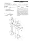
[0008]FIG. 1 is a perspective view of a preferred embodiment of a railing in the present invention;
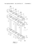
[0009]FIG. 2 is a partial exploded perspective view of the preferred embodiment of a railing in the present invention;
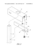
[0010]FIG. 3 is another perspective view of the preferred embodiment of a railing in the present invention;
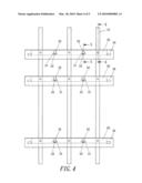
[0011]FIG. 4 is a front view of the preferred embodiment of a railing in the present invention;
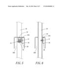
[0012]FIG. 5 is a cross-sectional view of the line of "5-5" in FIG. 4; and
[0013]FIG. 6 is a cross-sectional view of the line of "6-6" in FIG. 4.
DETAILED DESCRIPTION OF THE PREFERRED EMBODIMENT
[0014]As shown in FIGS. 1˜3, a preferred embodiment of a railing 1 in the present invention is provided with plural posts 10 and plural rails 30, which are intersected with each other, and plural connecting plates 20.
[0015]The posts 10 are formed square, respectively provided with plural threaded holes 11 bored properly spaced apart in their outer wall to be jointed with the rails 30.
[0016]The connecting plates 20 are needed as many as the rails 30, respectively and transversely fixed at one side of the posts 10 by means of screws 12 screwed in the threaded holes 11 of the posts 10, so that the posts 10 are connected to stand side by side. Each of the connecting plates 20 is provided with a horizontal low contact wall 201 formed by having its top portion vertically bent, and a horizontal wing 21 formed to protrude sidewise between every two posts 10. The wing 21 is bored with a hole 22 at its center.
[0017]Each of the rails 30 is shaped as an inverted U, forming a long space 300 among its three walls, having a rectangular opening 31 bored in its top side for being correspondingly inserted by the post 10 entering from the space 300. When the rail 30 is laid down on the connecting plates 20, the inner wall of its top side is to automatically contact with the contact wall 201 of the connecting plate 20, with the connecting plate 20 hidden inside the rail 30. In addition, the rail 30 is also provided with a female-threaded short tube 32 extended downward from the inner wall of its top side in corresponding to the hole 22 of the wing 21 of the connecting plate 20, so that a screw 23 can be inserted from under the hole 22 of the wing 21 to threadably engage with the female-threaded tube 32 of the rail 30 to keep the rail 30 fixed stably with the connecting plate 20.
[0018]In assembling the railing 1, as shown in FIGS. 4˜6, the connecting plate 20 is first fixed with posts 10 at the lowest fixing position. Next, the rail 30 is inserted from the top of the posts 10 through the openings 31 to rest on the contact wall 201 of the connecting plate 20, and each of the female-threaded tubes 32 of the rail 30 is threadably engaged with the screw 23 inserted from under the hole 22 of the wing 21 so as to keep the rail 30 fixed with the connecting plate 20. According to the process described above, all the posts 10 can be fixed with all rails 30 orderly leveled up, thus finishing assembly of the railing 1. With the rails 30 fixed with the connecting plates 20 by means of the screws 23 threadably engaged with the threaded holes 32 as mentioned previously, the rails 30 can be firmly fixed with the posts 10 without moving upward. Moreover, the connecting plates 20, including the wings 21 and the screws 12 and 23, are all hidden inside the rails 30 so that the railing 1 can completely maintain an esthetic appearance.
[0019]As the openings 31 of the rails 30 are formed rectangular as shown in FIG. 2, they can be vertically passed by the posts 10 even if the rails 30 are inclined owing to an inclined ground. So, the railing 1 can be installed on an inclined ground as well.
[0020]While the preferred embodiment of the invention has been described above, it will be recognized and understood that various modifications may be made therein and the appended claims are intended to cover all such modifications that may fall within the spirit and scope of the invention.
Claims:
1. A railing, comprising:plural pickets and rails that are fixedly
intersected with each other by means of plural connecting plates,wherein
said connecting plates correspond in number to said rails and are
respectively and transversely fixed at one side of said pickets by means
of plural screws to keep said pickets connected to stand side by side, a
horizontal wing formed to protrude sidewise from an intermediate portion
of each of said connecting plates between every two said pickets and
bored with a hole at its center; andeach of said rails provided with a
long space defined by three walls in an inverted U-shape, an opening
bored in a top side of said rail for corresponding to each said picket
passing through said rail, said connecting plates hidden inside said
rails, a female-threaded tube extended downward from an inner wall of a
top side of said rails for corresponding to said hole of said wing of a
respective one of said connecting plates so that a screw can be inserted
from under said hole of said wing to threadably engage with said
female-threaded tube of said rail to keep said rail fixed with said
connecting plate,wherein each of said connecting plates is provided with
a horizontal contact short wall formed at its top to contact with an
inner wall of a top side of said rail.
2. (canceled)
3. The railing as claimed in claim 1, wherein said opening of said rails is formed rectangular, and said pickets are formed square and able to pass through said opening of said rails.
Description:
BACKGROUND OF THE INVENTION
[0001]1. Field of the Invention
[0002]This invention relates to a railing, particularly to one having connecting plates and screws used to fix the posts with the rails invisibly hidden inside the rails.
[0003]2. Description of the Prior Art
[0004]Commonly, a conventional fence made of metal is formed by intersection of plural posts and rails. Each intersection of the rails and the posts is fastened by a screw. However, the head of the screw is always exposed out of the rails, making the fence look ugly.
SUMMARY OF THE INVENTION
[0005]The objective of this invention is to offer a railing formed by intersection of plural posts and rails stably fixed by connecting plates and screws that are invisibly hidden inside the rails, so as to enable the railing to maintain an esthetic appearance.
[0006]The connecting plates are transversely fixed with the posts at the intersections of the posts and the rails, respectively provided with a wing to protrude sidewise between every two posts. The wing is bored with a hole at its center. Each of the rails is provided with a long space defined by three walls of its inverted U-shape, and a rectangular opening bored in its top side for being correspondingly inserted by the post. The rails are to be laid on a top of the connecting plates, also respectively provided with a female-threaded tube extended downward from an inner wall of its top side for corresponding to a hole of a wing of the connecting plate so that a screw can be inserted from the bottom of the hole to threadably engage with the female-threaded tube to keep the rails fixed with the connecting plates. With the connecting plates and the screws hidden inside the rails to keep the posts and the rails stably fixed, an esthetic appearance of the railing can be obtained.
BRIEF DESCRIPTION OF DRAWINGS
[0007]This invention is better understood by referring to the accompanying drawings, wherein:
[0008]FIG. 1 is a perspective view of a preferred embodiment of a railing in the present invention;
[0009]FIG. 2 is a partial exploded perspective view of the preferred embodiment of a railing in the present invention;
[0010]FIG. 3 is another perspective view of the preferred embodiment of a railing in the present invention;
[0011]FIG. 4 is a front view of the preferred embodiment of a railing in the present invention;
[0012]FIG. 5 is a cross-sectional view of the line of "5-5" in FIG. 4; and
[0013]FIG. 6 is a cross-sectional view of the line of "6-6" in FIG. 4.
DETAILED DESCRIPTION OF THE PREFERRED EMBODIMENT
[0014]As shown in FIGS. 1˜3, a preferred embodiment of a railing 1 in the present invention is provided with plural posts 10 and plural rails 30, which are intersected with each other, and plural connecting plates 20.
[0015]The posts 10 are formed square, respectively provided with plural threaded holes 11 bored properly spaced apart in their outer wall to be jointed with the rails 30.
[0016]The connecting plates 20 are needed as many as the rails 30, respectively and transversely fixed at one side of the posts 10 by means of screws 12 screwed in the threaded holes 11 of the posts 10, so that the posts 10 are connected to stand side by side. Each of the connecting plates 20 is provided with a horizontal low contact wall 201 formed by having its top portion vertically bent, and a horizontal wing 21 formed to protrude sidewise between every two posts 10. The wing 21 is bored with a hole 22 at its center.
[0017]Each of the rails 30 is shaped as an inverted U, forming a long space 300 among its three walls, having a rectangular opening 31 bored in its top side for being correspondingly inserted by the post 10 entering from the space 300. When the rail 30 is laid down on the connecting plates 20, the inner wall of its top side is to automatically contact with the contact wall 201 of the connecting plate 20, with the connecting plate 20 hidden inside the rail 30. In addition, the rail 30 is also provided with a female-threaded short tube 32 extended downward from the inner wall of its top side in corresponding to the hole 22 of the wing 21 of the connecting plate 20, so that a screw 23 can be inserted from under the hole 22 of the wing 21 to threadably engage with the female-threaded tube 32 of the rail 30 to keep the rail 30 fixed stably with the connecting plate 20.
[0018]In assembling the railing 1, as shown in FIGS. 4˜6, the connecting plate 20 is first fixed with posts 10 at the lowest fixing position. Next, the rail 30 is inserted from the top of the posts 10 through the openings 31 to rest on the contact wall 201 of the connecting plate 20, and each of the female-threaded tubes 32 of the rail 30 is threadably engaged with the screw 23 inserted from under the hole 22 of the wing 21 so as to keep the rail 30 fixed with the connecting plate 20. According to the process described above, all the posts 10 can be fixed with all rails 30 orderly leveled up, thus finishing assembly of the railing 1. With the rails 30 fixed with the connecting plates 20 by means of the screws 23 threadably engaged with the threaded holes 32 as mentioned previously, the rails 30 can be firmly fixed with the posts 10 without moving upward. Moreover, the connecting plates 20, including the wings 21 and the screws 12 and 23, are all hidden inside the rails 30 so that the railing 1 can completely maintain an esthetic appearance.
[0019]As the openings 31 of the rails 30 are formed rectangular as shown in FIG. 2, they can be vertically passed by the posts 10 even if the rails 30 are inclined owing to an inclined ground. So, the railing 1 can be installed on an inclined ground as well.
[0020]While the preferred embodiment of the invention has been described above, it will be recognized and understood that various modifications may be made therein and the appended claims are intended to cover all such modifications that may fall within the spirit and scope of the invention.
User Contributions:
Comment about this patent or add new information about this topic:
Images included with this patent application:
 |  |
 |  |
 |  |
| New patent applications in this class: | |
| Date | Title |
|---|---|
| 2016-06-09 | Baluster connector |
| 2016-04-07 | Method and apparatus for constructing and repairing fence or railings |
| 2016-04-07 | Method and apparatus for construction when vertical and horizontal members are used |
| 2015-10-22 | Railing assembly with interference fit-based coupling |
| 2015-01-22 | Method and apparatus for construction when vertical and horizontal members are used |
| New patent applications from these inventors: | |
| Date | Title |
|---|---|
| 2011-06-02 | Combined structure of fence posts and rails |
| 2011-01-06 | Hidden-fastener fence |
| 2010-09-23 | Fence |
| 2009-07-02 | Fence |
| Top Inventors for class "Fences" | |
| Rank | Inventor's name |
|---|---|
| 1 | Dallas James |
| 2 | Robert E. Platt |
| 3 | Gordon Duffy |
| 4 | Jason Duffy |
| 5 | Matthew Carlyle Sherstad |