Patent application title: Inductor for Inductor Hardening of Metal, Rod-Shaped Toothed Racks
Inventors:
Leif Markegaard (Skien, NO)
Assignees:
EFD INDUCTION GMBH
IPC8 Class: AH05B602FI
USPC Class:
219637
Class name: Inductive heating specific heating application rod
Publication date: 2010-03-11
Patent application number: 20100059506
hardening of a metallic rod-shaped toothed rack,
wherein a first outer surface of the toothed rack provided with the teeth
is substantially planar and a remaining second outer surface of the
toothed rack in cross-section is profiled, wherein the inductor has a
substantially rod-shaped first inductor element that extends parallel to
a longitudinal axis of the toothed rack. The first inductor element
extends across an entire length of the toothed rack to be hardened along
the first outer surface provided with the teeth and hardens the first
outer surface of the toothed rack. The the toothed rack and the inductor
during the hardening process are arranged stationarily.Claims:
1.-7. (canceled)
8. An inductor for induction hardening of a metallic rod-shaped toothed rack, wherein a first outer surface of the toothed rack provided with the teeth is substantially planar and a remaining second outer surface of the toothed rack in cross-section is profiled, wherein the inductor comprises a substantially rod-shaped first inductor element that extends parallel to a longitudinal axis of the toothed rack, which first inductor element extends across an entire length of the toothed rack to be hardened along the first outer surface provided with the teeth and hardens the first outer surface of the toothed rack, and wherein the toothed rack and the inductor during the hardening process are arranged stationarily.
9. The Inductor according to claim 8, comprising two or more of said first inductor element arranged parallel to one another at the first outer surface of the toothed rack provided with the teeth.
10. The inductor according to claim 8, comprising a substantially rod-shaped second inductor element that extends parallel to the longitudinal axis of the toothed rack, which second inductor element extends along the remaining second outer surface of the toothed rack and hardens the remaining second outer surface area of the toothed rack
11. The inductor according to claim 10, comprising two or more of said second inductor element arranged parallel to one another at the remaining second outer surface of the toothed rack.
12. The inductor according to claim 10, wherein the first and second inductor elements are connected to one another by connecting elements and form a mechanically rigid assembly.
13. The inductor according to claim 12, wherein the first and second inductor elements are substantially of same length and the first and second inductor elements that are directly neighboring one another are connected to one another at ends thereof by the connecting elements that extend transversely to the first and second inductor elements.
14. The inductor according to claim 10, wherein the first and second inductor elements are connected electrically in series or electrically in parallel.
15. The inductor according to claim 9, wherein the first and second inductor elements are connected electrically in series or electrically in parallel.Description:
[0001]The invention concerns an inductor for induction hardening of
metallic, rod-shaped toothed racks according to the preamble of claim 1.
[0002]The inductor according to the invention is designed for toothed racks that have a non-round cross-section. Such toothed racks are substantially planar in the area of the teeth that are sequentially arranged behind one another while the remaining cross-sectional contour is profiled, for example, round or substantially oval or rectangular or trapezoidal.
[0003]When toothed racks are induction-hardened it is known to arrange the toothed rack stationarily and to move an inductor of a stirrup shape during induction hardening across the length of the toothed rack. This, as a whole, is technically complex and primarily also relatively time-consuming with regard to the processing duration.
[0004]Based on this, it is an object of the invention to provide an improved inductor for induction hardening of metallic rod-shaped toothed racks with which the induction process can be performed in a simpler and faster way.
[0005]The technical solution is characterized by the features of the characterizing portion of claim 1.
[0006]The basic idea of the inductor according to the invention for induction hardening of metallic elongate toothed racks that have a certain cross-sectional profile resides in that the inductor is to be formed in accordance with the given contour of the toothed rack to be hardened of at least one inductor element, preferably of several individual inductor elements. This is to be understood such that the tooth side of the toothed rack to be hardened has correlated therewith an inductor element. Inasmuch as this inductor element is comprised of several individual inductor elements, the sum thereof defines the inductor as a whole. In that the inductor elements are arranged and aligned in the longitudinal direction of the toothed racks, the inductor can be designed such that it extends across the entire length of the elongate toothed rack to be hardened. In this way, it is possible to harden the toothed rack, despite a complex shape, in a targeted way in a single working step. In particular, by means of the configuration of the inductor according to the invention it is possible to arrange in accordance with the present invention the inductor as well as the toothed rack stationarily so that with a single electrical power supply either only the tooth side of the toothed racks or the entire toothed rack (i.e., inclusive of the back) can be hardened without a relative movement between the toothed rack and the inductor being required. With respect to the procedure, known technologies can be employed. For example, the known conventional method steps can be performed, for example, pre-hardening and subsequently the actual hardening step. For example, it is also possible to operate the inductor with one or several frequencies. As a whole, with the inductor according to the invention, on the one hand, the quality of the induction-hardened toothed rack is improved and, on the other hand, the processing duration can be shortened.
[0007]According to the embodiment of claim 2, the tooth side of the toothed rack, for example, can have correlated therewith a pair of rod-shaped inductor elements. By means of an appropriate geometric configuration and arrangement of the rod-shaped inductor elements, it is thus possible to obtain an optimal hardening of the tooth side of the toothed rack.
[0008]The embodiment according to claim 3 proposes to not only inductively harden the tooth side of the toothed rack in the afore described manner but also the back of the toothed rack. This is to be understood such that in the area of the back of the toothed rack corresponding rod-shaped inductor elements are provided that extend parallel to the longitudinal axis of the toothed rack and that harden the back of the toothed rack. In this arrangement, also with a single electric power supply the back, and thus the complete toothed rack, is hardened, i.e., the tooth side as well as the back of the toothed rack. The electrical power supply to the inductor elements is realized preferably simultaneously.
[0009]The embodiment according to claim 4 proposes in this connection also that inductor element pairs are provided for hardening the back, for example, when the back of the toothed rack in cross-sectional profile is round or oval. Depending on the cross-sectional contour, even more inductors can be provided wherein each contour section has its own rod-shaped inductor element assigned to it. By means of this corresponding geometric configuration and arrangement of rod-shaped inductor elements, an optimal hardening of the entire toothed rack can be obtained.
[0010]The embodiment according to claim 5 proposes that the inductor as a whole forms a mechanically rigid assembly. This means that the inductor with its inductor elements in this constructive assembly must first be positioned relative to the toothed rack to be hardened in order to subsequently perform the hardening process with appropriate electrical power supply of the inductor. The connecting elements between the individual inductor elements not only have the task to provide a mechanical connection but also preferably these connecting elements form the electrical connection between the inductor elements, be it in serial connection or in parallel connection.
[0011]In accordance with the embodiment of claim 6 the connecting elements are arranged between inductor elements that neighbor one another. This means that the inductor as a whole is very compact and, in particular, in case of the elongate tooth rack is moreover of a slim configuration and that primarily no unnecessary conducting paths must be bridged. By means of the transversely extending connecting elements the current flows in accordance with the inductor elements, viewed in longitudinal direction of the toothed rack, back and forth within the inductor, i.e., forward and back and again forward etc.
[0012]A further embodiment proposes according to claim 7 that the inductor elements are connected by corresponding connecting elements electrically in serial connection. According to the course and arrangement of the inductor elements and the connecting elements, in this way an inductor results that is convoluted within itself and is matched to the contour of the toothed rack to be hardened. Alternatively, it is also possible to connect the inductor elements electrically in parallel. On the one hand, it is conceivable in this connection that the inductor elements are all connected to the same voltage source. On the other hand, it is also conceivable that the inductor elements are differently energized.
[0013]One embodiment of an inductor according to the invention for induction hardening of metallic toothed racks will be disclosed in the following with the aid of the drawing. It is shown in:
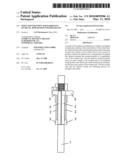
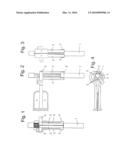
[0014]FIG. 1 a view of the inductor for hardening toothed racks;
[0015]FIG. 2 a side view of the inductor in FIG. 1;
[0016]FIG. 3 a rear view of the inductor in FIG. 1;
[0017]FIG. 4 a view in longitudinal direction of the toothed rack.
[0018]The embodiment in FIGS. 1 to 4 shows an inductor for hardening a toothed rack 1. The inductor is comprised of a total of four elongate inductor elements 2 that extend parallel to the toothed rack 1. In this connection, two inductor elements 2 are positioned opposite one another relative to the tooth profile of the toothed rack 1 while two inductor elements 2 extend in the area of the back of the toothed rack 1.
[0019]Ends of the inductor elements 2 that neighbor one another are connected by connecting elements 3 mechanically as well as electrically. This means that the inductor elements 2 together with their connecting elements 3 are connected electrically in series wherein the current along the inductor elements 2, after passing through the respective connecting element 3, flows back and forth in longitudinal direction of the toothed rack 1.
LIST OF REFERENCE CHARACTERS
[0020]1 toothed rack
[0021]2 inductor element
[0022]3 connecting element
Claims:
1.-7. (canceled)
8. An inductor for induction hardening of a metallic rod-shaped toothed rack, wherein a first outer surface of the toothed rack provided with the teeth is substantially planar and a remaining second outer surface of the toothed rack in cross-section is profiled, wherein the inductor comprises a substantially rod-shaped first inductor element that extends parallel to a longitudinal axis of the toothed rack, which first inductor element extends across an entire length of the toothed rack to be hardened along the first outer surface provided with the teeth and hardens the first outer surface of the toothed rack, and wherein the toothed rack and the inductor during the hardening process are arranged stationarily.
9. The Inductor according to claim 8, comprising two or more of said first inductor element arranged parallel to one another at the first outer surface of the toothed rack provided with the teeth.
10. The inductor according to claim 8, comprising a substantially rod-shaped second inductor element that extends parallel to the longitudinal axis of the toothed rack, which second inductor element extends along the remaining second outer surface of the toothed rack and hardens the remaining second outer surface area of the toothed rack
11. The inductor according to claim 10, comprising two or more of said second inductor element arranged parallel to one another at the remaining second outer surface of the toothed rack.
12. The inductor according to claim 10, wherein the first and second inductor elements are connected to one another by connecting elements and form a mechanically rigid assembly.
13. The inductor according to claim 12, wherein the first and second inductor elements are substantially of same length and the first and second inductor elements that are directly neighboring one another are connected to one another at ends thereof by the connecting elements that extend transversely to the first and second inductor elements.
14. The inductor according to claim 10, wherein the first and second inductor elements are connected electrically in series or electrically in parallel.
15. The inductor according to claim 9, wherein the first and second inductor elements are connected electrically in series or electrically in parallel.
Description:
[0001]The invention concerns an inductor for induction hardening of
metallic, rod-shaped toothed racks according to the preamble of claim 1.
[0002]The inductor according to the invention is designed for toothed racks that have a non-round cross-section. Such toothed racks are substantially planar in the area of the teeth that are sequentially arranged behind one another while the remaining cross-sectional contour is profiled, for example, round or substantially oval or rectangular or trapezoidal.
[0003]When toothed racks are induction-hardened it is known to arrange the toothed rack stationarily and to move an inductor of a stirrup shape during induction hardening across the length of the toothed rack. This, as a whole, is technically complex and primarily also relatively time-consuming with regard to the processing duration.
[0004]Based on this, it is an object of the invention to provide an improved inductor for induction hardening of metallic rod-shaped toothed racks with which the induction process can be performed in a simpler and faster way.
[0005]The technical solution is characterized by the features of the characterizing portion of claim 1.
[0006]The basic idea of the inductor according to the invention for induction hardening of metallic elongate toothed racks that have a certain cross-sectional profile resides in that the inductor is to be formed in accordance with the given contour of the toothed rack to be hardened of at least one inductor element, preferably of several individual inductor elements. This is to be understood such that the tooth side of the toothed rack to be hardened has correlated therewith an inductor element. Inasmuch as this inductor element is comprised of several individual inductor elements, the sum thereof defines the inductor as a whole. In that the inductor elements are arranged and aligned in the longitudinal direction of the toothed racks, the inductor can be designed such that it extends across the entire length of the elongate toothed rack to be hardened. In this way, it is possible to harden the toothed rack, despite a complex shape, in a targeted way in a single working step. In particular, by means of the configuration of the inductor according to the invention it is possible to arrange in accordance with the present invention the inductor as well as the toothed rack stationarily so that with a single electrical power supply either only the tooth side of the toothed racks or the entire toothed rack (i.e., inclusive of the back) can be hardened without a relative movement between the toothed rack and the inductor being required. With respect to the procedure, known technologies can be employed. For example, the known conventional method steps can be performed, for example, pre-hardening and subsequently the actual hardening step. For example, it is also possible to operate the inductor with one or several frequencies. As a whole, with the inductor according to the invention, on the one hand, the quality of the induction-hardened toothed rack is improved and, on the other hand, the processing duration can be shortened.
[0007]According to the embodiment of claim 2, the tooth side of the toothed rack, for example, can have correlated therewith a pair of rod-shaped inductor elements. By means of an appropriate geometric configuration and arrangement of the rod-shaped inductor elements, it is thus possible to obtain an optimal hardening of the tooth side of the toothed rack.
[0008]The embodiment according to claim 3 proposes to not only inductively harden the tooth side of the toothed rack in the afore described manner but also the back of the toothed rack. This is to be understood such that in the area of the back of the toothed rack corresponding rod-shaped inductor elements are provided that extend parallel to the longitudinal axis of the toothed rack and that harden the back of the toothed rack. In this arrangement, also with a single electric power supply the back, and thus the complete toothed rack, is hardened, i.e., the tooth side as well as the back of the toothed rack. The electrical power supply to the inductor elements is realized preferably simultaneously.
[0009]The embodiment according to claim 4 proposes in this connection also that inductor element pairs are provided for hardening the back, for example, when the back of the toothed rack in cross-sectional profile is round or oval. Depending on the cross-sectional contour, even more inductors can be provided wherein each contour section has its own rod-shaped inductor element assigned to it. By means of this corresponding geometric configuration and arrangement of rod-shaped inductor elements, an optimal hardening of the entire toothed rack can be obtained.
[0010]The embodiment according to claim 5 proposes that the inductor as a whole forms a mechanically rigid assembly. This means that the inductor with its inductor elements in this constructive assembly must first be positioned relative to the toothed rack to be hardened in order to subsequently perform the hardening process with appropriate electrical power supply of the inductor. The connecting elements between the individual inductor elements not only have the task to provide a mechanical connection but also preferably these connecting elements form the electrical connection between the inductor elements, be it in serial connection or in parallel connection.
[0011]In accordance with the embodiment of claim 6 the connecting elements are arranged between inductor elements that neighbor one another. This means that the inductor as a whole is very compact and, in particular, in case of the elongate tooth rack is moreover of a slim configuration and that primarily no unnecessary conducting paths must be bridged. By means of the transversely extending connecting elements the current flows in accordance with the inductor elements, viewed in longitudinal direction of the toothed rack, back and forth within the inductor, i.e., forward and back and again forward etc.
[0012]A further embodiment proposes according to claim 7 that the inductor elements are connected by corresponding connecting elements electrically in serial connection. According to the course and arrangement of the inductor elements and the connecting elements, in this way an inductor results that is convoluted within itself and is matched to the contour of the toothed rack to be hardened. Alternatively, it is also possible to connect the inductor elements electrically in parallel. On the one hand, it is conceivable in this connection that the inductor elements are all connected to the same voltage source. On the other hand, it is also conceivable that the inductor elements are differently energized.
[0013]One embodiment of an inductor according to the invention for induction hardening of metallic toothed racks will be disclosed in the following with the aid of the drawing. It is shown in:
[0014]FIG. 1 a view of the inductor for hardening toothed racks;
[0015]FIG. 2 a side view of the inductor in FIG. 1;
[0016]FIG. 3 a rear view of the inductor in FIG. 1;
[0017]FIG. 4 a view in longitudinal direction of the toothed rack.
[0018]The embodiment in FIGS. 1 to 4 shows an inductor for hardening a toothed rack 1. The inductor is comprised of a total of four elongate inductor elements 2 that extend parallel to the toothed rack 1. In this connection, two inductor elements 2 are positioned opposite one another relative to the tooth profile of the toothed rack 1 while two inductor elements 2 extend in the area of the back of the toothed rack 1.
[0019]Ends of the inductor elements 2 that neighbor one another are connected by connecting elements 3 mechanically as well as electrically. This means that the inductor elements 2 together with their connecting elements 3 are connected electrically in series wherein the current along the inductor elements 2, after passing through the respective connecting element 3, flows back and forth in longitudinal direction of the toothed rack 1.
LIST OF REFERENCE CHARACTERS
[0020]1 toothed rack
[0021]2 inductor element
[0022]3 connecting element
User Contributions:
Comment about this patent or add new information about this topic:
Images included with this patent application:
 |  |
| New patent applications in this class: | |
| Date | Title |
|---|---|
| 2011-01-06 | Application of electric induction energy for manufacture of irregularly shaped shafts with cylindrical components including non-unitarily forged crankshafts and camshafts |
| 2009-11-05 | Induction heater |
| Top Inventors for class "Electric heating" | |
| Rank | Inventor's name |
|---|---|
| 1 | Steven R. Peters |
| 2 | Shou-Shan Fan |
| 3 | Chen Feng |
| 4 | Kai-Li Jiang |
| 5 | Chang-Hong Liu |