Patent application title: MOUNTING MECHANISM FOR DATA STORAGE DEVICE
Inventors:
Chin-Wen Yeh (Tu-Cheng, TW)
Zhi-Jian Peng (Shenzhen City, CN)
Assignees:
HONG FU JIN PRECISION INDUSTRY (ShenZhen) CO., LTD.
HON HAI PRECISION INDUSTRY CO., LTD.
IPC8 Class: AA47B8100FI
USPC Class:
3122232
Class name: Supports: cabinet structure for particular electrical device or component housing for computer or computer related equipment
Publication date: 2009-12-24
Patent application number: 20090315435
mounting a data storage device includes a drive
bracket. The drive bracket includes two parallel side panels, each of
which forms a pillar extending inwards toward each other. The data
storage device includes two side walls capable of being received between
two side panels of the drive bracket. Each of the side walls defines a
groove therein. A surface of the corresponding groove is configured to
match with the outer surface of the corresponding pillar so that the
groove is capable of engaging with the pillar.Claims:
1. A mounting mechanism comprising: a drive bracket comprising two
parallel side panels, the two parallel side panels each forming a pillar
extending inwards toward each other; anda data storage device comprising
two side walls capable of being received between the two parallel side
panels of the drive bracket, each of the side walls defining a groove
therein, a surface of the corresponding groove being configured to match
with an outer surface of the corresponding pillar so that the groove is
capable of engaging with the pillar;wherein one of the side walls of the
data storage device defines a plurality of screw holes, and the
corresponding side panel of the drive bracket defines as plurality of
holes in alignment with the screw holes of the data storage device, and a
plurality of screws are located in the corresponding holes and screw
holes.
2. The mounting mechanism of claim 1, wherein each of the side panels of the drive bracket forms at least one support piece on which the data storage device is supported.
3. The mounting mechanism of claim 2, wherein the at least one support piece is below the corresponding pillar.
4. (canceled)
5. The mounting mechanism of claim 1, wherein the outer surface of each pillar is arcuate, and a bottom surface of corresponding groove is arcuate to smoothly contact with the outer surface of the corresponding pillar.
6. A mounting mechanism comprising:a data storage device comprising at least one side wall, the at least one side wall defining a groove therein;a drive bracket comprising two side panels configured to sandwich the data storage device therebetween, at least one of the two side panels forming a pillar thereon configured to engage with the groove;wherein an outer surface of the pillar is configured to match with the groove, the outer surface of the pillar is arcuate, and a bottom surface of the groove corresponds to the outer surface of the pillar; the outer surface of the pillar and the bottom surface of the groove are in contact.
7-8. (canceled)
9. The mounting mechanism of claim 6, wherein each of the two side panels forms at least one support piece by which the data storage device is supported.
10. The mounting mechanism of claim 9, wherein the at least one support piece of each of the two side panels is below the pillar.
11. The mounting mechanism of claim 6, wherein the at least one side wall of the data storage device defines a plurality of screw holes, and the corresponding side panel of the drive bracket defines a plurality of screw holes in alignment with the screw holes of the data storage device for screws screwing into.
12-15. (canceled)Description:
BACKGROUND
[0001]1. Technical Field
[0002]The present invention relates to mounting mechanisms for mounting data storage devices in a computer enclosure.
[0003]2. Description of Related Art
[0004]A means is disclosed in U.S. Pat. No. 7,408,771 for mounting a data storage device, which includes a drive bracket and a rotating member. The data storage device has sliding members at opposite sides thereof. The drive bracket includes a pair of guiding slots for receiving the sliding members. A clip extends from the drive bracket. The rotating member is pivotably mounted on the first side panel. The sliding members of the data storage device slide into the guiding slots. The rotating member is rotated to engage with the latching tab and secure at least one of the sliding members in the guiding slot. However, the mounting assembly is complicated, and additional components, such as the rotating member, are needed.
[0005]Therefore, a mounting mechanism for data storage device is desired to overcome the above-described deficiency.
BRIEF DESCRIPTION OF THE DRAWINGS
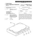
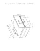
[0006]FIG. 1 is an exploded, isometric view of an embodiment of a mounting mechanism and a data storage device;
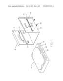
[0007]FIG. 2 is an assembled, isometric view of the mounting mechanism and the data storage device of FIG. 1.
DETAILED DESCRIPTION OF THE EMBODIMENTS
[0008]Referring to FIG. 1, an exemplary embodiment of a mounting mechanism for mounting a data storage device 30 of an electronic device includes a drive bracket 10. The drive bracket 10 includes two parallel side panels 11 and 13. Each of the side panels 11 and 13 forms an elongate pillar 19. The two pillars 19 extend inwards and toward each other. An outer surface of each pillar 19 is arcuate and smooth. Each of the side panels 11 and 13 also forms two horizontal support pieces 14 extending towards the other side panel and below the pillar 19. The side panel 13 defines a plurality of screw holes 17 beside the pillar 19 of the side panel 13.
[0009]The data storage device 30 includes a pair of sidewalls 31 and a bottom wall 34. Each of the sidewalls 31 defines a groove 39 corresponding to each of the pillars 19 of the drive bracket 10. A bottom surface of the groove 39 is shaped arcuate to match the outer surface of each of the pillars 19. A plurality of screw holes 37 is defined in a sidewall 31 corresponding to the plurality of screw holes 17 of the side panel 13.
[0010]Referring to FIGS. 1 and 2, in assembly of the data storage device 30 on the drive bracket 10, the data storage device 30 is moved into the drive bracket 10 with the bottom wall 34 supported by the support pieces 14 of the drive bracket 10. The data storage device 30 slides on the support pieces 14. The pillars 19 of the drive bracket 10 engage the grooves 39 of the drive bracket 10., and the outer surfaces of the pillars 19 slide smoothly along the bottom surfaces of the grooves 39. Because the outer surfaces of the pillars 19 and the bottom surfaces of the grooves 39 are arcuate, the data storage device 30 slides into the drive bracket 10 smoothly. The data storage device 30 slides until the screw holes 37 of the data storage device 30 are in alignment with the screw holes 17 of the drive bracket 10. A plurality of screws 50 are screwed into the screw holes 17 and 37 to fix the data storage device 30 into the drive bracket 10.
[0011]In disassembly of the data storage device 30 from the drive bracket 10, the screws 50 are first unscrewed from the screw holes 17 and 37. Then, the data storage device 30 is slid out of the drive bracket 10 until the pillars 19 are no longer in contact with the grooves 39 of the data storage device 30. Therefore, the data storage device 30 is detached from the drive bracket 10.
[0012]It is to be understood, however, that even though numerous characteristics and advantages of the embodiments have been set forth in the foregoing description, together with details of the structure and function of the embodiments, the disclosure is illustrative only, and changes may be made in details, especially in matters of shape, size, and arrangement of parts within the principles of the invention to the full extent indicated by the broad general meaning of the terms in which the appended claims are expressed.
Claims:
1. A mounting mechanism comprising: a drive bracket comprising two
parallel side panels, the two parallel side panels each forming a pillar
extending inwards toward each other; anda data storage device comprising
two side walls capable of being received between the two parallel side
panels of the drive bracket, each of the side walls defining a groove
therein, a surface of the corresponding groove being configured to match
with an outer surface of the corresponding pillar so that the groove is
capable of engaging with the pillar;wherein one of the side walls of the
data storage device defines a plurality of screw holes, and the
corresponding side panel of the drive bracket defines as plurality of
holes in alignment with the screw holes of the data storage device, and a
plurality of screws are located in the corresponding holes and screw
holes.
2. The mounting mechanism of claim 1, wherein each of the side panels of the drive bracket forms at least one support piece on which the data storage device is supported.
3. The mounting mechanism of claim 2, wherein the at least one support piece is below the corresponding pillar.
4. (canceled)
5. The mounting mechanism of claim 1, wherein the outer surface of each pillar is arcuate, and a bottom surface of corresponding groove is arcuate to smoothly contact with the outer surface of the corresponding pillar.
6. A mounting mechanism comprising:a data storage device comprising at least one side wall, the at least one side wall defining a groove therein;a drive bracket comprising two side panels configured to sandwich the data storage device therebetween, at least one of the two side panels forming a pillar thereon configured to engage with the groove;wherein an outer surface of the pillar is configured to match with the groove, the outer surface of the pillar is arcuate, and a bottom surface of the groove corresponds to the outer surface of the pillar; the outer surface of the pillar and the bottom surface of the groove are in contact.
7-8. (canceled)
9. The mounting mechanism of claim 6, wherein each of the two side panels forms at least one support piece by which the data storage device is supported.
10. The mounting mechanism of claim 9, wherein the at least one support piece of each of the two side panels is below the pillar.
11. The mounting mechanism of claim 6, wherein the at least one side wall of the data storage device defines a plurality of screw holes, and the corresponding side panel of the drive bracket defines a plurality of screw holes in alignment with the screw holes of the data storage device for screws screwing into.
12-15. (canceled)
Description:
BACKGROUND
[0001]1. Technical Field
[0002]The present invention relates to mounting mechanisms for mounting data storage devices in a computer enclosure.
[0003]2. Description of Related Art
[0004]A means is disclosed in U.S. Pat. No. 7,408,771 for mounting a data storage device, which includes a drive bracket and a rotating member. The data storage device has sliding members at opposite sides thereof. The drive bracket includes a pair of guiding slots for receiving the sliding members. A clip extends from the drive bracket. The rotating member is pivotably mounted on the first side panel. The sliding members of the data storage device slide into the guiding slots. The rotating member is rotated to engage with the latching tab and secure at least one of the sliding members in the guiding slot. However, the mounting assembly is complicated, and additional components, such as the rotating member, are needed.
[0005]Therefore, a mounting mechanism for data storage device is desired to overcome the above-described deficiency.
BRIEF DESCRIPTION OF THE DRAWINGS
[0006]FIG. 1 is an exploded, isometric view of an embodiment of a mounting mechanism and a data storage device;
[0007]FIG. 2 is an assembled, isometric view of the mounting mechanism and the data storage device of FIG. 1.
DETAILED DESCRIPTION OF THE EMBODIMENTS
[0008]Referring to FIG. 1, an exemplary embodiment of a mounting mechanism for mounting a data storage device 30 of an electronic device includes a drive bracket 10. The drive bracket 10 includes two parallel side panels 11 and 13. Each of the side panels 11 and 13 forms an elongate pillar 19. The two pillars 19 extend inwards and toward each other. An outer surface of each pillar 19 is arcuate and smooth. Each of the side panels 11 and 13 also forms two horizontal support pieces 14 extending towards the other side panel and below the pillar 19. The side panel 13 defines a plurality of screw holes 17 beside the pillar 19 of the side panel 13.
[0009]The data storage device 30 includes a pair of sidewalls 31 and a bottom wall 34. Each of the sidewalls 31 defines a groove 39 corresponding to each of the pillars 19 of the drive bracket 10. A bottom surface of the groove 39 is shaped arcuate to match the outer surface of each of the pillars 19. A plurality of screw holes 37 is defined in a sidewall 31 corresponding to the plurality of screw holes 17 of the side panel 13.
[0010]Referring to FIGS. 1 and 2, in assembly of the data storage device 30 on the drive bracket 10, the data storage device 30 is moved into the drive bracket 10 with the bottom wall 34 supported by the support pieces 14 of the drive bracket 10. The data storage device 30 slides on the support pieces 14. The pillars 19 of the drive bracket 10 engage the grooves 39 of the drive bracket 10., and the outer surfaces of the pillars 19 slide smoothly along the bottom surfaces of the grooves 39. Because the outer surfaces of the pillars 19 and the bottom surfaces of the grooves 39 are arcuate, the data storage device 30 slides into the drive bracket 10 smoothly. The data storage device 30 slides until the screw holes 37 of the data storage device 30 are in alignment with the screw holes 17 of the drive bracket 10. A plurality of screws 50 are screwed into the screw holes 17 and 37 to fix the data storage device 30 into the drive bracket 10.
[0011]In disassembly of the data storage device 30 from the drive bracket 10, the screws 50 are first unscrewed from the screw holes 17 and 37. Then, the data storage device 30 is slid out of the drive bracket 10 until the pillars 19 are no longer in contact with the grooves 39 of the data storage device 30. Therefore, the data storage device 30 is detached from the drive bracket 10.
[0012]It is to be understood, however, that even though numerous characteristics and advantages of the embodiments have been set forth in the foregoing description, together with details of the structure and function of the embodiments, the disclosure is illustrative only, and changes may be made in details, especially in matters of shape, size, and arrangement of parts within the principles of the invention to the full extent indicated by the broad general meaning of the terms in which the appended claims are expressed.
User Contributions:
Comment about this patent or add new information about this topic:
| People who visited this patent also read: | |
| Patent application number | Title |
|---|---|
| 20140127810 | NUCLEIC ACID SILENCING SEQUENCES |
| 20140127809 | Perfusion Device and Method |
| 20140127808 | POROUS CELL SCAFFOLD AND PRODUCTION METHOD THEREOF |
| 20140127807 | Method for Promoting Differentiation of Pluripotent Stem Cells into Cardiac Muscle Cells |
| 20140127806 | MODIFIED LAMININ AND USE THEREOF |
Images included with this patent application:
 |  |
 |
| Similar patent applications: | |
| Date | Title |
|---|---|
| 2011-09-29 | Fixing mechanism for storage device |
| 2011-06-30 | Tilt mechanism for electronic device |
| 2009-11-12 | Retraction mechanism for a drawer |
| 2010-02-04 | Pull-out mechanism for a drawer |
| 2010-12-02 | Shockproof assembly for flat storage device |
| New patent applications in this class: | |
| Date | Title |
|---|---|
| 2022-05-05 | Portable information device and double-sided adhesive tape |
| 2019-05-16 | Disk drive cover with spring force compression feature |
| 2017-08-17 | Assembly for a computer system and cable covering unit for an assembly |
| 2016-06-02 | Touchpad supporting device |
| 2016-05-26 | Handle structure and server using the same |
| New patent applications from these inventors: | |
| Date | Title |
|---|---|
| 2014-02-20 | Goods delivery switch |
| 2014-02-20 | Supporting apparatus for vending machine |
| 2014-02-13 | Vending machine with merchandise buffering device |
| 2014-01-16 | Vending machine and method of outputting merchandises of vending machine |
| 2013-05-16 | Fixture for installing hard disk |
| Top Inventors for class "Supports: cabinet structure" | |
| Rank | Inventor's name |
|---|---|
| 1 | Yun-Lung Chen |
| 2 | Karl-Friedrich Laible |
| 3 | Jae Hoon Lim |
| 4 | Chen-Lu Fan |
| 5 | Wen-Tang Peng |