Patent application title: Quick Switching Mechanism for Side Discharge Unit and Grass Chopper Unit of a Lawn Mower
Inventors:
Ting Wang (Danyang, CN)
Chaojie Zhang (Danyang, CN)
Shengli Wang (Danyang, CN)
Wenchen Song (Danyang, CN)
Assignees:
Jiangsu World Plant-Protecting Machinery Co., Ltd.
IPC8 Class: AA01D4300FI
USPC Class:
56200
Class name: Rotating cutting reel catchers discharging
Publication date: 2009-12-17
Patent application number: 20090308043
ention relates to a quick switching mechanism for
the side discharge unit and the chopper unit of a lawn mower: a side
discharge unit and a chopper unit are mounted at the grass outlet on a
cutting platform; wherein, the side discharge unit comprises a grass
discharging gear shaft, a grass discharging hood mounted on the grass
discharging gear shaft; the grass chopper unit comprises a grass chopping
gear shaft, a grass chopping closing plate mounted on the grass chopping
gear shaft; the small gear on the grass discharging gear shaft is engaged
to the big gear on the grass chopping gear shaft; a guy wire is mounted
on the cutting platform, and is connected to a rotary arm mounted on one
end of the grass chopping gear shaft. In the invention, the current grass
discharging hood is kept, and therefore the safety of grass discharging
is not compromised; during the mowing process, when the mower runs into a
place (e.g., a kerb, shrub, etc.) where the grass discharging process is
difficult, the mower can be switched from grass discharging mode to grass
chopping mode immediately; after the mower passes the place, it can be
switched back to grass discharging mode quickly; if the mower runs into a
narrow place (e.g., the space between two trees), the mower can be
switching from wide discharging mode to narrow discharging mode
immediately; the mower can be switched back quickly after it passes
through the place.Claims:
1. A quick switching mechanism for the side discharge unit and grass
chopper unit of a lawn mower, comprising: a side discharge unit and a
grass chopper unit are mounted at the grass outlet of a cutting platform,
wherein, the side discharge unit comprises a grass discharging gear shaft
and a grass discharging hood mounted on the grass discharging gear shaft;
the grass chopper unit comprises a grass chopping gear shaft and a grass
chopping closing plate mounted on the grass chopping gear shaft; a small
gear on the grass discharging gear shaft is engaged with a big gear on
the grass chopping gear shaft, a guy wire is mounted on the cutting
platform, and is connected to a rotary arm on one end of the grass
chopping gear shaft.
2. The quick switching mechanism for the side discharge unit and the grass chopper unit of a lawn mower according to claim 1, wherein, a torsion spring is mounted on the grass discharging gear shaft, and the rotary arm fixed to the grass chopping gear shaft is connected with the guy wire.Description:
FIELD OF THE INVENTION
[0001]The present invention relates to a lawn mower, particularly to a side discharge unit and grass chopper unit of a lawn mower.
BACKGROUND OF THE INVENTION
[0002]Single-blade and multi-blade lawn mowers are available in the current market, and these lawn mowers usually have side discharging and grass chopping functions. During the side grass discharging process, a discharging hood is mounted on the grass outlet to control the flow direction of the grass scraps and provide safety protection; during the grass chopping process, a closing plate is mounted on the grass outlet, to prevent the grass scraps from discharging out. However, such a structure has the following drawbacks: 1. Since the grass discharging hood and the grass chopping closing plate have to be mounted separately, appropriate tools (e.g., a wrench) are required when switching between the grass discharging and the grass chopping happens, and the switching operation is inconvenient. 2. After the grass discharging hood is mounted, the width of the entire lawn mower is increased, and therefore it is adverse for the mower to move through narrow places.
[0003]At present, a method for solving the above technical problems is: a rotary grass chopping closing plate can be mounted on the current lawn mower, so that the quick switching between the side grass discharging and the grass chopping can be achieved by rotating the grass chopping closing plate. However, such structure can't provide grass discharging hood, thus there is no safety protection in the grass discharging direction during side grass discharging process.
SUMMARY OF THE INVENTION
[0004]The object of the present invention is to overcome the drawbacks in the prior art and provide a quick switching mechanism for switching between the side discharge unit and the chopper unit of a lawn mower, which can achieve quick switching between the side grass discharging function and the grass chopping function, without compromising the performance and safety of the lawn mower.
[0005]The technical scheme employed in the invention is: a side discharge unit and a chopper unit are mounted at the grass outlet on a cutting platform; wherein, the side discharge unit comprises a grass discharging gear shaft, a grass discharging hood mounted on the grass discharging gear shaft; the grass chopper unit comprises a grass chopping gear shaft, a grass chopping closing plate mounted on the grass chopping gear shaft; the small gear on the grass discharging gear shaft is engaged to the big gear on the grass chopping gear shaft; a guy wire is mounted on the cutting platform, and is connected to a rotary arm mounted on one end of the grass chopping gear shaft.
[0006]In the invention, the current grass discharging hood is reserved, and therefore the safety of grass discharging is not compromised; during the mowing process, when the mower runs into a place (e.g., a kerb, shrub, etc.) where the grass discharging process is difficult to perform, the mower can be switched from the grass discharging mode to the grass chopping mode immediately; after the mower passes the place, it can be switched back to the grass discharging mode immediately; if the mower runs into a narrow place (e.g., the space between two trees), the mower can be switching from wide discharging mode to narrow discharging mode immediately; the mower can be switched back immediately after it passes through the place.
BRIEF DESCRIPTION OF THE DRAWINGS
[0007]Hereafter the invention will be further detailed descripted in the embodiments, with reference to the accompany drawings.
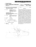
[0008]FIG. 1 is a structural diagram of the invention in side discharging state;
[0009]FIG. 2 is a structural diagram of the invention in grass chopping state;
[0010]Wherein, in the drawings: 1. cutting platform; 2. guy wire; 3. grass discharging gear shaft; 4. grass discharging hood; 5. grass chopping gear shaft; 6. grass chopping closing plate; 7. rotary arm; 8. small gear; 9. big gear; 10. torsion spring.
DETAILED DESCRIPTION OF THE EMBODIMENTS
[0011]As shown in FIG. 1 and FIG. 2, in this invention, the interaction between a grass discharging hood 4 and a grass chopping closing plate 6 is achieved with a pair of gear shafts (grass discharging gear shaft 3 and grass chopping gear shaft 5), by means of the engagement between the small gear 8 on the grass discharging gear shaft 3 and the big gear 9 on the grass chopping gear shaft 5. The control mechanism of the mower has two positions, which match the side discharging state shown in FIG. 1 and the grass chopping state shown in FIG. 2. In addition, the control mechanism can be positively stopped in the grass chopping position. A side discharge unit and a chopper unit are mounted at the grass outlet on a cutting platform 1; wherein, the side discharge unit comprises a grass discharging gear shaft 3, a grass discharging hood 4 mounted on the grass discharging gear shaft 3; the grass chopper unit comprises a grass chopping gear shaft 5, a grass chopping closing plate 6 mounted on the grass chopping gear shaft 5; the small gear 8 on the grass discharging gear shaft 3 is engaged to the big gear 9 on the grass chopping gear shaft 5; a guy wire 2 is mounted on the cutting platform 1, and is connected to a rotary arm 7 mounted on one end of the grass chopping gear shaft 5, and the other end of the guy wire 2 is connected to the control mechanism of the mower. A torsion spring 10 is mounted on the grass discharging gear shaft 3; under the force of the torsion spring 10, the grass discharging gear shaft 3 always afford a torque in clockwise direction.
[0012]When this invention is performed, the control mechanism of the mower in the invention is switched to from the grass discharging position to the grass chopping position, the control mechanism pulls the rotary arm 7 on the grass chopping gear shaft 5 in the help of the guy wire 2, so that the grass chopping gear shaft 5 rotates in clockwise direction, and drives the grass chopping closing plate 6 to rotate downwards to the grass chopping state. Meanwhile, by means of the engagement between the small gear 8 and the big gear 9, the grass chopping gear shaft 3 is driven to overcome the spring torque to rotate in counter clockwise direction, and the grass discharging gear shaft 3 drives the grass discharging hood 4 to rotate to the grass chopping position (as shown in FIG. 2), so as to achieve grass chopping function.
[0013]When the control mechanism departs from the positive stop mechanism in the grass chopping position, the grass discharging gear shaft 3 rotates in clockwise direction under the spring torque, and drives the grass discharging hood 4 to rotate downwards to the grass discharging position, and, by means of the engagement between the small gear 8 and the big gear 9, drives the grass chopping gear shaft 5 to rotate in counter clockwise direction, so that the grass chopping gear shaft 5 drives the grass chopping closing plate 6 to rotate upwards to the grass discharging state. At the same time, the rotary arm 7 on the grass chopping gear shaft 5 pulls the guy wire 2, and to return the control mechanism to grass discharging position in the help of the guy wire 2 (as shown in FIG. 1), so as to achieve the side grass discharging function.
Claims:
1. A quick switching mechanism for the side discharge unit and grass
chopper unit of a lawn mower, comprising: a side discharge unit and a
grass chopper unit are mounted at the grass outlet of a cutting platform,
wherein, the side discharge unit comprises a grass discharging gear shaft
and a grass discharging hood mounted on the grass discharging gear shaft;
the grass chopper unit comprises a grass chopping gear shaft and a grass
chopping closing plate mounted on the grass chopping gear shaft; a small
gear on the grass discharging gear shaft is engaged with a big gear on
the grass chopping gear shaft, a guy wire is mounted on the cutting
platform, and is connected to a rotary arm on one end of the grass
chopping gear shaft.
2. The quick switching mechanism for the side discharge unit and the grass chopper unit of a lawn mower according to claim 1, wherein, a torsion spring is mounted on the grass discharging gear shaft, and the rotary arm fixed to the grass chopping gear shaft is connected with the guy wire.
Description:
FIELD OF THE INVENTION
[0001]The present invention relates to a lawn mower, particularly to a side discharge unit and grass chopper unit of a lawn mower.
BACKGROUND OF THE INVENTION
[0002]Single-blade and multi-blade lawn mowers are available in the current market, and these lawn mowers usually have side discharging and grass chopping functions. During the side grass discharging process, a discharging hood is mounted on the grass outlet to control the flow direction of the grass scraps and provide safety protection; during the grass chopping process, a closing plate is mounted on the grass outlet, to prevent the grass scraps from discharging out. However, such a structure has the following drawbacks: 1. Since the grass discharging hood and the grass chopping closing plate have to be mounted separately, appropriate tools (e.g., a wrench) are required when switching between the grass discharging and the grass chopping happens, and the switching operation is inconvenient. 2. After the grass discharging hood is mounted, the width of the entire lawn mower is increased, and therefore it is adverse for the mower to move through narrow places.
[0003]At present, a method for solving the above technical problems is: a rotary grass chopping closing plate can be mounted on the current lawn mower, so that the quick switching between the side grass discharging and the grass chopping can be achieved by rotating the grass chopping closing plate. However, such structure can't provide grass discharging hood, thus there is no safety protection in the grass discharging direction during side grass discharging process.
SUMMARY OF THE INVENTION
[0004]The object of the present invention is to overcome the drawbacks in the prior art and provide a quick switching mechanism for switching between the side discharge unit and the chopper unit of a lawn mower, which can achieve quick switching between the side grass discharging function and the grass chopping function, without compromising the performance and safety of the lawn mower.
[0005]The technical scheme employed in the invention is: a side discharge unit and a chopper unit are mounted at the grass outlet on a cutting platform; wherein, the side discharge unit comprises a grass discharging gear shaft, a grass discharging hood mounted on the grass discharging gear shaft; the grass chopper unit comprises a grass chopping gear shaft, a grass chopping closing plate mounted on the grass chopping gear shaft; the small gear on the grass discharging gear shaft is engaged to the big gear on the grass chopping gear shaft; a guy wire is mounted on the cutting platform, and is connected to a rotary arm mounted on one end of the grass chopping gear shaft.
[0006]In the invention, the current grass discharging hood is reserved, and therefore the safety of grass discharging is not compromised; during the mowing process, when the mower runs into a place (e.g., a kerb, shrub, etc.) where the grass discharging process is difficult to perform, the mower can be switched from the grass discharging mode to the grass chopping mode immediately; after the mower passes the place, it can be switched back to the grass discharging mode immediately; if the mower runs into a narrow place (e.g., the space between two trees), the mower can be switching from wide discharging mode to narrow discharging mode immediately; the mower can be switched back immediately after it passes through the place.
BRIEF DESCRIPTION OF THE DRAWINGS
[0007]Hereafter the invention will be further detailed descripted in the embodiments, with reference to the accompany drawings.
[0008]FIG. 1 is a structural diagram of the invention in side discharging state;
[0009]FIG. 2 is a structural diagram of the invention in grass chopping state;
[0010]Wherein, in the drawings: 1. cutting platform; 2. guy wire; 3. grass discharging gear shaft; 4. grass discharging hood; 5. grass chopping gear shaft; 6. grass chopping closing plate; 7. rotary arm; 8. small gear; 9. big gear; 10. torsion spring.
DETAILED DESCRIPTION OF THE EMBODIMENTS
[0011]As shown in FIG. 1 and FIG. 2, in this invention, the interaction between a grass discharging hood 4 and a grass chopping closing plate 6 is achieved with a pair of gear shafts (grass discharging gear shaft 3 and grass chopping gear shaft 5), by means of the engagement between the small gear 8 on the grass discharging gear shaft 3 and the big gear 9 on the grass chopping gear shaft 5. The control mechanism of the mower has two positions, which match the side discharging state shown in FIG. 1 and the grass chopping state shown in FIG. 2. In addition, the control mechanism can be positively stopped in the grass chopping position. A side discharge unit and a chopper unit are mounted at the grass outlet on a cutting platform 1; wherein, the side discharge unit comprises a grass discharging gear shaft 3, a grass discharging hood 4 mounted on the grass discharging gear shaft 3; the grass chopper unit comprises a grass chopping gear shaft 5, a grass chopping closing plate 6 mounted on the grass chopping gear shaft 5; the small gear 8 on the grass discharging gear shaft 3 is engaged to the big gear 9 on the grass chopping gear shaft 5; a guy wire 2 is mounted on the cutting platform 1, and is connected to a rotary arm 7 mounted on one end of the grass chopping gear shaft 5, and the other end of the guy wire 2 is connected to the control mechanism of the mower. A torsion spring 10 is mounted on the grass discharging gear shaft 3; under the force of the torsion spring 10, the grass discharging gear shaft 3 always afford a torque in clockwise direction.
[0012]When this invention is performed, the control mechanism of the mower in the invention is switched to from the grass discharging position to the grass chopping position, the control mechanism pulls the rotary arm 7 on the grass chopping gear shaft 5 in the help of the guy wire 2, so that the grass chopping gear shaft 5 rotates in clockwise direction, and drives the grass chopping closing plate 6 to rotate downwards to the grass chopping state. Meanwhile, by means of the engagement between the small gear 8 and the big gear 9, the grass chopping gear shaft 3 is driven to overcome the spring torque to rotate in counter clockwise direction, and the grass discharging gear shaft 3 drives the grass discharging hood 4 to rotate to the grass chopping position (as shown in FIG. 2), so as to achieve grass chopping function.
[0013]When the control mechanism departs from the positive stop mechanism in the grass chopping position, the grass discharging gear shaft 3 rotates in clockwise direction under the spring torque, and drives the grass discharging hood 4 to rotate downwards to the grass discharging position, and, by means of the engagement between the small gear 8 and the big gear 9, drives the grass chopping gear shaft 5 to rotate in counter clockwise direction, so that the grass chopping gear shaft 5 drives the grass chopping closing plate 6 to rotate upwards to the grass discharging state. At the same time, the rotary arm 7 on the grass chopping gear shaft 5 pulls the guy wire 2, and to return the control mechanism to grass discharging position in the help of the guy wire 2 (as shown in FIG. 1), so as to achieve the side grass discharging function.
User Contributions:
Comment about this patent or add new information about this topic:
| People who visited this patent also read: | |
| Patent application number | Title |
|---|---|
| 20120181647 | MICROMECHANICAL TUNABLE FABRY-PEROT INTERFEROMETER AND A METHOD FOR PRODUCING THE SAME |
| 20120181646 | CAMERA MODULE AND METHOD OF MANUFACTURING THE SAME |
| 20120181645 | PHOTODETECTOR OPTIMIZED BY METAL TEXTURING PROVIDED ON THE REAR SURFACE |
| 20120181644 | LOW POWER MAGNETIC RANDOM ACCESS MEMORY CELL |
| 20120181643 | SPIN TRANSPORT DEVICE |
Images included with this patent application:
 |  |
| Similar patent applications: | |
| Date | Title |
|---|---|
| 2012-12-27 | Mulching lawn mower rear discharge pathway and shield |
| 2012-10-18 | Charging station for battery-powered lawn mower |
| 2010-09-09 | Method for eliminating leaf stalks a harvested crop flow |
| 2012-12-13 | Decoring mechanism with mechanized harvester |
| 2009-06-25 | Machine for the harvest of stalk-like plants |
| New patent applications in this class: | |
| Date | Title |
|---|---|
| 2010-08-19 | Lawnmower assembly |
| New patent applications from these inventors: | |
| Date | Title |
|---|---|
| 2009-12-17 | Sliding pulley drive mechanism in cutting platform of lawn mower |
| Top Inventors for class "Harvesters" | |
| Rank | Inventor's name |
|---|---|
| 1 | Randy Lohrentz |
| 2 | Christopher T. Sauerwein |
| 3 | Benjamin M. Lovett |
| 4 | Neil Gordon Barnett |
| 5 | Martin E. Pruitt |