Patent application title: Method for predicting the power capacity of electrical energy stores
Inventors:
Eberhard Schoch (Stuttgart-Feuerbach, DE)
IPC8 Class: AG01R3136FI
USPC Class:
702 63
Class name: Electrical signal parameter measurement system power parameter battery monitoring
Publication date: 2009-12-10
Patent application number: 20090306915
ing device are described for predicting the power
capacity of an electrical energy store, such as a battery in a vehicle,
in which, with the aid of a mathematical model for the energy store, its
state variables and parameters are continuously adjusted, and thereby a
charge and discharge power capability is estimated and predicted.Claims:
1-11. (canceled)
12. A method for predicting the power capacity of an electrical energy store, comprising:forming a mathematical model of the energy store;continuously adjusting state variables and parameters of the model; andpredicting a maximum charge and a discharge power using the model.
13. The method as recited in claim 12, wherein relevant influential variables including at least one of temperature, charge state, Ohmic internal resistance, polarizations, acid stratification, age, and icing, are taken into consideration in the model.
14. The method as recited in claim 12, wherein a state estimator and parameter estimator is used for power prediction which continuously estimates currently required state variables.
15. The method as recited in claim 14, wherein the state estimator and parameter estimator is a Kalman filter.
16. The method as recited in claim 12, wherein at least one of a maximum admissible charge voltage and a minimum vehicle electrical system voltage, are taken into consideration in the model.
17. The method as recited in claim 16, wherein additional definitions for the at least one of an admissible maximum charge, a discharge current, a minimum, and a maximum charge state, are taken into consideration.
18. The method as recited in claim 12, wherein at least one of a currently available charge, and a discharge power are determined using the model.
19. The method as recited in claim 16, wherein at least one of a charge power and a discharge power to be expected at any at least one of specifiable temperatures, and charge states are determined using the model.
20. The method as recited in claim 12, wherein at least one of a charge power and a discharge power ascertained with reference to a fixed specified temperature are used as a measure for an aging of the energy store.
21. The method as recited in claim 12, wherein the energy store is a battery for a vehicle.
22. A device for predicting a power capacity of an electrical energy store, comprising:a control device adapted to form a mathematical model of the energy store, continuously adjust state variables and parameters of the model, and predict a maximum charge and a discharge power using the model.
23. The device as recited in claim 22, wherein the control device includes a control unit, or is a component of an intelligent battery sensor or a body computer or a component of a software module for an electrical battery management.Description:
FIELD OF THE INVENTION
[0001]The present invention relates to a method for predicting the power capacity of electrical energy stores. In particular, variables are ascertained of an electrical energy store or power store for a motor vehicle.
BACKGROUND INFORMATION
[0002]Information about current, maximally available discharge power of the battery, that is as exact as possible, is important for electrical energy management in vehicles. This applies especially to electric and hybrid vehicles, and vehicles having start and stop function and recuperative intervention, in which the current, maximally available discharge power of the electric energy store, provided for the engine start, electrical drive, and for the supply of other electrical users, as well as the currently maximally available charge power of the electrical energy store used for the feedback of the braking energy are of decisive importance.
[0003]Various methods are known for ascertaining the power capacity of electrical energy stores. Most methods are limited to the determination of the available discharge power. German Patent Application No. DE 103 01 823, for example, describes the discharge power capacity is evaluated in light of a voltage response, precalculated with the aid of a model, to a specified load current profile. However, this attempt does not yet deliver any reply to the question as to what maximum power the energy store is able to supply at a specified minimum admissible vehicle electrical system voltage.
[0004]For the evaluation of the recuperation capacity, the charge power capacity and the charge acceptance of an energy store, methods are provided that are supported by characteristics maps as a function of the charge state and the temperature and/or the impedance of the energy store. German Patent Application No. DE 198 49 055 describes such methods, for example. However, further limiting factors for the charge power capacity, such as polarization, acid stratification or icing of the energy store, especially of a lead battery, are not considered.
SUMMARY
[0005]By contrast, an example method according to the present invention may make possible an improved determination of the relevant variables of the energy store. This advantage is achieved with the aid of a mathematical model of the energy store, whose state variables and parameters are continuously adapted. This makes possible an accurate prediction of the maximum charge and discharge power of the electrical energy store, particularly of a lead accumulator used in a motor vehicle, by taking into consideration all the relevant influential variables, such as the temperature, the charge state, the Ohmic internal resistance, polarizations, acid stratification, aging and icing.
[0006]The example methods may advantageously make possible the model-based prediction of the current maximum charge and discharge power of an electrical energy store, particularly under consideration of the admissible maximum charge voltage and the minimum vehicle electrical system voltage. In an advantageous refinement, additional specifications for the admissible maximum charge and/or discharge current and/or the minimum or maximum charge state may be taken into consideration.
[0007]Besides the prediction of the current available charge and discharge power, the example method according to the present invention is also in a position, in a particularly advantageous manner, of determining the charge and discharge power to be expected at any specifiable temperatures and charge states. The available charge power of a battery, having an SOC (state of charge)=50% for a cold start at -18° C., may be ascertained, for example. The charge and discharge power referred to a specified fixed temperature and a specified charge state may also be used as a measure of the battery aging SOH (state of health).
BRIEF DESCRIPTION OF THE DRAWINGS
[0008]The present invention is represented in the figures and explained in greater detail below.
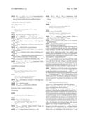
[0009]FIG. 1 shows an equivalent circuit diagram for lead accumulators.
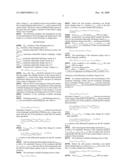
[0010]FIG. 2 shows a structural illustration of the power prediction.
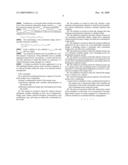
[0011]FIG. 3 shows a flow chart for the prediction of discharge power.
[0012]FIG. 4 shows a flow chart of the prediction of the charge power.
DETAILED DESCRIPTION OF EXAMPLE EMBODIMENTS
Mathematical Model of the Energy Store
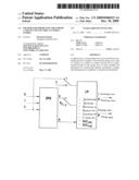
[0013]FIG. 1 shows the equivalent circuit diagram of a lead accumulator, used for the power prediction. The counting direction of battery current IBatt was chosen to be positive for charging and negative for discharging.
Voltages:
[0014]UBatt=Terminal voltage of the battery [0015]URi=Ohmic voltage drop [0016]Uc0=static voltage (˜average acid concentration in the battery, a measure for the charge state) [0017]Uk=concentration polarization (˜deviation of the acid concentration at the point of reaction from the average value in the battery) [0018]UD(IBatt, TBatt, Uc0)=steady state charge transfer polarization, as a function of the battery current and the acid temperature, and in the charge case also the static voltage
Equivalent Circuit Diagram Components:
[0018] [0019]Ri(UC0, Uk, TBatt)=Ohmic internal resistance, as a function of the static voltage, the concentration polarization and the acid temperature [0020]Rk(UC0, TBatt)=acid diffusion resistance, as a function of the static voltage and the acid temperature [0021]τk=Rk*Ck=time constant of acid diffusion (is assumed to be constant in the order of magnitude of 10 min) [0022]RD, discharging(IBatt, TBatt)=current-dependent and temperature-dependent resistance of the charge transfer polarization during discharge [0023]RD, Charging(IBatt, TBatt, UC0)=current-dependent, temperature-dependent and static voltage-dependent resistance of charge transfer polarization during charging
Characteristics Maps and Parameters:
Ohmic Internal Resistance:
[0024]Ri(UC0,Uk,TBatt)=Ri0(TBatt)*(1+Ri- ,fakt*(UC0max-UC0)/(UC0+Uk-U.sub.e,grenz))
where [0025]Ri0 (TBatt)=Ri025/(1+TKLfakt*(TBatt-25° C.) [0026]U.sub.e,grenz=max (UC0,grenz, UC0,Eis(TBatt)) [0027]UC0,Eis(TBatt)=UC0,Eis0+C1,Eis*TBatt+C.sub- .2,Eis*TBatt+C3,Eis*TBatt3 [0028]Ri025=Ohmic internal resistance at full charge and TBatt=25° C. [0029]TKLfakt=Temperature coefficient of the battery conductivity [0030]Ri, fakt=characteristics map parameters [0031]UC0max=maximum static voltage of the completely charged battery [0032]U.sub.e,grenz=minimum static voltage at discharge conclusion [0033]UC0,grenz=minimum static voltage at discharge conclusion without consideration of battery icing [0034]UC0,Eis(TBatt)=temperature-dependent static voltage limit for battery icing (icing characteristics line) [0035]UC0,Eis0, C1,Eis, C2,Eis, C3,Eis=parameters of the icing characteristics line
Acid Diffusion Resistance
[0036]Rk(UC0,TBatt)=Rk0(TBatt)*(1+Rk,fakt1*(- UC0max-UC0)+Rk,fakt2*(UC0max-UC0) 2)
where
Rk0(TBatt)=Rk025*exp(-(E.sub.Rk0/J)/8.314*(1/(273.15+TBatt/° C.)-1/298.15)) (Arrhenius approach) [0037]Rk025=acid diffusion resistance at full charge and TBatt=25° C. [0038]E.sub.Rk0=activation energy [0039]Rk,fakt1Rk,fakt2=polynomial coefficients
Stationary Charge Transfer Polarization
Discharging:
[0040]UD,Ela(IBatt,TBatt)=UD0,Ela(TBatt)*ln (IBatt/ID0,Ela),
where [0041]ID0,Ela=-1A, IBatt<ID0,Ela
[0041]UC0,Eis(TBatt)=UD025,Ela*(1+TK.sub.UD01*(TBatt-2- 5° C.)+TK.sub.UD02*(TBatt-25° C.)2+ . . . TK.sub.UD03*(TBatt-25° C.)3) [0042]UD025,Ela=stationary charge transfer voltage at IBatt=e*ID0,Ela und TBatt=25° C. [0043]ID0,Ela=charge transfer current for UD=0V [0044]TK.sub.UD01, TK.sub.UD02, TK.sub.UD03=Temperature coefficients first, second and third order of charge transfer polarization
Charging:
[0045]UD,Lad(IBatt,TBatt,UC0)=UD0,Lad(TBatt)- *sqrt(IBatt/ID0,Lad*(UC0max-UC0min)/(UC0max-U.sub- .C0))
where [0046]ID0,Lad=1A, IBatt>0A
[0046]UD0,Lad(TBatt)=UD025,Lad* . . . sqrt exp(-(EuD0,Lad/J)/8.314*(1/298.15-1/(273.15+TBatt/° C.))))) [0047]UD025,Lad=stationary charge transfer voltage at IBatt=ID0,Lad, TBatt=25° C. und UC0=UC0min [0048]EuD0,Lad=activation energy [0049]UC0min=minimum static voltage of the completely discharged battery
[0050]Required state variables and parameters for the prediction of discharge and charge power
[0051]The currently available discharge and charge power is able to be predicted with the aid of the above-mentioned model equations, and under the assumption that the state variables and the parameters of the prediction model correspond to those of the actual battery. The variables being looked for may be determined, for instance, by comparison of the model in light of the measured variables current, voltage and temperature, using a Kalman filter.
[0052]For the prediction of the current discharge/charge power, in each case the current state variables of the prediction model, that is, the static voltage UC0 and the concentration polarization have to be known. Therefore, the state estimator has to ascertain at least the state vector x=[UC0, Uk]. An improvement in the power estimation is made possible by additional estimation of charge transfer polarization UD.
[0053]Furthermore, at least the strongly aging-dependent parameters of the prediction model have to be adjusted. These are the characteristics curve parameters Ri025 and UC0,grenz of the Ohmic internal resistance and the acid diffusion resistance Rk025 at full charge and TBatt=25° C. The prediction may be further improved by the additional adjustment of characteristics curve parameters UD025,Ela and UD025,Lad of the charge transfer polarization. Using this, one best obtains the parameter vector
p=[Ri025,UC0,grenz, Rk025,UD025,Ela, UD025,Lad]
with the aid of suitable parameter estimation methods.
[0054]Prediction of the maximum available discharge power and charge power (power predictor)
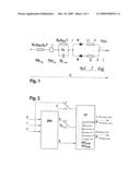
[0055]FIG. 2 shows the structure in principle of the power prediction. A state estimator and parameter estimator (e.g., a Kalman filter) estimates continuously the current state variables required for the power prediction and the parameters of the electrical energy store by which the prediction model is initiated. Subsequently, with the aid of the model equations and the specifications for the duration of the discharge/charge pulse, the admissible minimum and maximum battery voltage, the admissible maximum discharge and charge current as well as the minimum and maximum charge state, one may calculate the available discharge/charge power.
[0056]If one wants to find out the available charge/discharge power at other temperatures (e.g., a cold start temperature of -18° C. or a nominal temperature of 25° C.) and/or charge states (e.g., full charge) as the current one, TBatt and static voltage UC0 are initiated in the power predictor using the corresponding specified values TBatt0 and x0 instead of the current values. The power values ascertained in this manner at the same time also supply a measure for the battery's aging (SOH=state of health).
[0057]The following conditions and assumptions are met for the determination of the discharge and charge power with respect to a constant current discharge or charge pulse:
DEFINITIONS
[0058]ΔtEla=duration of the discharge pulse in sΔtLad=duration of the discharge pulse in sUEla,min=minimal admissible vehicle electrical system voltage in VULad,max=maximum admissible battery(-charging) voltage in VIEla,max=maximum admissible discharge current in AILad,max=maximum admissible charge current in ASOCmin=minimum admissible charge state in %SOCmax=minimum admissible charge state in %
[0059]Using the SOC definition of static voltage UC0:
SOC=100*(UC0-UC0,min)/(UC0,max-UC0,min)
[0060]ΔtEla and =ΔtdLad should be selected to be so small that the charge state change because of the current pulse is negligible (UC0=const) and so large, that the charge transfer polarization during the current pulse assumes its stationary value (order of magnitude 1-10 s).
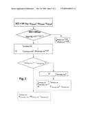
[0061]What is shown is the sequence of the power prediction, or rather, the sequence to the prediction of the maximum available discharge and charge power in two flow charts. The sequence of the power prediction, in this instance, is shown separately for discharge and charge power in FIGS. 3 and 4.
[0062]Prediction of the maximum available discharge power
[0063]Discharge current IEla,pred and discharge power PEla,pred are ascertained by determining the zero value of
!
UBatt,Modell(IEla,pred)-UEla,min=0
the battery voltage UBatt,Modell(IEla,pred), that sets in at the end of the discharge current pulse of duration ΔtEla being calculated with the aid of the prediction model that has already been described:
UBatt,Modell(IEla,pred)=UC0,pred+Uk,pred+ . . . Ri(UC0,pred,Uk,pred,TBatt)*IEla,pred+Uk,pre- d+UD,Ela(IEla,pred,TBatt)
where [0064]UC0,pred=UC0 (=> charge state change by current pulse ignored)
[0064]Uk,pred=Rk(UC0,pred,TBatt)*IEla,pred+ . . . (Uk-Rk(UC0,pred,TBatt)*IEla,pred)*exp(-Δt.- sub.Ela/τk)
(=> solution of the differential equation for the RC-member Rk∥Ck)
[0065]After inserting the relationships mentioned, IEla,pred is able to be calculated. Because of the nonlinear function UD,Ela(IEla,pred,TBatt), this can only be done numerically with the aid of a null search method, such as a method of false positions.
[0066]The maximum available discharge power is then
PEla,pred=UEla,min*IEla,pred
[0067]Before the null position calculation one should check whether there is a solution IEla,pred<0A in the first place. To do this, it is tested whether the condition:
UBatt,Modell(IEla,pred=0A,ΔtEla=0s)=UC0+Uk&- gt;UEla,min is satisfied.
[0068]If not, IEla,pred=0A and PEla,pred=0W are output.
[0069]Furthermore, one should check whether the definitions for the maximum admissible discharge current IEla,max and the minimum charge state SOCmin are being maintained.
[0070]If |IEla,pred|>|IEla,max|, IEla,pred is set=IEla,max, und UBatt,Modell(IEla,max) is calculated, so that for the maximum discharge power,
PEla,pred=UBatt,Modell(IEla,max)*IEla,max
results.
[0071]The maintaining of the minimum charge state is checked using the condition:
SOC=100*(UC0-UC0,min)/(UC0,max-UC0,min)>SOCmin
[0072]If the condition is not satisfied, IEla,pred=0A und PEla,pred=0W are output.
[0073]It is to be observed that
SOCmin>SOCgrenz=100*(U.sub.e,grenz-UC0,min)/(UC0,ma- x-UC0,min) has to be specified (see formula for Ri in section 2.4.1).
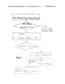
Prediction of the Maximum Available Charge Power
[0074]In a manner equivalent to the ascertainment of the maximum discharge current and the maximum discharge power, maximum charge current IEla,pred and the maximum charge power PLad,pred are ascertained by determining the null position of
!
UBatt,Modell(IEla,pred)-UEla,min=0
the battery voltage UBatt,Modell(IEla,pred), that sets in at the end of the charge current pulse of duration ΔtLad, being calculated again with the aid of the prediction model that has already been described:
UBatt,Modell(ILad,pred)=UC0,pred+Uk,pred+Ri(U.sub- .C0,pred,Uk,pred,TBatt)*ILad,pred+Uk,pred+ . . . UD,Lad(ILad,pred,TBatt, UC0,pred)
where: [0075]UC0,pred=UC0 (=>charge state change by current pulse ignored)
[0075]Uk,pred=Rk(UC0,pred,TBatt)*ILad,pred+ . . . (Uk-Rk(UC0,pred,TBatt)*ILad,pred)*exp(-Δt.- sub.Lad/τk)
(=> solution of the differential equation for the RC-member Rk∥Ck)
[0076]After inserting the relationships mentioned, IEla,pred is able to be calculated. Because of the nonlinear function UD,Lad(ILad,pred,TBatt,UC0,pred), this can again only be done numerically with the aid of a null search method, such as a method of false positions.
[0077]The maximum available discharge power is then
PLad,pred=ULad,max*ILad,pred
[0078]Before the null position calculation one should check whether there is a solution to ILad,pred>0A at all. To do this, it is tested whether the condition:
UBatt,Modell(ILad,pred=0A,ΔtLad=0S)=UC0+Uk&- lt;ULad,max is satisfied.
[0079]If not, ILad,pred=0A and PLad,pred=0W are output.
[0080]Furthermore, one should check whether the definitions of the maximum admissible charge current ILad,max and the maximum charge state SOCmax are being maintained.
[0081]If |ILad,pred|>|ILad,max|, ILad,pred is set=ILad,max and UBatt,Modell(ILad,max) is calculated, so that for the maximum charge power one obtains:
PEla,pred=UBatt,Modell(IEla,max)*IEla,max
[0082]The maintaining of the maximum charge state is checked using the condition:
SOC=100*(UC0-UC0,min)/(UC0,max-UC0,min)<SOCmax- ≦100%
[0083]If the condition is not satisfied, ILad,pred=0A und PLad,pred=0W are output.
[0084]The methods described may be modified in a suitable manner, if necessary. They preferably run in a suitably equipped control device, for instance, a control unit for battery state detection to which the battery is connected, or a vehicle electrical system manager in a vehicle.
[0085]A further possibility for their application is in an IBS (intelligent battery sensor) and/or in body computers, or as software module within the scope of an electrical battery management.
Claims:
1-11. (canceled)
12. A method for predicting the power capacity of an electrical energy store, comprising:forming a mathematical model of the energy store;continuously adjusting state variables and parameters of the model; andpredicting a maximum charge and a discharge power using the model.
13. The method as recited in claim 12, wherein relevant influential variables including at least one of temperature, charge state, Ohmic internal resistance, polarizations, acid stratification, age, and icing, are taken into consideration in the model.
14. The method as recited in claim 12, wherein a state estimator and parameter estimator is used for power prediction which continuously estimates currently required state variables.
15. The method as recited in claim 14, wherein the state estimator and parameter estimator is a Kalman filter.
16. The method as recited in claim 12, wherein at least one of a maximum admissible charge voltage and a minimum vehicle electrical system voltage, are taken into consideration in the model.
17. The method as recited in claim 16, wherein additional definitions for the at least one of an admissible maximum charge, a discharge current, a minimum, and a maximum charge state, are taken into consideration.
18. The method as recited in claim 12, wherein at least one of a currently available charge, and a discharge power are determined using the model.
19. The method as recited in claim 16, wherein at least one of a charge power and a discharge power to be expected at any at least one of specifiable temperatures, and charge states are determined using the model.
20. The method as recited in claim 12, wherein at least one of a charge power and a discharge power ascertained with reference to a fixed specified temperature are used as a measure for an aging of the energy store.
21. The method as recited in claim 12, wherein the energy store is a battery for a vehicle.
22. A device for predicting a power capacity of an electrical energy store, comprising:a control device adapted to form a mathematical model of the energy store, continuously adjust state variables and parameters of the model, and predict a maximum charge and a discharge power using the model.
23. The device as recited in claim 22, wherein the control device includes a control unit, or is a component of an intelligent battery sensor or a body computer or a component of a software module for an electrical battery management.
Description:
FIELD OF THE INVENTION
[0001]The present invention relates to a method for predicting the power capacity of electrical energy stores. In particular, variables are ascertained of an electrical energy store or power store for a motor vehicle.
BACKGROUND INFORMATION
[0002]Information about current, maximally available discharge power of the battery, that is as exact as possible, is important for electrical energy management in vehicles. This applies especially to electric and hybrid vehicles, and vehicles having start and stop function and recuperative intervention, in which the current, maximally available discharge power of the electric energy store, provided for the engine start, electrical drive, and for the supply of other electrical users, as well as the currently maximally available charge power of the electrical energy store used for the feedback of the braking energy are of decisive importance.
[0003]Various methods are known for ascertaining the power capacity of electrical energy stores. Most methods are limited to the determination of the available discharge power. German Patent Application No. DE 103 01 823, for example, describes the discharge power capacity is evaluated in light of a voltage response, precalculated with the aid of a model, to a specified load current profile. However, this attempt does not yet deliver any reply to the question as to what maximum power the energy store is able to supply at a specified minimum admissible vehicle electrical system voltage.
[0004]For the evaluation of the recuperation capacity, the charge power capacity and the charge acceptance of an energy store, methods are provided that are supported by characteristics maps as a function of the charge state and the temperature and/or the impedance of the energy store. German Patent Application No. DE 198 49 055 describes such methods, for example. However, further limiting factors for the charge power capacity, such as polarization, acid stratification or icing of the energy store, especially of a lead battery, are not considered.
SUMMARY
[0005]By contrast, an example method according to the present invention may make possible an improved determination of the relevant variables of the energy store. This advantage is achieved with the aid of a mathematical model of the energy store, whose state variables and parameters are continuously adapted. This makes possible an accurate prediction of the maximum charge and discharge power of the electrical energy store, particularly of a lead accumulator used in a motor vehicle, by taking into consideration all the relevant influential variables, such as the temperature, the charge state, the Ohmic internal resistance, polarizations, acid stratification, aging and icing.
[0006]The example methods may advantageously make possible the model-based prediction of the current maximum charge and discharge power of an electrical energy store, particularly under consideration of the admissible maximum charge voltage and the minimum vehicle electrical system voltage. In an advantageous refinement, additional specifications for the admissible maximum charge and/or discharge current and/or the minimum or maximum charge state may be taken into consideration.
[0007]Besides the prediction of the current available charge and discharge power, the example method according to the present invention is also in a position, in a particularly advantageous manner, of determining the charge and discharge power to be expected at any specifiable temperatures and charge states. The available charge power of a battery, having an SOC (state of charge)=50% for a cold start at -18° C., may be ascertained, for example. The charge and discharge power referred to a specified fixed temperature and a specified charge state may also be used as a measure of the battery aging SOH (state of health).
BRIEF DESCRIPTION OF THE DRAWINGS
[0008]The present invention is represented in the figures and explained in greater detail below.
[0009]FIG. 1 shows an equivalent circuit diagram for lead accumulators.
[0010]FIG. 2 shows a structural illustration of the power prediction.
[0011]FIG. 3 shows a flow chart for the prediction of discharge power.
[0012]FIG. 4 shows a flow chart of the prediction of the charge power.
DETAILED DESCRIPTION OF EXAMPLE EMBODIMENTS
Mathematical Model of the Energy Store
[0013]FIG. 1 shows the equivalent circuit diagram of a lead accumulator, used for the power prediction. The counting direction of battery current IBatt was chosen to be positive for charging and negative for discharging.
Voltages:
[0014]UBatt=Terminal voltage of the battery [0015]URi=Ohmic voltage drop [0016]Uc0=static voltage (˜average acid concentration in the battery, a measure for the charge state) [0017]Uk=concentration polarization (˜deviation of the acid concentration at the point of reaction from the average value in the battery) [0018]UD(IBatt, TBatt, Uc0)=steady state charge transfer polarization, as a function of the battery current and the acid temperature, and in the charge case also the static voltage
Equivalent Circuit Diagram Components:
[0018] [0019]Ri(UC0, Uk, TBatt)=Ohmic internal resistance, as a function of the static voltage, the concentration polarization and the acid temperature [0020]Rk(UC0, TBatt)=acid diffusion resistance, as a function of the static voltage and the acid temperature [0021]τk=Rk*Ck=time constant of acid diffusion (is assumed to be constant in the order of magnitude of 10 min) [0022]RD, discharging(IBatt, TBatt)=current-dependent and temperature-dependent resistance of the charge transfer polarization during discharge [0023]RD, Charging(IBatt, TBatt, UC0)=current-dependent, temperature-dependent and static voltage-dependent resistance of charge transfer polarization during charging
Characteristics Maps and Parameters:
Ohmic Internal Resistance:
[0024]Ri(UC0,Uk,TBatt)=Ri0(TBatt)*(1+Ri- ,fakt*(UC0max-UC0)/(UC0+Uk-U.sub.e,grenz))
where [0025]Ri0 (TBatt)=Ri025/(1+TKLfakt*(TBatt-25° C.) [0026]U.sub.e,grenz=max (UC0,grenz, UC0,Eis(TBatt)) [0027]UC0,Eis(TBatt)=UC0,Eis0+C1,Eis*TBatt+C.sub- .2,Eis*TBatt+C3,Eis*TBatt3 [0028]Ri025=Ohmic internal resistance at full charge and TBatt=25° C. [0029]TKLfakt=Temperature coefficient of the battery conductivity [0030]Ri, fakt=characteristics map parameters [0031]UC0max=maximum static voltage of the completely charged battery [0032]U.sub.e,grenz=minimum static voltage at discharge conclusion [0033]UC0,grenz=minimum static voltage at discharge conclusion without consideration of battery icing [0034]UC0,Eis(TBatt)=temperature-dependent static voltage limit for battery icing (icing characteristics line) [0035]UC0,Eis0, C1,Eis, C2,Eis, C3,Eis=parameters of the icing characteristics line
Acid Diffusion Resistance
[0036]Rk(UC0,TBatt)=Rk0(TBatt)*(1+Rk,fakt1*(- UC0max-UC0)+Rk,fakt2*(UC0max-UC0) 2)
where
Rk0(TBatt)=Rk025*exp(-(E.sub.Rk0/J)/8.314*(1/(273.15+TBatt/° C.)-1/298.15)) (Arrhenius approach) [0037]Rk025=acid diffusion resistance at full charge and TBatt=25° C. [0038]E.sub.Rk0=activation energy [0039]Rk,fakt1Rk,fakt2=polynomial coefficients
Stationary Charge Transfer Polarization
Discharging:
[0040]UD,Ela(IBatt,TBatt)=UD0,Ela(TBatt)*ln (IBatt/ID0,Ela),
where [0041]ID0,Ela=-1A, IBatt<ID0,Ela
[0041]UC0,Eis(TBatt)=UD025,Ela*(1+TK.sub.UD01*(TBatt-2- 5° C.)+TK.sub.UD02*(TBatt-25° C.)2+ . . . TK.sub.UD03*(TBatt-25° C.)3) [0042]UD025,Ela=stationary charge transfer voltage at IBatt=e*ID0,Ela und TBatt=25° C. [0043]ID0,Ela=charge transfer current for UD=0V [0044]TK.sub.UD01, TK.sub.UD02, TK.sub.UD03=Temperature coefficients first, second and third order of charge transfer polarization
Charging:
[0045]UD,Lad(IBatt,TBatt,UC0)=UD0,Lad(TBatt)- *sqrt(IBatt/ID0,Lad*(UC0max-UC0min)/(UC0max-U.sub- .C0))
where [0046]ID0,Lad=1A, IBatt>0A
[0046]UD0,Lad(TBatt)=UD025,Lad* . . . sqrt exp(-(EuD0,Lad/J)/8.314*(1/298.15-1/(273.15+TBatt/° C.))))) [0047]UD025,Lad=stationary charge transfer voltage at IBatt=ID0,Lad, TBatt=25° C. und UC0=UC0min [0048]EuD0,Lad=activation energy [0049]UC0min=minimum static voltage of the completely discharged battery
[0050]Required state variables and parameters for the prediction of discharge and charge power
[0051]The currently available discharge and charge power is able to be predicted with the aid of the above-mentioned model equations, and under the assumption that the state variables and the parameters of the prediction model correspond to those of the actual battery. The variables being looked for may be determined, for instance, by comparison of the model in light of the measured variables current, voltage and temperature, using a Kalman filter.
[0052]For the prediction of the current discharge/charge power, in each case the current state variables of the prediction model, that is, the static voltage UC0 and the concentration polarization have to be known. Therefore, the state estimator has to ascertain at least the state vector x=[UC0, Uk]. An improvement in the power estimation is made possible by additional estimation of charge transfer polarization UD.
[0053]Furthermore, at least the strongly aging-dependent parameters of the prediction model have to be adjusted. These are the characteristics curve parameters Ri025 and UC0,grenz of the Ohmic internal resistance and the acid diffusion resistance Rk025 at full charge and TBatt=25° C. The prediction may be further improved by the additional adjustment of characteristics curve parameters UD025,Ela and UD025,Lad of the charge transfer polarization. Using this, one best obtains the parameter vector
p=[Ri025,UC0,grenz, Rk025,UD025,Ela, UD025,Lad]
with the aid of suitable parameter estimation methods.
[0054]Prediction of the maximum available discharge power and charge power (power predictor)
[0055]FIG. 2 shows the structure in principle of the power prediction. A state estimator and parameter estimator (e.g., a Kalman filter) estimates continuously the current state variables required for the power prediction and the parameters of the electrical energy store by which the prediction model is initiated. Subsequently, with the aid of the model equations and the specifications for the duration of the discharge/charge pulse, the admissible minimum and maximum battery voltage, the admissible maximum discharge and charge current as well as the minimum and maximum charge state, one may calculate the available discharge/charge power.
[0056]If one wants to find out the available charge/discharge power at other temperatures (e.g., a cold start temperature of -18° C. or a nominal temperature of 25° C.) and/or charge states (e.g., full charge) as the current one, TBatt and static voltage UC0 are initiated in the power predictor using the corresponding specified values TBatt0 and x0 instead of the current values. The power values ascertained in this manner at the same time also supply a measure for the battery's aging (SOH=state of health).
[0057]The following conditions and assumptions are met for the determination of the discharge and charge power with respect to a constant current discharge or charge pulse:
DEFINITIONS
[0058]ΔtEla=duration of the discharge pulse in sΔtLad=duration of the discharge pulse in sUEla,min=minimal admissible vehicle electrical system voltage in VULad,max=maximum admissible battery(-charging) voltage in VIEla,max=maximum admissible discharge current in AILad,max=maximum admissible charge current in ASOCmin=minimum admissible charge state in %SOCmax=minimum admissible charge state in %
[0059]Using the SOC definition of static voltage UC0:
SOC=100*(UC0-UC0,min)/(UC0,max-UC0,min)
[0060]ΔtEla and =ΔtdLad should be selected to be so small that the charge state change because of the current pulse is negligible (UC0=const) and so large, that the charge transfer polarization during the current pulse assumes its stationary value (order of magnitude 1-10 s).
[0061]What is shown is the sequence of the power prediction, or rather, the sequence to the prediction of the maximum available discharge and charge power in two flow charts. The sequence of the power prediction, in this instance, is shown separately for discharge and charge power in FIGS. 3 and 4.
[0062]Prediction of the maximum available discharge power
[0063]Discharge current IEla,pred and discharge power PEla,pred are ascertained by determining the zero value of
!
UBatt,Modell(IEla,pred)-UEla,min=0
the battery voltage UBatt,Modell(IEla,pred), that sets in at the end of the discharge current pulse of duration ΔtEla being calculated with the aid of the prediction model that has already been described:
UBatt,Modell(IEla,pred)=UC0,pred+Uk,pred+ . . . Ri(UC0,pred,Uk,pred,TBatt)*IEla,pred+Uk,pre- d+UD,Ela(IEla,pred,TBatt)
where [0064]UC0,pred=UC0 (=> charge state change by current pulse ignored)
[0064]Uk,pred=Rk(UC0,pred,TBatt)*IEla,pred+ . . . (Uk-Rk(UC0,pred,TBatt)*IEla,pred)*exp(-Δt.- sub.Ela/τk)
(=> solution of the differential equation for the RC-member Rk∥Ck)
[0065]After inserting the relationships mentioned, IEla,pred is able to be calculated. Because of the nonlinear function UD,Ela(IEla,pred,TBatt), this can only be done numerically with the aid of a null search method, such as a method of false positions.
[0066]The maximum available discharge power is then
PEla,pred=UEla,min*IEla,pred
[0067]Before the null position calculation one should check whether there is a solution IEla,pred<0A in the first place. To do this, it is tested whether the condition:
UBatt,Modell(IEla,pred=0A,ΔtEla=0s)=UC0+Uk&- gt;UEla,min is satisfied.
[0068]If not, IEla,pred=0A and PEla,pred=0W are output.
[0069]Furthermore, one should check whether the definitions for the maximum admissible discharge current IEla,max and the minimum charge state SOCmin are being maintained.
[0070]If |IEla,pred|>|IEla,max|, IEla,pred is set=IEla,max, und UBatt,Modell(IEla,max) is calculated, so that for the maximum discharge power,
PEla,pred=UBatt,Modell(IEla,max)*IEla,max
results.
[0071]The maintaining of the minimum charge state is checked using the condition:
SOC=100*(UC0-UC0,min)/(UC0,max-UC0,min)>SOCmin
[0072]If the condition is not satisfied, IEla,pred=0A und PEla,pred=0W are output.
[0073]It is to be observed that
SOCmin>SOCgrenz=100*(U.sub.e,grenz-UC0,min)/(UC0,ma- x-UC0,min) has to be specified (see formula for Ri in section 2.4.1).
Prediction of the Maximum Available Charge Power
[0074]In a manner equivalent to the ascertainment of the maximum discharge current and the maximum discharge power, maximum charge current IEla,pred and the maximum charge power PLad,pred are ascertained by determining the null position of
!
UBatt,Modell(IEla,pred)-UEla,min=0
the battery voltage UBatt,Modell(IEla,pred), that sets in at the end of the charge current pulse of duration ΔtLad, being calculated again with the aid of the prediction model that has already been described:
UBatt,Modell(ILad,pred)=UC0,pred+Uk,pred+Ri(U.sub- .C0,pred,Uk,pred,TBatt)*ILad,pred+Uk,pred+ . . . UD,Lad(ILad,pred,TBatt, UC0,pred)
where: [0075]UC0,pred=UC0 (=>charge state change by current pulse ignored)
[0075]Uk,pred=Rk(UC0,pred,TBatt)*ILad,pred+ . . . (Uk-Rk(UC0,pred,TBatt)*ILad,pred)*exp(-Δt.- sub.Lad/τk)
(=> solution of the differential equation for the RC-member Rk∥Ck)
[0076]After inserting the relationships mentioned, IEla,pred is able to be calculated. Because of the nonlinear function UD,Lad(ILad,pred,TBatt,UC0,pred), this can again only be done numerically with the aid of a null search method, such as a method of false positions.
[0077]The maximum available discharge power is then
PLad,pred=ULad,max*ILad,pred
[0078]Before the null position calculation one should check whether there is a solution to ILad,pred>0A at all. To do this, it is tested whether the condition:
UBatt,Modell(ILad,pred=0A,ΔtLad=0S)=UC0+Uk&- lt;ULad,max is satisfied.
[0079]If not, ILad,pred=0A and PLad,pred=0W are output.
[0080]Furthermore, one should check whether the definitions of the maximum admissible charge current ILad,max and the maximum charge state SOCmax are being maintained.
[0081]If |ILad,pred|>|ILad,max|, ILad,pred is set=ILad,max and UBatt,Modell(ILad,max) is calculated, so that for the maximum charge power one obtains:
PEla,pred=UBatt,Modell(IEla,max)*IEla,max
[0082]The maintaining of the maximum charge state is checked using the condition:
SOC=100*(UC0-UC0,min)/(UC0,max-UC0,min)<SOCmax- ≦100%
[0083]If the condition is not satisfied, ILad,pred=0A und PLad,pred=0W are output.
[0084]The methods described may be modified in a suitable manner, if necessary. They preferably run in a suitably equipped control device, for instance, a control unit for battery state detection to which the battery is connected, or a vehicle electrical system manager in a vehicle.
[0085]A further possibility for their application is in an IBS (intelligent battery sensor) and/or in body computers, or as software module within the scope of an electrical battery management.
User Contributions:
Comment about this patent or add new information about this topic:
Images included with this patent application:
 |  |
 |  |
 |  |
 |
| New patent applications in this class: | |
| Date | Title |
|---|---|
| 2022-05-05 | Management method, management device, management system and non-transitory storage medium |
| 2022-05-05 | Measurement system and method for determining a status of a power system in a vehicle using the measurement system |
| 2022-05-05 | Battery model estimation based on battery terminal voltage and current transient due to load powered from the battery |
| 2019-05-16 | Electrical control system |
| 2018-01-25 | Battery management system |
| New patent applications from these inventors: | |
| Date | Title |
|---|---|
| 2015-11-26 | Method and system for starting a motor vehicle |
| 2011-09-01 | Method for calculating the charge state of a battery |
| 2010-03-18 | Method for determining the battery capacity with the aid of capacity-dependent parameters |
| Top Inventors for class "Data processing: measuring, calibrating, or testing" | |
| Rank | Inventor's name |
|---|---|
| 1 | Lowell L. Wood, Jr. |
| 2 | Roderick A. Hyde |
| 3 | Shelten Gee Jao Yuen |
| 4 | James Park |
| 5 | Chih-Kuang Chang |