Patent application title: SHOE
Inventors:
Chia-Hung Liao (Tu-Cheng, TW)
Assignees:
HON HAI PRECISION INDUSTRY CO., LTD.
IPC8 Class: AA43B1300FI
USPC Class:
36103
Class name: Boots, shoes, and leggings boots and shoes having particular outsole (e.g., sectional sole)
Publication date: 2009-11-26
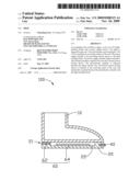
Patent application number: 20090288315
Inventors list |
Agents list |
Assignees list |
List by place |
Classification tree browser |
Top 100 Inventors |
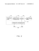
Top 100 Agents |
Top 100 Assignees |
Usenet FAQ Index |
Documents |
Other FAQs |
Patent application title: SHOE
Inventors:
Chia-Hung Liao
Agents:
PCE INDUSTRY, INC.;ATT. Steven Reiss
Assignees:
HON HAI PRECISION INDUSTRY CO., LTD.
Origin: CITY OF INDUSTRY, CA US
IPC8 Class: AA43B1300FI
USPC Class:
36103
Patent application number: 20090288315
Abstract:
An exemplary shoe includes a upper, a sole, an LED (light-emitting diode)
and a power supply device. The upper is disposed on the sole. The sole
includes a receiving space. The LED is installed on an outside surface of
the sole. The power supply module is for providing electric power to the
light emitting diode. The power supply module further includes a
piezoelectric member coupled to the sole and a electric power storing
device. The piezoelectric member is disposed between the upper and the
sole. The electric power storing device is received in the receiving
space of the sole and electrically coupled between the piezoelectric
member and the light emitting diode.Claims:
1. A shoe, comprising:a sole;an upper disposed on the sole;a light
emitting diode installed on an outside surface of the sole;a power supply
module for providing electric power to the light emitting diode, the
power supply module comprising a piezoelectric member coupled to the sole
and an electric power storing device, the piezoelectric member being
configured for generating electric power, the electric power storing
device being electrically coupled between the piezoelectric member and
the light emitting diode.
2. The shoe according to claim 1, wherein the light emitting diode is installed on a front outside surface of the sole.
3. The shoe according to claim 1, wherein the electric power storing device comprises a capacitor or a rechargeable battery.
4. The shoe according to claim 1, wherein the power supply module further comprises a switch electrically coupled between the electric power storing device and the light emitting diode.
5. The shoe according to claim 4, wherein the power supply module further comprises a detecting device, the detecting device having a predetermined standard brightness value stored therein, the detecting device being configured for sensing a brightness of the exterior environment and comparing the detected brightness with the predetermined standard brightness, and controlling the switch to open or close according to the comparison result.
6. The shoe according to claim 5, wherein the detecting device further comprises a sensing cell and a comparing cell, the sensing cell being configured for sensing the brightness of the exterior environment, the comparing cell being configured for comparing the detected brightness with the predetermined standard brightness thereby controlling the switch to open or close according to the comparison result.
7. The shoe according to claim 1, wherein the piezoelectric member is made of a material selected from a group consisting of barium titanate, lithium germanium oxide and polyvinylidene fluoride.
8. A shoe comprising:a sole having a heel portion;an upper attached on the sole;a light emitting member;a piezoelectric member embedded in the heel portion for generating electric power, andan electric power storing device configured for storing the electric power and being electrically coupled between the piezoelectric member and the light emitting member.
Description:
BACKGROUND
[0001]1. Technical Field
[0002]The present disclosure generally relates to shoes, particularly, to a shoe with light emitting diodes.
[0003]2. Discussion of Related Art
[0004]Nowadays, various type of shoes may include light emitting diodes embedded for aesthetic or safety reasons. The light emitting diodes are usually powered by battery. However, the electric power of the battery will easily run out overtime and the old battery must be replaced by new ones. Therefore, such shoes are not environmentally friendly.
[0005]Therefore, what is needed is a shoe that overcomes the described limitations.
BRIEF DESCRIPTION OF THE DRAWINGS
[0006]Many aspects of the disclosed shoe can be better understood with reference to the following drawings. The components in the drawings are not necessarily drawn to scale, the emphasis instead being placed upon clearly illustrating the principles of the present shoe, wherein:
[0007]FIG. 1 is a cross-sectional view of a shoe, according to an exemplary embodiment; and
[0008]FIG. 2 is a block diagram showing a power supply module of the shoe in FIG. 1.
DETAILED DESCRIPTION
[0009]Reference will now be made to the drawings to describe the embodiments of the shoe, in detail.
[0010]Referring to FIG. 1, a shoe 100, according to a first embodiment, includes a upper 10, a sole 20, a light emitting diode (LED) 40 and a power supply module 60.
[0011]The upper 10 is disposed on the sole 20.
[0012]The sole 20 includes an internal receiving space 22. In an exemplary embodiment, the receiving space 22 is defined between the upper 10 and the sole 20 and communicates with a surface of the upper 10. The receiving space 22 can also be defined in an interior of the sole 20 without communicating with any surface of the upper 10.
[0013]The LED 40 is installed on an outside surface of the sole 20. In an exemplary embodiment, the LED 40 is installed on a front outside surface of the sole 20, thereby illuminating the area in front of the shoe.
[0014]The power supply module 60 is configured for providing electric power to the LED 40. The power supply module 60 includes a piezoelectric member 62 coupled to the sole 20 and an electric power storing device 64. In an exemplary embodiment, the sole 20 has a heel portion 21 and the piezoelectric member 62 is embedded in the heel portion 21.
[0015]The piezoelectric member 62 is disposed between the upper 10 and the sole 20. The piezoelectric member 62 can be made of barium titanate (BaTiO3), lithium germanium oxide (LiGeO3) or polyvinylidene fluoride (PVDF). When the shoe 100 is in motion (i.e. walking, running, etc), pressures generated by motion will be applied to the piezoelectric member 62. Then, the piezoelectric member 62 will transform the mechanical energy into electric energy and thereby electric power is generated by the piezoelectric member 62. The piezoelectric member 62 will transmit the electric power to the power storing device 64.
[0016]The electric power storing device 64 is received in the receiving space 22 and electrically coupled between the piezoelectric member 62 and the light emitting diode 40. The electric power storing device 64 can be a capacitor, or a rechargeable battery, or other electrical components capable of storing electric power. The electric power storing device 64 is capable of receiving the electric energy transmitted from the piezoelectric member 62 and thereby providing electric power to the LED 40.
[0017]In an exemplary embodiment, a switch 66 is coupled between the electric power storing device 64 and the LED 40. The switch 66 has two status of close and open. Thereby, the switch 66 is capable of being used to control the electric power stored in the electric power storing device 64 whether to be supplied to the LED 40.
[0018]In an exemplary embodiment, the power supply module 60 further comprises a detecting device 68. The detecting device 68 has a predetermined standard brightness value stored therein. The detecting device 68 is configured for detecting a brightness of the exterior environment, comparing the detected brightness with the predetermined standard brightness, and controlling the switch 66 to open or close according to the comparison result.
[0019]On the condition that the brightness value of the exterior environment is lower than the predetermined brightness value, the detecting device 68 controls the switch 66 to open to provide electric power to the LED 40. On the condition that the brightness value of the exterior environment is higher than the predetermined brightness value, the detecting device 68 controls the switch 66 to close to cut off the electric power transmitted to the LED 40.
[0020]In a further exemplary embodiment, the detecting device 68 includes a sensing cell 68a and a comparing cell 68b. The sensing cell 68a is configured for sensing the brightness of the exterior environment. The sensing cell 68a can be a photodiode, or a photometer, or other components capable of sensing light brightness. The comparing cell 68b has the predetermined standard brightness value stored therein. The comparing cell 68b is configured for comparing the detected brightness with the predetermined standard brightness thereby controlling the switch to open or close on the condition that the exterior environment is lower or higher than the predetermined brightness value.
[0021]It is to be said that, the switch 66 can be disposed on an outer surface of the sole 20. Thereby, the switch 66 can be artificially closed or open without depending on the comparison result of the detecting device 68.
[0022]Due to that the shoe 100 are equipped with the piezoelectric member 62 and the electric power storing device 64, mechanical energy generated motions of the shoe 100 can be transformed into electric energy by the piezoelectric member 62, and the transformed electric energy can be stored and transmitted to the LED 40 for use by the electric power storing device 64. Thereby, the shoe 100 is energy-saving and environmentally friendly.
[0023]Finally, it is to be understood that the above-described embodiments are intended to illustrate rather than limit the disclosure. Variations may be made to the embodiments without departing from the spirit of the disclosure as claimed. The above-described embodiment illustrates the scope of the disclosure but do not restrict the scope of the disclosure.
User Contributions:
comments("1"); ?> comment_form("1"); ?>Inventors list |
Agents list |
Assignees list |
List by place |
Classification tree browser |
Top 100 Inventors |
Top 100 Agents |
Top 100 Assignees |
Usenet FAQ Index |
Documents |
Other FAQs |
User Contributions:
Comment about this patent or add new information about this topic:
Images included with this patent application:
 |  |
 |
| New patent applications in this class: | |
| Date | Title |
|---|---|
| 2019-05-16 | Mountain bike shoe sole |
| 2016-06-16 | Articles of footwear |
| 2016-05-12 | Article of footwear with a sole assembly having a bladder element and a guide component and method of manufacturing the article of footwear |
| 2016-04-07 | Sole for a shoe |
| 2016-03-10 | Training footwear |
| New patent applications from these inventors: | |
| Date | Title |
|---|---|
| 2013-06-27 | Voice coil motor having sloped surfaces |
| 2012-05-03 | Auto-focus lens module |
| 2011-03-31 | Autofocus lens module |
| 2011-01-20 | Voice coil motor assembly |
| 2010-11-04 | Shell for housing voice coil motor and voice coil motor module |
| Top Inventors for class "Boots, shoes, and leggings" | |
| Rank | Inventor's name |
|---|---|
| 1 | Frederick J. Dojan |
| 2 | Michael A. Aveni |
| 3 | Perry W. Auger |
| 4 | Sergio Cavaliere |
| 5 | Lee D. Peyton |