Patent application title: MICROSCOPE OBJCTIVE
Inventors:
Renhu Shi (Goettingen, DE)
Werner Kleinschmidt (Adelebsen, DE)
Thomas Bocher (Goettingen, DE)
Assignees:
CARL ZEISS MICROIMAGING GMBH
IPC8 Class: AG02B2102FI
USPC Class:
359656
Class name: Optical: systems and elements lens microscope objective
Publication date: 2009-11-19
Patent application number: 20090284841
a microscope objective with preferably
anti-symmetric lenses or lens groups with an optical magnification of
-100 and a visual field factor of 20.
According to the invention the microscope objective consists of 9 lenses
with 3 cemented elements, starting from the object side (left), a lens
which is almost a hemisphere L1 with positive refractive power, a
meniscus lens L2 with positive refractive power, a two-part cemented
element G1 with positive refractive power, another two-art cemented
element G2 with positive refractive power, a two-part cemented
element G3 with negative refractive power, and finally a meniscus
lens L9 with negative refractive power.
By using cemented elements and lens pairings of the same construction,
production costs can be reduced compared with methods of the prior art
while image contrast is improved.Claims:
1. (canceled)
2. A microscope optical system comprising:a microscope objective including anti-symmetric lenses or lens groups;wherein image defects of the microscope objective, selected from a group consisting of spherical aberration, coma, astigmatism, distortion and a combination of the forgoing, are largely corrected;primary longitudinal chromatic aberration of the microscope objective is corrected;nominal optical magnification of the microscope objective is -100 for a numerical aperture (using oil immersion) of 1.25; andlongitudinal chromatic aberrations of the microscope objective for a secondary spectrum are within the range of a triple depth of focus, and image field flattening of the microscope objective is reduced such that a best focus position on an edge of the field differs by less than two depths of focus from an axial focus position.
3. The microscope optical system as claimed in claim 2 wherein the microscope objective comprises 9 lenses with 3 cemented elements, including starting from an object side, a lens which is almost a hemisphere L1 with positive refractive power, a meniscus lens L2 with positive refractive power, a two-part cemented element G1 with positive refractive power, another two-part cemented element G2 with positive refractive power, a two-part cemented element G3 with negative refractive power, and a meniscus lens L9 with negative refractive power, wherein the lens L1 has a plane surface on the object side and a strongly curved surface on an image side thereof and a center of curvature is located on the object side thereof; the lens L2 is meniscus-shaped and the two centers of curvature are located on the object side thereof; the cemented element G1 including a biconcave lens L3 on an object side thereof and a biconvex lens L4 on an image side thereof; the cemented element G2 including a biconvex lens L4 on an object side thereof and a biconcave lens L5 on an image side thereof; the cemented element G3 comprising two meniscus lenses L7 and L8, and the centers of curvature of all surfaces of L7 and L8 are located on an image side thereof and both lenses L7 and L8 have negative refractive power.
4. The microscope optical system as claimed in claim 3, wherein the cemented elements G1 and G2 of the microscope objective are of identical construction and are built into the microscope objective with mirror symmetry, the lenses L8 and L9 are of identical construction and are built into the microscope objective with mirror symmetry, resulting in three pairs of lenses, L3 and L6; L4 and L5; L8 and L9, each being of identical construction.
5. The microscope optical system as claimed in claim 3, wherein the following ratios of the focal lengths apply:1.9<fL1/fObj.<2.44.5<fL2/fObj<5.720- .2<fG1/fObj<25.720.2<fG2/fObj<25.7-14.7<- ;fG3/fObj<-8.2-31.7<fL9/fObj.<-14.2wherein fObj. is the focal length of the objective.
6. The microscope optical system as claimed in claim 4, wherein the lenses L4 and L5 of identical construction satisfy the following conditions:ne>1.66; andνe>54
7. The microscope optical system as claimed in claim 4, wherein the lenses L8 and L9 of identical construction satisfy the following conditions:ne>1.81; andνe<26
8. The microscope optical system as claimed in claim 2, wherein geometry of the lens L1 satisfies the following conditions: d 3 ≧ r 4 ≧ d 1 NA n 1 2 - NA 2 + d 2 NA n 2 2 - NA 2 + d 3 NA n 3 2 - NA 2 ##EQU00001## whereind1 is the thickness of the cover glass;d2 is the optical working distance;d3, r4 respectively are the center thickness and the radius of curvature of the lens L1;NA is the numerical aperture; andne is the refractive index ve for the Abbe number at the spectral line e=546.07 nm.
9. The microscope optical system as claimed in claim 2, further comprising a tube system having a focal length of 180 mm arranged relative to the objective such that rays which come from an object point are parallel to each other between the objective and the tube lens system.
10. The microscope optical system as claimed in claim 2, further comprising a tube system having a focal length of 200 mm, arranged relative to the objective such that rays which come from an object point are parallel to each other between the objective and the tube lens system and wherein chromatic aberrations of the objective and of the tube lens system are corrected separately from each other.
11. The microscope optical system as claimed in claim 2, further comprising a tube lens having a focal length of 164.5 mm; wherein chromatic aberration of the microscope objective is corrected according to the "ICS" (Infinite Colour Correction System) principle and wherein the chromatic aberration of the microscope objective and chromatic aberration tube lens system compensate each other.
12. The microscope optical system as claimed in claim 2, wherein the objective lens meets the following parameters: TABLE-US-00004 Surface No. Radius Thickness ne νe 1 Planar 0.170 1.525 59.2 (Cover glass) 2 Planar 0.290 1.518 41.8 (Oil) 3 Planar 2.770 1.517 60.3 4 -2.0004 0.200 5 -17.4139 2.200 1.758 52.1 6 -5.2970 6.483 7 -99.0800 3.000 1.762 27.3 8 10.3510 4.000 1.667 54.3 9 -17.4720 0.200 10 17.4720 4.000 1.667 54.3 11 -10.3510 3.000 1.762 27.3 12 99.0800 5.329 13 7.6990 6.500 1.489 70.0 14 4.6560 4.000 1.813 25.3 15 2.4300 1.796 16 -2.4300 4.000 1.813 25.3 17 -4.6560 0.622 18 Planar 60.000 +achromatized tube lenses having a focal length of 180 mm Numerical aperture = 1.25 optical magnification = -100.5 visual field factor = 20 Position of entrance pupil -.infin. Object on surface 1
and wherein the surfaces are numbered starting from an object plane.
13. The microscope optical system as claimed in claim 2, wherein the objective lens meets the following parameters: TABLE-US-00005 Surface No. Radius Thickness ne νe 1 Planar 0.170 1.525 59.2 (Cover glass) 2 Planar 0.281 1.518 41.8 (Oil) 3 Planar 2.770 1.517 60.3 4 -1.9845 0.200 5 -32.1451 2.200 1.758 52.1 6 -5.8498 7.127 7 -87.1808 3.000 1.762 27.3 8 10.0650 4.000 1.667 54.3 9 -16.4805 0.200 10 16.4805 4.000 1.667 54.3 11 -10.0650 3.000 1.762 27.3 12 87.1808 4.823 13 8.8700 6.500 1.489 70.0 14 4.4577 4.000 1.813 25.3 15 2.4528 1.800 16 -2.4528 4.000 1.813 25.3 17 -4.4577 0.500 18 Planar 100.000 +achromatized tube lenses with a focal length of 200 mm Numerical aperture = 1.25 optical magnification = -100.1 visual field factor = 20 Position of entrance pupil -.infin. Object on surface 1
and wherein the surfaces are numbered starting from an object plane.
14. The microscope optical system as claimed in claim 2, wherein the objective lens meets the following parameters: TABLE-US-00006 Surface No. Radius Thickness ne νe 1 Planar 0.170 1.525 59.2 (Cover glass) 2 Planar 0.286 1.518 41.8 (Oil) 3 Planar 2.770 1.517 60.3 4 -1.9995 0.200 5 -15.9107 2.200 1.758 52.1 6 -5.2115 6.535 7 -158.4628 3.000 1.762 27.3 8 10.3216 4.000 1.667 54.3 9 -18.4453 0.200 10 18.4453 4.000 1.667 54.3 11 -10.3216 3.000 1.762 27.3 12 158.4628 5.402 13 7.3766 6.500 1.489 70.0 14 4.7935 4.000 1.813 25.3 15 2.3928 1.800 16 -2.3928 4.000 1.813 25.3 17 -4.7935 0.500 18 Planar 126.500 +a tube lens with a focal length of 164.5 mm Numerical aperture = 1.25 optical magnification = -100.2 visual field factor = 20 Position of entrance pupil -.infin. Object on surface 1
and wherein the surfaces are numbered starting from an object plane.Description:
PRIORITY CLAIM
[0001]The present application is a National Phase entry of PCT Application No. PCT/EP2007/003673, filed Apr. 26, 2007, which claims priority from German Application Number 102006021520.6, filed May 5, 2006, the disclosures of which are hereby incorporated by reference herein in their entirety.
FIELD OF THE INVENTION
[0002]For examination of biological objects and of tissue cultures use is made of microscope objectives having a large numerical aperture so as to resolve the fine structure.
BACKGROUND
[0003]The microscope objectives with a numerical aperture of greater than 1.2 and using immersion oil usually also have higher production costs. This is partially due to the fact that the front part of the corresponding objective consists of a two-part cemented element, i.e. one which comprises a plano-convex lens and a meniscus lens. Due to the special method of manufacture, the production of such a cemented element is complex and expensive. Objectives with a front part consisting of only one hemisphere lens may reach an aperture of up to 1.3 and have lower production costs.
SUMMARY OF THE INVENTION
[0004]In view of the disadvantages of the prior art, it is an object of the invention to improve a microscope objective such that, by improvement of the image contrast, a further reduction in production costs is achieved.
[0005]Alternatively, the solution according to the invention relates to three microscope objective variants of the "planachromat" class having an optical magnification of -100 and a visual field factor of 20. A planachromat is defined by the coincidence in focal position of the spectral lines C' and F'. The additional term "plan" means that the image field is suitably flattened. The object-side numerical aperture is 1.25.
[0006]The microscope objective consists of 9 lenses comprising 3 cemented elements. The image contrast is influenced at the first line by the image defects. In the present microscope objectives, image defects such as spherical aberration, coma, astigmatism and distortion, are corrected to a further extent. The primary longitudinal chromatic aberration (image of the focus positions between the spectral lines C' and F') has been corrected. The longitudinal chromatic aberration of the secondary spectrum (deviation of the focus positions between the spectral lines C'-e and F'-e) is within the range of the triple depth of focus. The range of the focal depth is defined by λ/NA2 with NA as the numerical aperture. This range is referred to as a Rayleigh unit. Image field flattening is reduced such that the best focus position at the field edge deviates by less than two focal depths from the axial focus position.
[0007]The use of repetitive components allows a further reduction in production costs. Such a microscope objective offers customers flexibility and the cost benefit.
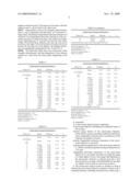
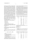
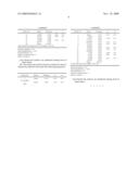
[0008]In the following, three example embodiments of microscope objectives of the "planachromat" class with an optical magnification of -100, a numerical aperture of 1.25 and a visual field factor 20 will be presented. The optical working distance is 0.28 mm. It is the distance between the cover glass and the vertex of the first lens surface in the system. The system data are indicated in Tables 1 to 3.
BRIEF DESCRIPTION OF THE DRAWINGS
[0009]In the respective Figures,
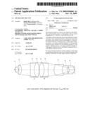
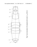
[0010]FIG. 1 shows a lens segment of the objective with the tube f'Tubus=200 mm
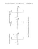
[0011]FIG. 2 shows transverse aberrations with the tube, f'Tubus=200 mm
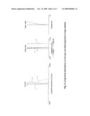
[0012]FIG. 3 shows longitudinal aberrations on the axis and field-dependent image defects.
DETAILED DESCRIPTION
[0013]The objective in the example embodiment 1 in Table 1 is calculated together with a tube lens having a focal length of 180 mm, thus correcting the transverse chromatic aberrations on the edge of the field respectively to -50 μm (C'-e) and 50 μm (F'-e). This correction of the longitudinal chromatic aberration is required for a specific device. The objective in the example embodiment 2 in Table 2 is calculated together with a tube lens having a focal length of 200 mm; in this case, the chromatic aberrations in the objective and in the tube system are each corrected by themselves. The example embodiment 3 in Table 3 is calculated together with a tube lens having a focal length of 164.5 mm; in this case, the transverse chromatic aberrations in the objective and in the tube system are mutually compensated for. By slight changes, the construction of these alternative microscope objectives meet different demands in terms of transverse chromatic aberrations.
[0014]The system data of the three example embodiments are similar. Therefore, only example embodiment 2 will be referred to for the graphic representations. The lens cross-section is shown in FIG. 1. The corresponding profiles of the image defects as a function of the aperture and of the visual field are respectively shown in FIG. 2 and FIG. 3.
[0015]The microscope objectives each consist of 9 lenses with 3 cemented elements, to be precise: (counted starting from the object; see FIG. 1) a lens L1 with positive refractive power, a positive meniscus lens L2, a two-part cemented element G1 with positive refractive power, another two-part cemented element G2 with positive refractive power, a two-part cemented element G3 with negative refractive power and finally a meniscus lens L9 with negative refractive power. The cemented elements G1 and G2 are of identical construction and are built into the system with mirror symmetry (FIG. 1). Further, the lenses L8 and L9 are of identical construction, and they are also built into the objective with mirror symmetry. This results in three pairs of lenses, namely L3 and L6, L4 and L5, L8 and L9, each being of identical construction. This allows an effective reduction in production costs.
[0016]The lens L1 has a plane surface on the object side and a strongly curved surface on the image side, and the center of curvature is located on the object side. The lens L2 is meniscus-shaped and the two centers of curvature are located on the object side. The cemented element G1 is composed of a biconcave lens L3 on the object side and a biconvex lens L4 on the image side. The cemented element G2 consists of a biconvex lens L4 on the object side and a biconcave lens L5 on the image side. The cemented element G3 is composed of two meniscus lenses L7 and L8, and the centers of curvature of all surfaces are located on the image side. The two lenses L7 and L8 have negative refractive power. The centers of curvature of the last meniscus lens L9 are located on the object side.
[0017]Image defects, such as, for example, spherical aberration, coma, astigmatism and distortion, are corrected to a large extent. The primary longitudinal chromatic aberration is corrected. The longitudinal chromatic aberration of the secondary spectrum is within the range of the triple focal depth. Image field flattening is reduced such that the best focus position on the edge of the field deviates from the axial focus position by less than two focal depths. The different aberrations are graphically represented in FIG. 2 and FIG. 3.
[0018]The following Tables show the system data of the example embodiments, and the designation of the surfaces (surface no.) starts from the object plane (beginning on the left).
TABLE-US-00001 TABLE 1 System data of example embodiment 1 Surface No. Radius Thickness ne νe 1 Planar 0.170 1.525 59.2 (Cover glass) 2 Planar 0.290 1.518 41.8 (Oil) 3 Planar 2.770 1.517 60.3 4 -2.0004 0.200 5 -17.4139 2.200 1.758 52.1 6 -5.2970 6.483 7 -99.0800 3.000 1.762 27.3 8 10.3510 4.000 1.667 54.3 9 -17.4720 0.200 10 17.4720 4.000 1.667 54.3 11 -10.3510 3.000 1.762 27.3 12 99.0800 5.329 13 7.6990 6.500 1.489 70.0 14 4.6560 4.000 1.813 25.3 15 2.4300 1.796 16 -2.4300 4.000 1.813 25.3 17 -4.6560 0.622 18 Planar 60.000 +achromatized tube lenses having a focal length of 180 mm Numerical aperture = 1.25 optical magnification = -100.5 visual field factor = 20 Position of entrance pupil -∞ Object on surface 1
TABLE-US-00002 TABLE 2 System data of example embodiment 2 Surface No. Radius Thickness ne νe 1 Planar 0.170 1.525 59.2 (Cover glass) 2 Planar 0.281 1.518 41.8 (Oil) 3 Planar 2.770 1.517 60.3 4 -1.9845 0.200 5 -32.1451 2.200 1.758 52.1 6 -5.8498 7.127 7 -87.1808 3.000 1.762 27.3 8 10.0650 4.000 1.667 54.3 9 -16.4805 0.200 10 16.4805 4.000 1.667 54.3 11 -10.0650 3.000 1.762 27.3 12 87.1808 4.823 13 8.8700 6.500 1.489 70.0 14 4.4577 4.000 1.813 25.3 15 2.4528 1.800 16 -2.4528 4.000 1.813 25.3 17 -4.4577 0.500 18 Planar 100.000 +achromatized tube lenses with a focal length of 200 mm Numerical aperture = 1.25 optical magnification = -100.1 visual field factor = 20 Position of entrance pupil -∞ Object on surface 1
TABLE-US-00003 TABLE 3 System data of example embodiment 3 Surface No. Radius Thickness ne νe 1 Planar 0.170 1.525 59.2 (Cover glass) 2 Planar 0.286 1.518 41.8 (Oil) 3 Planar 2.770 1.517 60.3 4 -1.9995 0.200 5 -15.9107 2.200 1.758 52.1 6 -5.2115 6.535 7 -158.4628 3.000 1.762 27.3 8 10.3216 4.000 1.667 54.3 9 -18.4453 0.200 10 18.4453 4.000 1.667 54.3 11 -10.3216 3.000 1.762 27.3 12 158.4628 5.402 13 7.3766 6.500 1.489 70.0 14 4.7935 4.000 1.813 25.3 15 2.3928 1.800 16 -2.3928 4.000 1.813 25.3 17 -4.7935 0.500 18 Planar 126.500 +a tube lens with a focal length of 164.5 mm Numerical aperture = 1.25 optical magnification = -100.2 visual field factor = 20 Position of entrance pupil -∞ Object on surface 1
Claims:
1. (canceled)
2. A microscope optical system comprising:a microscope objective including anti-symmetric lenses or lens groups;wherein image defects of the microscope objective, selected from a group consisting of spherical aberration, coma, astigmatism, distortion and a combination of the forgoing, are largely corrected;primary longitudinal chromatic aberration of the microscope objective is corrected;nominal optical magnification of the microscope objective is -100 for a numerical aperture (using oil immersion) of 1.25; andlongitudinal chromatic aberrations of the microscope objective for a secondary spectrum are within the range of a triple depth of focus, and image field flattening of the microscope objective is reduced such that a best focus position on an edge of the field differs by less than two depths of focus from an axial focus position.
3. The microscope optical system as claimed in claim 2 wherein the microscope objective comprises 9 lenses with 3 cemented elements, including starting from an object side, a lens which is almost a hemisphere L1 with positive refractive power, a meniscus lens L2 with positive refractive power, a two-part cemented element G1 with positive refractive power, another two-part cemented element G2 with positive refractive power, a two-part cemented element G3 with negative refractive power, and a meniscus lens L9 with negative refractive power, wherein the lens L1 has a plane surface on the object side and a strongly curved surface on an image side thereof and a center of curvature is located on the object side thereof; the lens L2 is meniscus-shaped and the two centers of curvature are located on the object side thereof; the cemented element G1 including a biconcave lens L3 on an object side thereof and a biconvex lens L4 on an image side thereof; the cemented element G2 including a biconvex lens L4 on an object side thereof and a biconcave lens L5 on an image side thereof; the cemented element G3 comprising two meniscus lenses L7 and L8, and the centers of curvature of all surfaces of L7 and L8 are located on an image side thereof and both lenses L7 and L8 have negative refractive power.
4. The microscope optical system as claimed in claim 3, wherein the cemented elements G1 and G2 of the microscope objective are of identical construction and are built into the microscope objective with mirror symmetry, the lenses L8 and L9 are of identical construction and are built into the microscope objective with mirror symmetry, resulting in three pairs of lenses, L3 and L6; L4 and L5; L8 and L9, each being of identical construction.
5. The microscope optical system as claimed in claim 3, wherein the following ratios of the focal lengths apply:1.9<fL1/fObj.<2.44.5<fL2/fObj<5.720- .2<fG1/fObj<25.720.2<fG2/fObj<25.7-14.7<- ;fG3/fObj<-8.2-31.7<fL9/fObj.<-14.2wherein fObj. is the focal length of the objective.
6. The microscope optical system as claimed in claim 4, wherein the lenses L4 and L5 of identical construction satisfy the following conditions:ne>1.66; andνe>54
7. The microscope optical system as claimed in claim 4, wherein the lenses L8 and L9 of identical construction satisfy the following conditions:ne>1.81; andνe<26
8. The microscope optical system as claimed in claim 2, wherein geometry of the lens L1 satisfies the following conditions: d 3 ≧ r 4 ≧ d 1 NA n 1 2 - NA 2 + d 2 NA n 2 2 - NA 2 + d 3 NA n 3 2 - NA 2 ##EQU00001## whereind1 is the thickness of the cover glass;d2 is the optical working distance;d3, r4 respectively are the center thickness and the radius of curvature of the lens L1;NA is the numerical aperture; andne is the refractive index ve for the Abbe number at the spectral line e=546.07 nm.
9. The microscope optical system as claimed in claim 2, further comprising a tube system having a focal length of 180 mm arranged relative to the objective such that rays which come from an object point are parallel to each other between the objective and the tube lens system.
10. The microscope optical system as claimed in claim 2, further comprising a tube system having a focal length of 200 mm, arranged relative to the objective such that rays which come from an object point are parallel to each other between the objective and the tube lens system and wherein chromatic aberrations of the objective and of the tube lens system are corrected separately from each other.
11. The microscope optical system as claimed in claim 2, further comprising a tube lens having a focal length of 164.5 mm; wherein chromatic aberration of the microscope objective is corrected according to the "ICS" (Infinite Colour Correction System) principle and wherein the chromatic aberration of the microscope objective and chromatic aberration tube lens system compensate each other.
12. The microscope optical system as claimed in claim 2, wherein the objective lens meets the following parameters: TABLE-US-00004 Surface No. Radius Thickness ne νe 1 Planar 0.170 1.525 59.2 (Cover glass) 2 Planar 0.290 1.518 41.8 (Oil) 3 Planar 2.770 1.517 60.3 4 -2.0004 0.200 5 -17.4139 2.200 1.758 52.1 6 -5.2970 6.483 7 -99.0800 3.000 1.762 27.3 8 10.3510 4.000 1.667 54.3 9 -17.4720 0.200 10 17.4720 4.000 1.667 54.3 11 -10.3510 3.000 1.762 27.3 12 99.0800 5.329 13 7.6990 6.500 1.489 70.0 14 4.6560 4.000 1.813 25.3 15 2.4300 1.796 16 -2.4300 4.000 1.813 25.3 17 -4.6560 0.622 18 Planar 60.000 +achromatized tube lenses having a focal length of 180 mm Numerical aperture = 1.25 optical magnification = -100.5 visual field factor = 20 Position of entrance pupil -.infin. Object on surface 1
and wherein the surfaces are numbered starting from an object plane.
13. The microscope optical system as claimed in claim 2, wherein the objective lens meets the following parameters: TABLE-US-00005 Surface No. Radius Thickness ne νe 1 Planar 0.170 1.525 59.2 (Cover glass) 2 Planar 0.281 1.518 41.8 (Oil) 3 Planar 2.770 1.517 60.3 4 -1.9845 0.200 5 -32.1451 2.200 1.758 52.1 6 -5.8498 7.127 7 -87.1808 3.000 1.762 27.3 8 10.0650 4.000 1.667 54.3 9 -16.4805 0.200 10 16.4805 4.000 1.667 54.3 11 -10.0650 3.000 1.762 27.3 12 87.1808 4.823 13 8.8700 6.500 1.489 70.0 14 4.4577 4.000 1.813 25.3 15 2.4528 1.800 16 -2.4528 4.000 1.813 25.3 17 -4.4577 0.500 18 Planar 100.000 +achromatized tube lenses with a focal length of 200 mm Numerical aperture = 1.25 optical magnification = -100.1 visual field factor = 20 Position of entrance pupil -.infin. Object on surface 1
and wherein the surfaces are numbered starting from an object plane.
14. The microscope optical system as claimed in claim 2, wherein the objective lens meets the following parameters: TABLE-US-00006 Surface No. Radius Thickness ne νe 1 Planar 0.170 1.525 59.2 (Cover glass) 2 Planar 0.286 1.518 41.8 (Oil) 3 Planar 2.770 1.517 60.3 4 -1.9995 0.200 5 -15.9107 2.200 1.758 52.1 6 -5.2115 6.535 7 -158.4628 3.000 1.762 27.3 8 10.3216 4.000 1.667 54.3 9 -18.4453 0.200 10 18.4453 4.000 1.667 54.3 11 -10.3216 3.000 1.762 27.3 12 158.4628 5.402 13 7.3766 6.500 1.489 70.0 14 4.7935 4.000 1.813 25.3 15 2.3928 1.800 16 -2.3928 4.000 1.813 25.3 17 -4.7935 0.500 18 Planar 126.500 +a tube lens with a focal length of 164.5 mm Numerical aperture = 1.25 optical magnification = -100.2 visual field factor = 20 Position of entrance pupil -.infin. Object on surface 1
and wherein the surfaces are numbered starting from an object plane.
Description:
PRIORITY CLAIM
[0001]The present application is a National Phase entry of PCT Application No. PCT/EP2007/003673, filed Apr. 26, 2007, which claims priority from German Application Number 102006021520.6, filed May 5, 2006, the disclosures of which are hereby incorporated by reference herein in their entirety.
FIELD OF THE INVENTION
[0002]For examination of biological objects and of tissue cultures use is made of microscope objectives having a large numerical aperture so as to resolve the fine structure.
BACKGROUND
[0003]The microscope objectives with a numerical aperture of greater than 1.2 and using immersion oil usually also have higher production costs. This is partially due to the fact that the front part of the corresponding objective consists of a two-part cemented element, i.e. one which comprises a plano-convex lens and a meniscus lens. Due to the special method of manufacture, the production of such a cemented element is complex and expensive. Objectives with a front part consisting of only one hemisphere lens may reach an aperture of up to 1.3 and have lower production costs.
SUMMARY OF THE INVENTION
[0004]In view of the disadvantages of the prior art, it is an object of the invention to improve a microscope objective such that, by improvement of the image contrast, a further reduction in production costs is achieved.
[0005]Alternatively, the solution according to the invention relates to three microscope objective variants of the "planachromat" class having an optical magnification of -100 and a visual field factor of 20. A planachromat is defined by the coincidence in focal position of the spectral lines C' and F'. The additional term "plan" means that the image field is suitably flattened. The object-side numerical aperture is 1.25.
[0006]The microscope objective consists of 9 lenses comprising 3 cemented elements. The image contrast is influenced at the first line by the image defects. In the present microscope objectives, image defects such as spherical aberration, coma, astigmatism and distortion, are corrected to a further extent. The primary longitudinal chromatic aberration (image of the focus positions between the spectral lines C' and F') has been corrected. The longitudinal chromatic aberration of the secondary spectrum (deviation of the focus positions between the spectral lines C'-e and F'-e) is within the range of the triple depth of focus. The range of the focal depth is defined by λ/NA2 with NA as the numerical aperture. This range is referred to as a Rayleigh unit. Image field flattening is reduced such that the best focus position at the field edge deviates by less than two focal depths from the axial focus position.
[0007]The use of repetitive components allows a further reduction in production costs. Such a microscope objective offers customers flexibility and the cost benefit.
[0008]In the following, three example embodiments of microscope objectives of the "planachromat" class with an optical magnification of -100, a numerical aperture of 1.25 and a visual field factor 20 will be presented. The optical working distance is 0.28 mm. It is the distance between the cover glass and the vertex of the first lens surface in the system. The system data are indicated in Tables 1 to 3.
BRIEF DESCRIPTION OF THE DRAWINGS
[0009]In the respective Figures,
[0010]FIG. 1 shows a lens segment of the objective with the tube f'Tubus=200 mm
[0011]FIG. 2 shows transverse aberrations with the tube, f'Tubus=200 mm
[0012]FIG. 3 shows longitudinal aberrations on the axis and field-dependent image defects.
DETAILED DESCRIPTION
[0013]The objective in the example embodiment 1 in Table 1 is calculated together with a tube lens having a focal length of 180 mm, thus correcting the transverse chromatic aberrations on the edge of the field respectively to -50 μm (C'-e) and 50 μm (F'-e). This correction of the longitudinal chromatic aberration is required for a specific device. The objective in the example embodiment 2 in Table 2 is calculated together with a tube lens having a focal length of 200 mm; in this case, the chromatic aberrations in the objective and in the tube system are each corrected by themselves. The example embodiment 3 in Table 3 is calculated together with a tube lens having a focal length of 164.5 mm; in this case, the transverse chromatic aberrations in the objective and in the tube system are mutually compensated for. By slight changes, the construction of these alternative microscope objectives meet different demands in terms of transverse chromatic aberrations.
[0014]The system data of the three example embodiments are similar. Therefore, only example embodiment 2 will be referred to for the graphic representations. The lens cross-section is shown in FIG. 1. The corresponding profiles of the image defects as a function of the aperture and of the visual field are respectively shown in FIG. 2 and FIG. 3.
[0015]The microscope objectives each consist of 9 lenses with 3 cemented elements, to be precise: (counted starting from the object; see FIG. 1) a lens L1 with positive refractive power, a positive meniscus lens L2, a two-part cemented element G1 with positive refractive power, another two-part cemented element G2 with positive refractive power, a two-part cemented element G3 with negative refractive power and finally a meniscus lens L9 with negative refractive power. The cemented elements G1 and G2 are of identical construction and are built into the system with mirror symmetry (FIG. 1). Further, the lenses L8 and L9 are of identical construction, and they are also built into the objective with mirror symmetry. This results in three pairs of lenses, namely L3 and L6, L4 and L5, L8 and L9, each being of identical construction. This allows an effective reduction in production costs.
[0016]The lens L1 has a plane surface on the object side and a strongly curved surface on the image side, and the center of curvature is located on the object side. The lens L2 is meniscus-shaped and the two centers of curvature are located on the object side. The cemented element G1 is composed of a biconcave lens L3 on the object side and a biconvex lens L4 on the image side. The cemented element G2 consists of a biconvex lens L4 on the object side and a biconcave lens L5 on the image side. The cemented element G3 is composed of two meniscus lenses L7 and L8, and the centers of curvature of all surfaces are located on the image side. The two lenses L7 and L8 have negative refractive power. The centers of curvature of the last meniscus lens L9 are located on the object side.
[0017]Image defects, such as, for example, spherical aberration, coma, astigmatism and distortion, are corrected to a large extent. The primary longitudinal chromatic aberration is corrected. The longitudinal chromatic aberration of the secondary spectrum is within the range of the triple focal depth. Image field flattening is reduced such that the best focus position on the edge of the field deviates from the axial focus position by less than two focal depths. The different aberrations are graphically represented in FIG. 2 and FIG. 3.
[0018]The following Tables show the system data of the example embodiments, and the designation of the surfaces (surface no.) starts from the object plane (beginning on the left).
TABLE-US-00001 TABLE 1 System data of example embodiment 1 Surface No. Radius Thickness ne νe 1 Planar 0.170 1.525 59.2 (Cover glass) 2 Planar 0.290 1.518 41.8 (Oil) 3 Planar 2.770 1.517 60.3 4 -2.0004 0.200 5 -17.4139 2.200 1.758 52.1 6 -5.2970 6.483 7 -99.0800 3.000 1.762 27.3 8 10.3510 4.000 1.667 54.3 9 -17.4720 0.200 10 17.4720 4.000 1.667 54.3 11 -10.3510 3.000 1.762 27.3 12 99.0800 5.329 13 7.6990 6.500 1.489 70.0 14 4.6560 4.000 1.813 25.3 15 2.4300 1.796 16 -2.4300 4.000 1.813 25.3 17 -4.6560 0.622 18 Planar 60.000 +achromatized tube lenses having a focal length of 180 mm Numerical aperture = 1.25 optical magnification = -100.5 visual field factor = 20 Position of entrance pupil -∞ Object on surface 1
TABLE-US-00002 TABLE 2 System data of example embodiment 2 Surface No. Radius Thickness ne νe 1 Planar 0.170 1.525 59.2 (Cover glass) 2 Planar 0.281 1.518 41.8 (Oil) 3 Planar 2.770 1.517 60.3 4 -1.9845 0.200 5 -32.1451 2.200 1.758 52.1 6 -5.8498 7.127 7 -87.1808 3.000 1.762 27.3 8 10.0650 4.000 1.667 54.3 9 -16.4805 0.200 10 16.4805 4.000 1.667 54.3 11 -10.0650 3.000 1.762 27.3 12 87.1808 4.823 13 8.8700 6.500 1.489 70.0 14 4.4577 4.000 1.813 25.3 15 2.4528 1.800 16 -2.4528 4.000 1.813 25.3 17 -4.4577 0.500 18 Planar 100.000 +achromatized tube lenses with a focal length of 200 mm Numerical aperture = 1.25 optical magnification = -100.1 visual field factor = 20 Position of entrance pupil -∞ Object on surface 1
TABLE-US-00003 TABLE 3 System data of example embodiment 3 Surface No. Radius Thickness ne νe 1 Planar 0.170 1.525 59.2 (Cover glass) 2 Planar 0.286 1.518 41.8 (Oil) 3 Planar 2.770 1.517 60.3 4 -1.9995 0.200 5 -15.9107 2.200 1.758 52.1 6 -5.2115 6.535 7 -158.4628 3.000 1.762 27.3 8 10.3216 4.000 1.667 54.3 9 -18.4453 0.200 10 18.4453 4.000 1.667 54.3 11 -10.3216 3.000 1.762 27.3 12 158.4628 5.402 13 7.3766 6.500 1.489 70.0 14 4.7935 4.000 1.813 25.3 15 2.3928 1.800 16 -2.3928 4.000 1.813 25.3 17 -4.7935 0.500 18 Planar 126.500 +a tube lens with a focal length of 164.5 mm Numerical aperture = 1.25 optical magnification = -100.2 visual field factor = 20 Position of entrance pupil -∞ Object on surface 1
User Contributions:
Comment about this patent or add new information about this topic:
Images included with this patent application:
 |  |
 |  |
 |  |
 |
| Similar patent applications: | |
| Date | Title |
|---|---|
| 2011-05-26 | Method and apparatus for detecting microscopic objects |
| 2012-09-27 | Microscope optical system |
| 2010-05-06 | Microscope slide coverslip and uses thereof |
| 2011-01-06 | Microscope system and method for controlling it |
| 2011-06-30 | Microscope control unit |
| New patent applications in this class: | |
| Date | Title |
|---|---|
| 2016-07-14 | Optical system and optical instrument, image pickup apparatus, and image pickup system using the same |
| 2016-04-28 | Objective for microscope |
| 2015-05-28 | Immersion microscope objective and microscope using the same |
| 2015-04-23 | Immersion microscope objective and microscope using the same |
| 2015-04-23 | Immersion microscope objective and microscope using the same |
| New patent applications from these inventors: | |
| Date | Title |
|---|---|
| 2013-10-17 | Immersion objective and light microscope |
| 2013-01-31 | Attachment of optical microscope components |
| 2012-10-04 | Arrangement for equalizing binocular visual fields |
| 2009-09-10 | Calibration device and laser scanning microscope with such a calibration device |
| Top Inventors for class "Optical: systems and elements" | |
| Rank | Inventor's name |
|---|---|
| 1 | Tsung Han Tsai |
| 2 | Hsin Hsuan Huang |
| 3 | Michio Cho |
| 4 | Niall R. Lynam |
| 5 | Tsung-Han Tsai |