Patent application title: MOTOR VEHICLE WITH A REAR END MOUNTED BATTERY BOX
Inventors:
Klas Rydberg (Vastra Frolunda, SE)
Thomas Storsjo (Halleviksstrand, SE)
Fredrik Bengtsson (Goteborg, SE)
Jan-Olof Bodin (Alingsas, SE)
Sylvie Chapon (Goteborg, SE)
Martin Olofsson (Goteborg, SE)
Assignees:
VOLVO LASTVAGNAR AB
IPC8 Class: AB60R1604FI
USPC Class:
180 685
Class name: Motor vehicles power battery mountings and holders
Publication date: 2009-01-15
Patent application number: 20090014224
a frame chassis including two longitudinal beams
and at least first and second cross members between the two longitudinal
beams, and a battery box arranged at the rear end of the vehicle between
the beams with vibration damping mounts, wherein the mounts of the
battery box comprise a front mount connecting the front side of the
battery box to the first adjacent cross member and a rear mount
connecting the rear side opposing the front side of the battery box to
the second adjacent cross member. By suspending the battery box from the
cross members of the chassis frame, the mounting brackets do not collide
with other components that must be accommodated in or mounted on the
longitudinal chassis beams. Moreover, the battery support system
according to the invention provides an advantage in terms of space.Claims:
1. A motor vehicle comprisinga frame chassis including two longitudinal
beams and at least a first and second cross members between the two
longitudinal beams, anda battery box arranged at a rear end of the
vehicle between the beams with vibration damping mount, wherein the
mounting means of the battery box comprises a front mount connecting a
front side of the battery box to the first cross member and a rear mount
connecting a rear side of the battery box opposing the front side of the
battery box to the second cross member.
2. A vehicle according to claim 1, wherein the front and rear mounts comprise rubber suspension brackets providing an elastomeric connection between the battery box and the cross members.
3. A vehicle according to claim 1, wherein the battery box is mounted with three mounting brackets, where the front mount comprises at least one bracket and the rear mount comprises at least two brackets.
4. A vehicle according to claim 1, wherein the battery box is mounted with three mounting brackets, where the front mount comprises at least two brackets and the rear mount comprises at least one bracket.
5. A vehicle according to claim 3, wherein the front and rear mounts comprise four brackets for mounting the battery box.
6. A vehicle according to claim 1, wherein the front and rear mounts provide a symmetrical mounting of the battery box along a longitudinal axis of the vehicle.Description:
BACKGROUND AND SUMMARY
[0001]The present invention relates to a motor vehicle comprising a frame chassis including two longitudinal beams and at least a first and second cross members between said two longitudinal beams, and a battery box arranged at the rear end of the vehicle between said beams with mounting means.
[0002]A battery box support assembly of such kind is known from EP 1334881 A2.
[0003]In particular in some semi-tractor variants, the battery box is positioned in the rear end of the truck, i.e. the end of the frame, in order to ensure a good weight distribution in the truck and because the space in the centre of the vehicle is limited. This rear end battery position is also advantageous as the batteries are well protected in case of a collision as they are positioned inside the chassis frame at the rear of the truck. However, this rear end battery position also displays some drawbacks. The movement of the frame is greater in the rear of the truck than in the centre of the truck. This applies both to vibrations caused by an uneven ground and to sideways movements caused by turning. Vibrations caused by an uneven ground will introduce longitudinal and horizontal movements.
[0004]The battery box known from EP 1334881 A2 is resiliently mounted to the longitudinal beams of the vehicle. Although the batteries may be protected from these longitudinal and horizontal movements by the known system, the battery box support system does not absorb the sideways movements due to vehicle turning. One reason is that the resilient mounting means are adapted for longitudinal and horizontal movements. Another reason is that the truck frame is less stiff when it comes to side forces. Since the batteries are heavy. The frame will thus flex somewhat, particularly in the rear end of the truck.
[0005]The movements caused by turning will be much greater than the movements caused by vibrations since a small turning action with the steering wheel will cause a large movement at the rear of the truck. To extend the life of the batteries, it is advantageous to limit the movement of the batteries as much as possible.
[0006]Moreover, the battery support system of EP 1 334 881 may be difficult to arrange due to other parts that must be mounted to the longitudinal chassis frame or accommodated inside the cavity of the chassis frame beams.
[0007]On this background, it is desirable to provide a vehicle with a rear end mounted battery box without the above-identified drawbacks.
[0008]According to an aspect of the present invention, a motor vehicle of the initially mentioned kind is provided, wherein the mounting means of the battery box comprises front mounting means connecting the front side of the battery box to the first adjacent cross member and rear mounting means connecting the rear side opposing said front side of the battery box to the second adjacent cross member.
[0009]By mounting and suspending the battery box from the cross members of the chassis frame, the mounting brackets do not collide with other components that must be accommodated in or mounted on the longitudinal chassis beams. Moreover, the battery support system according to an aspect of the invention provides an advantage in terms of space. A low battery position may be advantageous with respect to weight distribution in the vehicle and contribute to a low centre of gravity of the vehicle. A low battery installation is possible by an aspect of the invention since the mounting brackets can be placed on the cross members relatively unrestricted, or the cross members may be specially designed to provide for a low position of the battery box. By an aspect of the invention it is possible to tailor the position of the cross members and the vertical position of the battery box.
[0010]A further advantage is that the cross members are stiffer for side forces caused by sideway movements, e.g. caused by turning. By an aspect of the invention, it is realised that the mounting brackets are typically less dampening with respect to compression and stretching than to bending. Consequently, by an aspect of the invention a higher sideways stiffness is achieved.
[0011]Advantageously, the mounting means comprises rubber suspension brackets providing an elastomeric connection between the battery box and the cross members of the vehicle frame. However, it is realised that other types of brackets or vibration or movement absorbing mounting means may be used for connecting the battery box to the vehicle frame.
[0012]The front and rear mounting means may be different in respect to size and/or resilient characteristics. This may be advantageous since the movements at the front and the rear of the battery box differs in amplitude. When the front or the rear mounting means is a single mounting bracket, this may comprise a hinge.
[0013]The mounting means may preferably comprise four brackets for mounting the battery box. However, it is realised by an aspect of the invention that the battery box may be mounted with three mounting brackets, where either the front mounting means comprise at least one bracket and the rear mounting means comprises at least two brackets or where the front mounting means comprise at least two brackets and the rear mounting means comprises at least one bracket. A three point mounting of the battery box in the vehicle frame may be advantageous e.g. if the space is limited due to other components that must be fitted to the frame, if the weight distribution in the battery box is uneven, or if a special vibration dampening characteristics is required.
[0014]Preferably, the mounting means provide a symmetrical mounting of the battery box along the longitudinal axis of the vehicle. However, an asymmetric mounting is made possible by e.g. a three point mounting.
DESCRIPTION OF THE DRAWINGS
[0015]In the following the invention is described in more detail with reference to the accompanying drawings, in which:
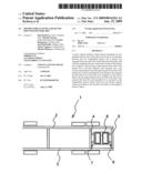
[0016]FIG. 1 is a schematic side view of a vehicle with a rear end mounted battery;
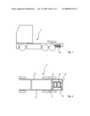
[0017]FIG. 2 is a schematic top view of a chassis of a vehicle according to an aspect of the invention;
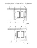
[0018]FIG. 3 is a schematic detailed view of the rear end of a vehicle chassis according to a first embodiment of the invention, and
[0019]FIG. 4 is a schematic detailed view of the rear end of a vehicle chassis according to a second embodiment of the invention.
DETAILED DESCRIPTION
[0020]FIG. 1 shows a truck with a battery box 6 mounted in the rear end of the vehicle frame chassis 1. This battery position is advantageous in many trucks or tractors, as this leaves more space between the wheels for fuel tanks and other fluid containers that may be installed on the truck. The weight distribution is also advantageous.
[0021]As shown in FIG. 2, the vehicle frame chassis 1 comprise two longitudinal chassis beams 2, 3 with a number of cross members 4, 5. The battery box 6 is mounted between the two longitudinal chassis beams 2, 3 and between the two rearmost cross members 4, 5. For a longer truck, the battery box may also be mounted between other cross members than the rearmost ones. The battery box is mounted to the cross members 4, 5 by vibration absorbing mounting brackets 7, 8 preferably including mounting rubber bushings. Typically, the cross members 4, 5 are positioned somewhat lower than the longitudinal beams 2, 3 in the frame chassis 1. By mounting the battery box 6 to the cross members 4, 5 a low position of the batteries may be obtained and thereby an advantageous weight distribution in the vehicle.
[0022]The battery box 6 comprises a carrier frame which accommodates one or more batteries. The box 6 may be mounted with one or more mounting brackets 7 at the front side of the battery box 6 and one or more brackets 8 at the rear of the battery box 6. Two examples of the battery box 6 mounting are shown in FIGS. 3 and 4, where the battery box 6 is mounted over four and three mounting brackets 7, 8, respectively. The number of mounting brackets 7, 8 and their positions may be chosen according to the specific requirements allowing for a high degree of flexibility in the battery box mounting design, whereby it is possible to tailor the battery installation on the truck to the actual requirements. As indicated in FIG. 4, the mounting brackets 7, 8 may be individually designed and dimensioned to achieve the required vibration damping mounting installation of the battery box 6.
[0023]The mounting brackets 7, 8 may de designed to suspend the battery box 6 from the cross members 4, 5 of the vehicle frame 1. The mounting brackets 7, 8 preferably include rubber bushings or similar elastomeric materials whereby vibrations in the chassis frame and movements of the vehicle may be absorbed rather than transferred to the batteries in the battery box 6. The rubber suspension mounting contributes to increasing the lifetime of the batteries.
[0024]It is understood that the terms front and rear used throughout this description and in the accompanying claims refer to the main driving direction of the vehicle.
[0025]The invention is described above with reference to some preferred embodiments. However, it is further understood that variations of the invention may be performed without departing from the scope of the invention as defined in the claims. For instance, two front mounting brackets 7 and one rear mounting bracket 8 may be chosen in accordance with the actual circumstances.
Claims:
1. A motor vehicle comprisinga frame chassis including two longitudinal
beams and at least a first and second cross members between the two
longitudinal beams, anda battery box arranged at a rear end of the
vehicle between the beams with vibration damping mount, wherein the
mounting means of the battery box comprises a front mount connecting a
front side of the battery box to the first cross member and a rear mount
connecting a rear side of the battery box opposing the front side of the
battery box to the second cross member.
2. A vehicle according to claim 1, wherein the front and rear mounts comprise rubber suspension brackets providing an elastomeric connection between the battery box and the cross members.
3. A vehicle according to claim 1, wherein the battery box is mounted with three mounting brackets, where the front mount comprises at least one bracket and the rear mount comprises at least two brackets.
4. A vehicle according to claim 1, wherein the battery box is mounted with three mounting brackets, where the front mount comprises at least two brackets and the rear mount comprises at least one bracket.
5. A vehicle according to claim 3, wherein the front and rear mounts comprise four brackets for mounting the battery box.
6. A vehicle according to claim 1, wherein the front and rear mounts provide a symmetrical mounting of the battery box along a longitudinal axis of the vehicle.
Description:
BACKGROUND AND SUMMARY
[0001]The present invention relates to a motor vehicle comprising a frame chassis including two longitudinal beams and at least a first and second cross members between said two longitudinal beams, and a battery box arranged at the rear end of the vehicle between said beams with mounting means.
[0002]A battery box support assembly of such kind is known from EP 1334881 A2.
[0003]In particular in some semi-tractor variants, the battery box is positioned in the rear end of the truck, i.e. the end of the frame, in order to ensure a good weight distribution in the truck and because the space in the centre of the vehicle is limited. This rear end battery position is also advantageous as the batteries are well protected in case of a collision as they are positioned inside the chassis frame at the rear of the truck. However, this rear end battery position also displays some drawbacks. The movement of the frame is greater in the rear of the truck than in the centre of the truck. This applies both to vibrations caused by an uneven ground and to sideways movements caused by turning. Vibrations caused by an uneven ground will introduce longitudinal and horizontal movements.
[0004]The battery box known from EP 1334881 A2 is resiliently mounted to the longitudinal beams of the vehicle. Although the batteries may be protected from these longitudinal and horizontal movements by the known system, the battery box support system does not absorb the sideways movements due to vehicle turning. One reason is that the resilient mounting means are adapted for longitudinal and horizontal movements. Another reason is that the truck frame is less stiff when it comes to side forces. Since the batteries are heavy. The frame will thus flex somewhat, particularly in the rear end of the truck.
[0005]The movements caused by turning will be much greater than the movements caused by vibrations since a small turning action with the steering wheel will cause a large movement at the rear of the truck. To extend the life of the batteries, it is advantageous to limit the movement of the batteries as much as possible.
[0006]Moreover, the battery support system of EP 1 334 881 may be difficult to arrange due to other parts that must be mounted to the longitudinal chassis frame or accommodated inside the cavity of the chassis frame beams.
[0007]On this background, it is desirable to provide a vehicle with a rear end mounted battery box without the above-identified drawbacks.
[0008]According to an aspect of the present invention, a motor vehicle of the initially mentioned kind is provided, wherein the mounting means of the battery box comprises front mounting means connecting the front side of the battery box to the first adjacent cross member and rear mounting means connecting the rear side opposing said front side of the battery box to the second adjacent cross member.
[0009]By mounting and suspending the battery box from the cross members of the chassis frame, the mounting brackets do not collide with other components that must be accommodated in or mounted on the longitudinal chassis beams. Moreover, the battery support system according to an aspect of the invention provides an advantage in terms of space. A low battery position may be advantageous with respect to weight distribution in the vehicle and contribute to a low centre of gravity of the vehicle. A low battery installation is possible by an aspect of the invention since the mounting brackets can be placed on the cross members relatively unrestricted, or the cross members may be specially designed to provide for a low position of the battery box. By an aspect of the invention it is possible to tailor the position of the cross members and the vertical position of the battery box.
[0010]A further advantage is that the cross members are stiffer for side forces caused by sideway movements, e.g. caused by turning. By an aspect of the invention, it is realised that the mounting brackets are typically less dampening with respect to compression and stretching than to bending. Consequently, by an aspect of the invention a higher sideways stiffness is achieved.
[0011]Advantageously, the mounting means comprises rubber suspension brackets providing an elastomeric connection between the battery box and the cross members of the vehicle frame. However, it is realised that other types of brackets or vibration or movement absorbing mounting means may be used for connecting the battery box to the vehicle frame.
[0012]The front and rear mounting means may be different in respect to size and/or resilient characteristics. This may be advantageous since the movements at the front and the rear of the battery box differs in amplitude. When the front or the rear mounting means is a single mounting bracket, this may comprise a hinge.
[0013]The mounting means may preferably comprise four brackets for mounting the battery box. However, it is realised by an aspect of the invention that the battery box may be mounted with three mounting brackets, where either the front mounting means comprise at least one bracket and the rear mounting means comprises at least two brackets or where the front mounting means comprise at least two brackets and the rear mounting means comprises at least one bracket. A three point mounting of the battery box in the vehicle frame may be advantageous e.g. if the space is limited due to other components that must be fitted to the frame, if the weight distribution in the battery box is uneven, or if a special vibration dampening characteristics is required.
[0014]Preferably, the mounting means provide a symmetrical mounting of the battery box along the longitudinal axis of the vehicle. However, an asymmetric mounting is made possible by e.g. a three point mounting.
DESCRIPTION OF THE DRAWINGS
[0015]In the following the invention is described in more detail with reference to the accompanying drawings, in which:
[0016]FIG. 1 is a schematic side view of a vehicle with a rear end mounted battery;
[0017]FIG. 2 is a schematic top view of a chassis of a vehicle according to an aspect of the invention;
[0018]FIG. 3 is a schematic detailed view of the rear end of a vehicle chassis according to a first embodiment of the invention, and
[0019]FIG. 4 is a schematic detailed view of the rear end of a vehicle chassis according to a second embodiment of the invention.
DETAILED DESCRIPTION
[0020]FIG. 1 shows a truck with a battery box 6 mounted in the rear end of the vehicle frame chassis 1. This battery position is advantageous in many trucks or tractors, as this leaves more space between the wheels for fuel tanks and other fluid containers that may be installed on the truck. The weight distribution is also advantageous.
[0021]As shown in FIG. 2, the vehicle frame chassis 1 comprise two longitudinal chassis beams 2, 3 with a number of cross members 4, 5. The battery box 6 is mounted between the two longitudinal chassis beams 2, 3 and between the two rearmost cross members 4, 5. For a longer truck, the battery box may also be mounted between other cross members than the rearmost ones. The battery box is mounted to the cross members 4, 5 by vibration absorbing mounting brackets 7, 8 preferably including mounting rubber bushings. Typically, the cross members 4, 5 are positioned somewhat lower than the longitudinal beams 2, 3 in the frame chassis 1. By mounting the battery box 6 to the cross members 4, 5 a low position of the batteries may be obtained and thereby an advantageous weight distribution in the vehicle.
[0022]The battery box 6 comprises a carrier frame which accommodates one or more batteries. The box 6 may be mounted with one or more mounting brackets 7 at the front side of the battery box 6 and one or more brackets 8 at the rear of the battery box 6. Two examples of the battery box 6 mounting are shown in FIGS. 3 and 4, where the battery box 6 is mounted over four and three mounting brackets 7, 8, respectively. The number of mounting brackets 7, 8 and their positions may be chosen according to the specific requirements allowing for a high degree of flexibility in the battery box mounting design, whereby it is possible to tailor the battery installation on the truck to the actual requirements. As indicated in FIG. 4, the mounting brackets 7, 8 may be individually designed and dimensioned to achieve the required vibration damping mounting installation of the battery box 6.
[0023]The mounting brackets 7, 8 may de designed to suspend the battery box 6 from the cross members 4, 5 of the vehicle frame 1. The mounting brackets 7, 8 preferably include rubber bushings or similar elastomeric materials whereby vibrations in the chassis frame and movements of the vehicle may be absorbed rather than transferred to the batteries in the battery box 6. The rubber suspension mounting contributes to increasing the lifetime of the batteries.
[0024]It is understood that the terms front and rear used throughout this description and in the accompanying claims refer to the main driving direction of the vehicle.
[0025]The invention is described above with reference to some preferred embodiments. However, it is further understood that variations of the invention may be performed without departing from the scope of the invention as defined in the claims. For instance, two front mounting brackets 7 and one rear mounting bracket 8 may be chosen in accordance with the actual circumstances.
User Contributions:
Comment about this patent or add new information about this topic:
| People who visited this patent also read: | |
| Patent application number | Title |
|---|---|
| 20180336068 | Application Load Adaptive Multi-stage Parallel Data Processing Architecture |
| 20180336067 | METHOD AND APPARATUS FOR DATA PROCESSING BASED ON MULTICORE |
| 20180336066 | SYSTEM AND METHOD TO CONTROL HEAT DISSIPATION THROUGH SERVICE LEVEL ANALYSIS |
| 20180336065 | DATA PROCESSING SYSTEMS |
| 20180336064 | METHOD FOR DETERMINING EARLIEST DEADLINE FIRST SCHEDULABILITY OF NON-PREEMPTIVE UNI-PROCESSOR SYSTEM |
Images included with this patent application:
 |  |
 |
| New patent applications in this class: | |
| Date | Title |
|---|---|
| 2017-08-17 | Fuel cell vehicle |
| 2016-12-29 | Battery frame and vehicle battery mounting structure |
| 2016-09-01 | Bicycle battery holder, bicycle battery, and retaining member for bicycle battery |
| 2016-09-01 | Battery protection structure |
| 2016-07-14 | Battery changing device for an electrically drivable vehicle |
| New patent applications from these inventors: | |
| Date | Title |
|---|---|
| 2008-11-20 | Device for use with liquid container for a vehicle and method for mounting said liquid container |
| Top Inventors for class "Motor vehicles" | |
| Rank | Inventor's name |
|---|---|
| 1 | Yoshimoto Matsuda |
| 2 | Toru Takenaka |
| 3 | Daniel E. Williams |
| 4 | Shinji Ichikawa |
| 5 | Hiroshi Gomi |