Patent application title: Window Panel With Fabric-Displaying Securement
Inventors:
IPC8 Class: AA47H1314FI
USPC Class:
1 1
Class name:
Publication date: 2018-08-16
Patent application number: 20180228312
Abstract:
A securement means to secure and display a fabric in a form of a panel to
be used as a window treatment, shower curtain, etc. is provided. The
securement means can include an arrangement of securements that allow for
suspension of the panel from a support unit. The arrangement can include
sets of securement with predefined spacings that may generate a natural
tendency to form a plurality of pleats in an even and consistent manner.
The securement means can further include a lead-in securement. The
lead-in securement can be positioned to have a predefined spacing between
it and a lateral side of the panel that the lead-in securement is most
proximal to. Any of the spacings can further allow the panel to be
suspended from the support unit without the panel interfering with a
window treatment positioned behind the panel.Claims:
1. A securement means, comprising a plurality of sets of securements,
each set of securements located on and/or into a portion of a fabric to
form a linear array of securements across the portion of the fabric; and,
wherein each set of securements comprises at least two securements having
a spacing d-i between each securement within the set of securements;
wherein each set of securements has a spacing j-i between each set of
securements; and, wherein each d-i is less than each j-i.
2. The securement means recited in claim 1, wherein the fabric is a panel configured to be suspended from a support unit via the securement means.
3. The securement means recited in claim 1, wherein the fabric is a fabric-extension attached to a panel, the panel configured to be suspended from a support unit via the securement means.
4. The securement means recited in claim 1, wherein the plurality of securements is located at or near a top portion of the fabric.
5. The securement means recited in claim 1, wherein the plurality of securements forms a plurality of linear arrays of securements.
6. The securement means recited in claim 1, wherein any one securement is at least one of formed onto the fabric, formed into the fabric, attached to the fabric, and attachable to the fabric.
7. The securement means recited in claim 1, wherein any one securement is at least one of an aperture and a strap.
8. The securement means recited in claim 1, wherein: the fabric is a first fabric and is configured to be suspended from a first support unit via the securement means, the first support unit extending from a framed-in unit having an opening, the first support unit configured to suspend the first fabric so that a second fabric is suspended by a second support unit between the first fabric and the framed-in unit; the first fabric further comprises a first lateral side and a second lateral side; the securement most proximal to the first lateral side is a first lead-in securement and a spacing between the first lead-in securement and a distal edge of the first lateral side is k-i; the securement most proximal to the second lateral side is a second lead-in securement and a spacing between the second lead-in securement and a distal edge of the second lateral side is k-i; and, each k-i is set at a length so that the distal edges of the first and second lateral sides of the first fabric do not make contact with the second fabric.
9. A securement means, comprising a plurality of sets of securements, each set of securements located on and/or into a portion of a first fabric to form a linear array of securements across the portion of the first fabric, the first fabric comprising a first lateral side and a second lateral side; a first lead-in securement located at or near the first lateral side; and, a second lead-in securement located at or near the second lateral side; wherein each set of securements comprises at least two securements having a spacing d-i between each securement within the set of securements; wherein each set of securements has a spacing j-i between each set of securements; wherein each d-i is less than each j-i; wherein a spacing between the first lead-in securement and a distal edge of the first lateral side is k-i, and a spacing between the second lead-in securement and a distal edge of the second lateral side is k-i; wherein the first fabric and is configured to be suspended from a first support unit via the securement means, the first support unit extending from a framed-in unit having an opening, the first support unit configured to suspend the first fabric so that a second fabric is suspended by a second support unit between the first fabric and the framed-in unit; and, wherein each k-i is set at a length so that the distal edges of the first and second lateral sides of the first fabric do not make contact with the second fabric.
10. The securement means recited in claim 9, wherein the first fabric is a panel configured to be suspended from the first support unit via the securement means.
11. The securement means recited in claim 9, wherein the first fabric is a fabric-extension attached to a panel, the panel configured to be suspended from the first support unit via the securement means.
12. The securement means recited in claim 9, wherein the plurality of securements is located at or near a top portion of the fabric.
13. The securement means recited in claim 9, wherein the plurality of securements forms a plurality of linear arrays of securements.
14. The securement means recited in claim 9, wherein any one securement is at least one of formed onto the fabric, formed into the fabric, attached to the fabric, and attachable to the fabric.
15. The securement means recited in claim 9, wherein any one securement is at least one of an aperture and a strap.
16. A panel configured for use as a window treatment, comprising a fabric comprising a top, a first lateral side, a second lateral side, and a bottom; a plurality of securements, each securement located on and/or into a portion of the panel to form a linear array of securements across the portion of the panel; and, at least one set of securements formed within the linear array of securements, each set of securements comprising at least two securements having a spacing d-i between each securement within the set of securements; a first lead-in securement located at or near the first lateral side; a second lead-in securement located at or near the second lateral side; and, wherein each set of securements has a spacing j-i between each set of securements; wherein each d-i is less than each j-i; and, wherein a spacing between the first lead-in securement and a distal edge of the first lateral side is k-1, and a spacing between the second lead-in securement and a distal edge of the second lateral side is k-2.
17. The panel recited in claim 16, wherein: the panel is configured to be suspended from a first support unit via the securement means, the first support unit extending from a framed-in unit of a window opening, the first support unit configured to suspend the panel so that a second window treatment is suspended by a second support unit between the panel and the framed-in unit of the window opening; wherein at least one of k-1 and k-2 is set at a length so that at least one of the distal edges of the first and second lateral sides of the panel do not make contact with the second window treatment.
18. The panel recited in claim 17, wherein the k-1 is equal to k-2.
19. The panel recited in claim 16, wherein any one securement is at least one of formed onto the fabric, formed into the fabric, attached to the fabric, and attachable to the fabric.
20. The panel recited in claim 16, wherein any one securement is at least one of an aperture and a strap.
Description:
FIELD OF THE INVENTION
[0001] Embodiments of the present invention are directed toward a securement means to secure and display a fabric, and in particular a securement means for securing and displaying a window treatment fabric.
BACKGROUND OF THE INVENTION
[0002] A common form of a window treatment is a drape or a curtain. The curtain can typically include a panel of fabric that depends from a rod or track of a window unit or a rod or track attached to a window opening. The curtain can depend from the rod or track by a securement means, such as a grommet for example. Some curtains fold or bunch-up when depending from the rod or track to form at least one pleat in the fabric. This pleat may be desired and can be used to provide utilitarian, artistic, or other aesthetic effects. Generally, the securement means is structured so as to allow for generation and adjustment of the pleating. However, the pleating facilitated by existing securement means can tend to be unstable (i.e., easily disrupted or disordered). Further, existing securement means can have the proclivity to generate sloppy (i.e., uneven and/or disproportionate) pleats.
[0003] Window treatments can also include blinds, sheers, etc. in addition to the curtain. For example, some window treatments can include use of sheers and curtains, where the sheers may depend from the first rod or track and the curtain may depend from a second rod or track. Typically, the sheers are positioned behind the curtain so that the sheers are more proximal to the window than the curtain is. With such arrangements, the securement means for the curtain tends to cause the curtain to abut against the sheers, rub against the sheers, or otherwise engage the sheers. This can be problematic, especially when the curtain is manipulated (e.g., slid opened, slid closed, adjusted for pleating, etc.).
[0004] The present invention is directed toward overcoming one or more of the above-identified problems.
SUMMARY OF THE INVENTION
[0005] Embodiments disclosed herein relate to a securement means to secure and display a fabric in a form of a sheet or a panel. A panel can be a sheet of fabric that has worked or finished to include ornamentality, hemming, and/or other features. The panel may be configured for use as a window treatment, shower curtain, etc. The securement means can include an arrangement of securements (e.g., apertures, straps, clips, grommets, etc.) that allow for suspension of a panel of fabric from a support unit. The support unit may be a rod or track attached to a wall or other structure associated with the window, shower, or other opening. The arrangement of securements can facilitate generating pleating in a non-sloppy manner (i.e., in a manner that creates even and/or proportionate pleats across the panel). The arrangement of securements can further facilitate generating pleating in the panel in a stable manner (i.e., in a manner that prevents, or at least reduces, a tendency of the pleating to be easily disrupted or disordered).
[0006] For example, the securement means can include an array of securements arranged in sets with predefined spacings between each set and predefined spacings between each securement. The predefined spacings may allow for a natural tendency of the panel to form a plurality of pleats, each pleat having a width and a depth equal (or substantially equal) to another pleat throughout the panel. The securement means can further include a lead-in securement on at least one lateral side of the panel. The lead-in securement can be positioned to have a predefined spacing between it and a distal edge of a lateral side of the panel that the lead-in securement is most proximal to. Said spacing for the lead-in securement can allow the panel to be suspended from the support unit without the panel interfering with and/or making contact with a window treatment positioned behind the panel. The predefined spacings between the securements and between the sets of securements can further delimit the width and/or depth of the pleats. This may further facilitate suspending the panel from a support unit without the panel interfering with and/or making contact with the window treatment positioned behind the panel. Any of the predefined spacings can facilitate generating a desired number of pleats, generating pleatings at certain locations on the panel, delimiting the widths and/or depths of the pleats, and/or creating a tendency to maintain the pleating at those widths and/or depths. Thus, the inventive securement means can facilitate generating a pleating with a desired utilitarian and/or a desired aesthetic effect that is more stable and less sloppy than existing securement means.
[0007] Prior art systems consist of panels with grommets spaced evenly across the panel, which can lead to poor hanging quality and/or generating pleating that is unstable and/or sloppy. The inventive system, however, can eliminate most, if not all, of the instability of the pleat and may create a more uniform appearance of the panel. The uniform appearance can further lead to a more appealing look. In addition, the inventive system can allow for easier hanging of the panel by an end-consumer, which may be due to the pleats' tendency to fall into place with little fuss and styling.
[0008] Prior art systems are also limited to panels with large spacing between the distal edge of the panel and the lead-in grommets. This "projection" of the panel at the lateral sides can lead to difficulty for users when attempting to layer additional panels or other window treatments, such as blinds or sheers for example, behind the panel. Additional problems may occur when attempting to manipulate (e.g., glide) the panel to an open position and/or closed position without freely interrupting the blinds or sheers that are positioned behind the panel. For example, the projection of prior art system panels can generate a large protrusion (e.g., at least 2.5 inches or more) towards the rear (e.g., towards the sheer placed behind the panel), which may cause undesired bunching due to unwanted contact between the panel and the sheer. This may further lead to difficulty when attempting to open and close the panel. The inventive system can also eliminate most, if not all, of any undesired bunching when layering the window treatments as described above, and may further add to a more uniform appearance for the panel. This may lead to easier gliding of the panel to and from open and closed positions. A closed position may be defined as lateral sides of the panel being pulled away from each other and span, or at least substantially span, a length of the opening to which the support unit is attached. An open position may be defined as lateral sides of the panel being forced towards each other to cause the panel to not span the length of the opening to which the support unit is attached.
[0009] The inventive system can also facilitate putting more of the main fabric to the front, or bringing more of the main fabric into the room, for added visual pleasure. When a panel with a grommet or back tab system as reported herein is threaded onto a decorative rod, the uneven placement of the grommets force more of the main fabric to the front (or face) of the decorative rod. The uneven spacing also ensures less of the main fabric is being positioned behind the decorative rod. For example, if a sheet is 54.25'' wide, only 9.5'' of the main fabric is positioned to the lateral side of the decorative rod. This leaves 44.75'' of main fabric positioned to the front/face of the decorative rod.
[0010] In an exemplary embodiment, a securement means can include a plurality of sets of securements, each set of securements located on and/or into a portion of a fabric to form a linear array of securements across the portion of the fabric. Each set of securements can include at least two securements having a spacing d-i between each securement within the set of securements. Each set of securements may have a spacing j-i between each set of securements. Each d-i may be less than each j-i. In some embodiment, the fabric can be a panel configured to be suspended from a support unit via the securement means. In some embodiments, the fabric can be a fabric-extension attached to a panel, the panel configured to be suspended from a support unit via the securement means. In some embodiments, the plurality of securements can be located at or near a top portion of the fabric. In some embodiments, the plurality of securements can form a plurality of linear arrays of securements. In some embodiments, any one securement can be at least one of formed onto the fabric, formed into the fabric, attached to the fabric, and attachable to the fabric. In some embodiments, any one securement can be at least one of an aperture and a strap.
[0011] In some embodiments, the fabric can be a first fabric and may be configured to be suspended from a first support unit via the securement means, the first support unit extending from a framed-in unit having an opening, the first support unit configured to suspend the first fabric so that a second fabric is suspended by a second support unit between the first fabric and the framed-in unit. The first fabric can further include a first lateral side and a second lateral side. The securement most proximal to the first lateral side can be a first lead-in securement and a spacing between the first lead-in securement and a distal edge of the first lateral side can be k-i. The securement most proximal to the second lateral side can be a second lead-in securement and a spacing between the second lead-in securement and a distal edge of the second lateral side can be k-i. Each k-i can be set at a length so that the distal edges of the first and second lateral sides of the first fabric do not make contact with the second fabric.
[0012] In another exemplary embodiment, a securement means can include a plurality of sets of securements, each set of securements located on and/or into a portion of a first fabric to form a linear array of securements across the portion of the first fabric, the first fabric comprising a first lateral side and a second lateral side. The securement means can further include a first lead-in securement located at or near the first lateral side. The securement means can further include a second lead-in securement located at or near the second lateral side. Each set of securements can include at least two securements having a spacing d-i between each securement within the set of securements. Each set of securements may have a spacing j-i between each set of securements. Each d-i may be less than each j-i. A spacing between the first lead-in securement and a distal edge of the first lateral side can be k-i, and a spacing between the second lead-in securement and a distal edge of the second lateral side can be k-i. The first fabric may be configured to be suspended from a first support unit via the securement means, the first support unit extending from a framed-in unit having an opening, the first support unit configured to suspend the first fabric so that a second fabric is suspended by a second support unit between the first fabric and the framed-in unit. Each k-i can be set at a length so that the distal edges of the first and second lateral sides of the first fabric do not make contact with the second fabric.
[0013] In some embodiments, the first fabric can be a panel configured to be suspended from the first support unit via the securement means. In some embodiments, the first fabric can be a fabric-extension attached to a panel, the panel configured to be suspended from the first support unit via the securement means. In some embodiments, the plurality of securements can be located at or near a top portion of the fabric. In some embodiments, the plurality of securements can form a plurality of linear arrays of securements. In some embodiments, any one securement can be at least one of formed onto the fabric, formed into the fabric, attached to the fabric, and attachable to the fabric. In some embodiments, any one securement can be at least one of an aperture and a strap.
[0014] In another exemplary embodiment, a panel configured for use as a window treatment can include a fabric comprising a top, a first lateral side, a second lateral side, and a bottom. The panel can further include a plurality of securements, each securement located on and/or into a portion of the panel to form a linear array of securements across the portion of the panel. At least one set of securements may be formed within the linear array of securements, each set of securements comprising at least two securements having a spacing d-i between each securement within the set of securements. The panel can further include a first lead-in securement located at or near the first lateral side. The panel can further include a second lead-in securement located at or near the second lateral side. Each set of securements may have a spacing j-i between each set of securements. Each d-i may be less than each j-i. A spacing between the first lead-in securement and a distal edge of the first lateral side can be k-1, and a spacing between the second lead-in securement and a distal edge of the second lateral side can be k-2.
[0015] In some embodiments, the panel can be configured to be suspended from a first support unit via the securement means, the first support unit extending from a framed-in unit of a window opening, the first support unit configured to suspend the panel so that a second window treatment is suspended by a second support unit between the panel and the framed-in unit of the window opening. At least one of k-1 and k-2 can be set at a length so that at least one of the distal edges of the first and second lateral sides of the panel do not make contact with the second window treatment. In some embodiments, k-1 can be equal to k-2. In some embodiments, any one securement can be at least one of formed onto the fabric, formed into the fabric, attached to the fabric, and attachable to the fabric. In some embodiments, any one securement can be at least one of an aperture and a strap.
[0016] While these potential advantages are made possible by technical solutions offered herein, they are not required to be achieved. The presently disclosed apparatus and method of use can be implemented to achieve technical advantages, whether or not these potential advantages, individually or in combination, are sought or achieved.
[0017] Further features, aspects, objects, advantages, and possible applications of the present invention will become apparent from a study of the exemplary embodiments and examples described below, in combination with the Figures, and the appended claims.
BRIEF DESCRIPTION OF THE DRAWINGS
[0018] The above and other objects, aspects, features, advantages and possible applications of the present invention will be more apparent from the following more particular description thereof, presented in conjunction with the following Figures, in which:
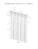
[0019] FIG. 1 shows an exemplary embodiment of the inventive securement means securing a panel of fabric to a support unit.
[0020] FIG. 2 shows a partial view of a top portion of the exemplary securement means of FIG. 1 with the panel removed from the support unit.
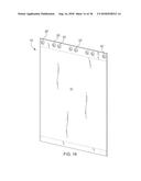
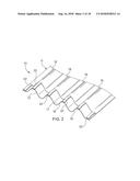
[0021] FIG. 3 shows a rear view of a panel having securement straps, which may be used as the securement means.
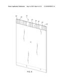
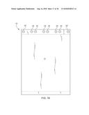
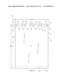
[0022] FIG. 4 shows a rear view of a panel having securement apertures, which may be used as the securement means.
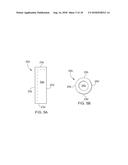
[0023] FIGS. 5A-5B show exploded views of a securement strap and a securement aperture.
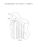
[0024] FIG. 6 shows a partial view of a panel being suspended from a support unit with a sheer suspended behind the panel.
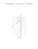
[0025] FIG. 7 shows a partial view of a pleat that may be formed by the inventive securement means.
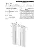
[0026] FIG. 8 shows a perspective view of an embodiment of the apparatus with the panel laid flat and with a plurality of straps as the securement means.
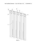
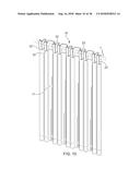
[0027] FIG. 9 shows a perspective view of an embodiment of the apparatus with the panel folded to form pleats and with a plurality of straps as the securement means.
[0028] FIG. 10 shows a perspective view of an embodiment of the apparatus with the panel depending from a support unit and with a plurality of straps as the securement means.
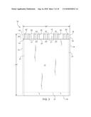
[0029] FIG. 11 shows a rear view of an embodiment of the apparatus with the panel laid flat and with a plurality of straps as the securement means.
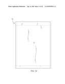
[0030] FIG. 12 shows a front view of an embodiment of the apparatus with the panel laid flat and with a plurality of straps as the securement means.
[0031] FIG. 13 shows a top and/or bottom view of an embodiment of the apparatus with the panel laid flat and with a plurality of straps as the securement means.
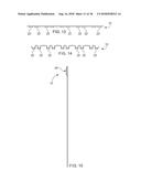
[0032] FIG. 14 shows a top and/or bottom view of an embodiment of the apparatus with the panel folded to form pleats and with a plurality of straps as the securement means.
[0033] FIG. 15 shows a left and/or right side view of an embodiment of the apparatus with the panel laid flat and with a plurality of straps as the securement means.
[0034] FIG. 16 shows a perspective view of an embodiment of the apparatus with the panel laid flat and with a plurality of apertures as the securement means.
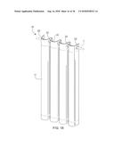
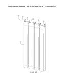
[0035] FIG. 17 shows a perspective view of an embodiment of the apparatus with the panel folded to form pleats and with a plurality of apertures as the securement means.
[0036] FIG. 18 shows a perspective view of an embodiment of the apparatus with the panel depending from a support unit and with a plurality of s apertures as the securement means.
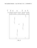
[0037] FIG. 19 shows a rear and/or front view of an embodiment of the apparatus with the panel laid flat and with a plurality of apertures as the securement means.
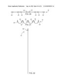
[0038] FIG. 20 shows a top and/or bottom view of an embodiment of the apparatus with the panel laid flat and with a plurality of apertures as the securement means.
[0039] FIG. 21 shows a top and/or bottom view of an embodiment of the apparatus with the panel folded to form pleats and with a plurality of apertures as the securement means.
[0040] FIG. 22 shows a left and/or right side view of an embodiment of the apparatus with the panel laid flat and with a plurality of apertures as the securement means.
DETAILED DESCRIPTION OF THE INVENTION
[0041] The following description is of an embodiment presently contemplated for carrying out the present invention. This description is not to be taken in a limiting sense, but is made merely for the purpose of describing the general principles and features of the present invention. The scope of the present invention should be determined with reference to the claims.
[0042] Referring to FIGS. 1-2, the apparatus 10 can include a securement means 20 for a panel 11 of fabric so as to facilitate the panel 11 being suspended from a support unit 1. The support unit 1 can be an elongated member, a rod, a pole, a track, etc. that can be attached to a wall or other structure associated with a window, shower, walkway, doorway, opening, framed-in unit, etc. The support unit 1 can be straight, angled, curved, curvelinear, etc. The support unit 1 can have a cross-sectional shape that is cylindrical, oval, semi-circular, cubic, hexoginal, pyramidal, etc. The support unit 1 can be fixed in length or adjustable in length (e.g., the support unit 1 can comprise two rods have a telescoping arrangement). The support unit 1 can further include a finial located at one of its distal ends. Any portion of the support unit 1 and/or finial can include an embellishment or other ornamental design. It is contemplated for the support unit 1 and the panel 11 of fabric to be used as part of a window treatment, where the panel 11 may be used as a curtain. However, the support unit 1 and the panel 11 of fabric can be used as any other type of barrier, privacy component, decorating element, etc. for a framed-in unit having an opening. The fabric may be cotton, satin, silk, plastic, acrylic, felt, wool, etc. The panel 11 can be a fabric having any density as measured by grams per square meter ("GSM").
[0043] The securement means 20 can be located on and/or in any portion of the panel 11. In some embodiments, the securement means 20 may be located on and/or in a top 12 portion of the panel 11. For example, the panel 11 can be square or rectangular, having a top 12, first and second lateral sides 13,14, and a bottom 15, where the securement means 20 is located on and/or in the top 12 of the panel 11. Further, the panel 11 can include a front face 16 (a face that faces away from the window) and a rear face 17 (a face that faces towards the window), and the securement means 20 can be located on and/or in any one of the front face 16 and rear face 17.
[0044] Referring to FIG. 3, in some embodiments, the securement means 20 can be structured to be attached (permanently or temporarily) onto the panel 11. The attachment can be by stitching, hook-and-loop fastener, button-snap, etc. For example, the securement means 20 can be at least one securement 22 that is a strap 22a, each strap 22a having a first end and a second end (see FIG. 5). The strap 22a can be attached to the panel 11 at its first and second ends so that a portion of the strap 22a between the first and second ends (i.e., a middle portion 24a) is not physically attached to the panel 11. The strap first end can be the strap top 23a and the strap second end can be the strap bottom 23a'. Alternatively, the strap first end can be the strap first lateral side 25a and the strap second end can be the strap second lateral side 25a'. The strap 22a can be attached so that the middle portion 24a buckles out and away from the panel 11 (e.g., so that the strap 22a has some play). Alternatively, the middle portion 24a can exhibit no play, and thus abut against the panel 11.
[0045] It is contemplated for the strap 22a to receive at least a portion of the support unit 1 to facilitate suspending the panel 11 therefrom (see FIG. 1). It is further contemplated for the engagement of the securement means 20 with the support unit 1 to facilitate free slidable motion of the panel 11, or any portion thereof, about the support unit 1. This may include motion about a longitudinal length 2 of the support unit 1. For example, the support unit 1 can be an elongated rod and the panel 11 can be caused to depend from the rod by sliding the rod through at least one strap 22a. The panel 11 can then be manipulated by sliding any portion of the panel 11 in the longitudinal direction 2 of the support unit 1. In some embodiments, a portion of the panel 11 can be slid toward another portion of the panel 11 to create a pleat 18 in the panel 11.
[0046] The strap 22a can be a fabric that is the same as or different from the fabric of the panel 11. The strap 22a can be made to be more rigid or less rigid that the rigidity of the panel 11. For example the strap 22a can include reinforced stitching, a stiffener, and/or a gusset to cause the strap 22a to be more rigid. The strap 22a can include reinforced stitching, a stiffener, and/or a gusset to cause the strap 22a to exhibit a particular shape, or at least have a tendency to form a particular shape.
[0047] In some embodiments, the securement means 20 can be at least one rigid element (not shown) attached to the panel 11, where the attachment can be achieved with any of the attachment techniques described above. For example, the securement means 20 can be a hook, a ring, a clamp, etc.
[0048] Referring to FIG. 4, alternatively, or in addition, the securement means 20 can be structured to be formed into a portion of the panel 11. For example, the securement means 20 can be at least one aperture 22b sized to slidably receive at least a portion of the support unit 1. It is contemplated for the aperture 22b to receive at least a portion of the support unit 1 to facilitate suspending the panel 11 therefrom (see FIG. 6). It is further contemplated for the engagement of the securement means 20 with the support unit 1 to facilitate free slidable motion of the panel 11, or any portion thereof, about the support unit 1. For example, the support unit 1 can be an elongated rod and the panel 11 can be caused to depend from the rod by sliding the rod through an aperture 22b. The panel 11 can then be manipulated by sliding any portion of the panel 11. This may include motion in the longitudinal direction 2 of the support unit 1. For example, a portion of the panel 11 can be slid to another portion of the panel 11 to create a pleat 18 in the panel 11.
[0049] Any aperture 22b can be circular, semi-circular, oval, hexoginal, square, triangular, etc. Any aperture 22b can match a shape of the longitudinal cross-sectional shape of the support unit 1 or be dissimilar in shape. Any aperture 22b can include reinforced fabric, stitching, a stiffener, a gusset, and/or a grommet on and/or around any portion of the aperture 22b. This may be done to provide added support and durability to each aperture 22b. This may also be done to provide a desired coefficient of friction between the securement means 20 and the support unit 1 (e.g., a more non-slip engagement can be generated to resist slidable motion or a more slick engagement can be generated to further facilitate slidable motion). Any securement aperture 22b can include a securement aperture top 23b, securement aperture bottom 23b', securement aperture first lateral end-point 25b, securement aperture second lateral end-point 25b', and a securement aperture center 24b (see FIG. 5).
[0050] In some embodiments, the securement means 20 can further include a clip, clamp, or other fastener (not shown) that is attachable (permanently or temporarily) to the panel 11, the strap 22a, and/or the aperture 22b. The fastener may be specifically configured for engaging a particular type of support unit 1. For example, the support unit 1 may include a track with a channel, wherein the fastener may include a bracket with a wheel that engages the channel.
[0051] In some embodiments, the securement means 20 can be an extension of fabric (i.e., fabric-extension) attached (permanently or temporarily) to at or near an edge of the panel 11. The fabric-extension can be a strip of fabric that is the same as or different from the fabric of the panel 11, where the fabric-extension is attached to (e.g., sewn, snapped, woven, attached by hook-and-loop fastener, etc.) to the panel 11. The securement means 20 can be located on and/or in a portion of the fabric-extension.
[0052] Referring back to FIGS. 3-4, in at least one embodiment, the securement means 20 may include at least one securement 22 (e.g., any of the straps 22a, apertures 22b, rigid element, clips, clamps, etc.) that is at least one of formed onto, formed into, attached to, and attachable to a portion of the panel 11. The securement means 20 can be located at a top 12 portion of the panel 11. Some embodiments can include a plurality of securements 22. Each securement 22 of the securement means 20 can be positioned along the top 12 portion so as to form an array of securements 22. Any number of securements 22 can form a set of securements 22, where the array of securements 22 can be defined by a spacing between the securements 22 of the set and a spacing between the sets of securements 22. For example, two securements 22 can form set-1, where the spacing between each securement 22 of set-1 may be d-1. An additional two securements 22 can form set-2, where the spacing between each securement 22 of set-2 may be d-2. An additional two securements 22 can form set-3, where the spacing between each securement 22 of set-3 may be d-3. An additional two securements 22 can form set-i, where the spacing between each securement 22 of set-i may be d-i, and so on. In addition, the spacing(s) between the sets can be defined as j-1, j-2, . . . j-i. Any spacing between securements 22 within a set can be the same as or different from a spacing between other securements 22 within the same set. Any spacing between securements 22 within a set can be the same as or different from a spacing between securements 22 within a different set. Any spacing between a set can be the same as or different from a spacing between another set. As noted above, any set can include any number of securements 22. For example, a set can include three securement 22, four securement 22, etc. Further, a number of securements 22 within one set can be the same as or different from a number of securements 22 of another set.
[0053] The panel 11 can include at least one lead-in securement 22'. The lead-in securement 22' can be a securement 22 that is most proximal to a lateral side 13,14 of the panel 11. Thus, with a rectangular panel 11, for example, a securement means 20 may include a plurality of securements 22 with a first lead-in securement 22' at or near the first lateral side 13 and a second lead-in securement 22' at or near the second lateral side 14. There can be multiple arrays of securements 22 to form the securement means 20, and thus there may be more than one lead-in securement 22' for a given lateral side 13,14. Therefore, the first lateral side 13 may have at least one lead-in securement 22' and the second lateral side 14 may have at least one lead-in securement 22'. The spacing(s) between a distal edge 19 of the lateral side 13,14 and a lead-in securement 22' can be defined as k-i. This distance, k-i, may also be referred to as the "projection" of the panel.
[0054] The spacings (d-i's and j-i's) can be defined by a length between central portions 24a, 24b of adjacent securements 22 or a length between lateral end-points 25a, 25b, 25a', 25b' of adjacent securements 22 (see FIGS. 5A-B). The spacings (k-i's) can be defined by a length between a central portion 24a, 24b of a lead-in securement 22' and the distal edge 19 the lateral side 13,14 most proximal to the lead-in securement 22' or a length between a lateral end-point 25a, 25b, 25a', 25b' of a lead-in securement 22' and the distal edge 19 of the lateral side 13,14 most proximal to the lead-in securement 22'.
[0055] As will be explained, the spacings (d-i's, j-i's, k-i's) can facilitate suspending the panel 11 from a support unit 1 in a stable and non-sloppy manner. Further, the spacings (d-i's, j-i's, k-i's) can allow the panel 11 to depend from the support unit 1 to generate pleating 18 without the pleating 18 being uneven or disproportionate and/or without the pleating 18 being easily disrupted or disordered. Further, the spacings (d-i's, j-i's, k-i's) can facilitate suspension of the panel 11 from the support unit 1 so that manipulation of the panel 11 would not interfere with a sheer positioned behind the panel 11.
[0056] In an exemplary embodiment, the panel 11 can be rectangular with a top 12, a bottom 15, a first lateral side 13, and a second lateral side 14. The top 12 may have a length equal to a length of the bottom 15. The first lateral side 13 may have a length equal to a length of the second lateral side 14. The lengths of the first and second lateral sides 13,14 can be greater than the lengths of the top 12 and bottom 15. Any of the top 12, the lateral sides 13,14, and/or the bottom 15 may include a hem 21. Any of the hems 21 can be a lockstitch hem. Any portion of the panel 11 can include a stiffener (e.g., Pellon.RTM. stiffener). The panel 11 can further include a front face 16 and a rear face 17. The securement means 20 may be located at or near the top 12, and may further be located at the rear face 17.
[0057] The securement means 20 can include a plurality of sets of securements 22, where each set may include at least two securements 22. The securement means 22 can further be structured as a linear array of securements 22 that run parallel with an edge of the top 12. Spacings d-i can be the same between each securement 22 of a set. Spacings j-i can be the same between each set of securements 22. Each spacing d-i can be less than each spacing j-i. The securement 22 set most proximal the first lateral side 13 may include two securements 22, and the securement 22 of that set most proximal to the first lateral side 13 can be a first lead-in securement 22'. The securement 22 set most proximal the second lateral side 14 may include two securements 22, and the securement 22 of that set most proximal to the second lateral side 14 can be the second lead-in securement 22'. The first and second lead-in securements 22' can have spacings k-i between the lead-in securement 22' and the distal edge 19 of the lateral side 13,14 most proximal to it. Each of spacings k-i for the securement means 20 can be of the same length. Each of spacings k-i for the securement means 20 may be less than any of the spacings d-i and j-i.
[0058] The spacings k-i can be minimal so that the projection (i.e., the fabric of the panel that exists between a lead-in securement 22' and the distal edge of the lateral side 13,14 it is most proximal to) is minimized. (See FIG. 6). Such an arrangement can facilitate suspending the panel 11 on a support unit 1, where the support unit 1 is mounted in front of another window treatment (e.g., a sheer) without the panel 11 making contact with the sheer. This can be achieved by minimizing the amount of fabric that exists between each lead-in securement 22' and the distal edge 19 of the lateral side 13,14 it is most proximal to, or minimizing the k-i. In other words, this fabric portion of the panel 11 (or the projection) does not make contact with the sheer. Further, the panel 11 can be manipulated without interfering with the sheer suspended behind the panel 11. Prior art systems may require an extension to the mounting brackets of the support unit 1 to move a panel further away from a sheer so as to prevent such interference, but with the presently disclosed invention such extension methods are obviated.
[0059] A securement means 20 with each spacing d-i being the same and with each spacing j-i also being the same, where each spacing d-i is less than the each of spacing j-i, can facilitate generation of a desired pleating 18 that is stable and even across the panel 11. For example, after the panel 11 is suspended from the support unit 1 and portions of the panel 11 are moved towards each other to form pleats 18, each securement 22 of the at least two-securement set can generate a natural tendency to produce a pleat 18 between the securements 22 of the set and a pleat 18 between each set, s-i, of securements 22. The spacings (d-i and j-i) can further generate a tendency for the panel 11 to maintain this pleated arrangement, even when the panel 11 is further manipulated.
[0060] Referring to FIG. 7, because the spacings d-i are equal to each other and the spacing j-i are equal to each other, each pleat 18 can have a width 18a that is even and consistent through the panel 11. In addition, the spacings d-i and j-i can be set to further facilitate non-interference with any window treatment suspended behind the panel 11. For example, the spacings d-i and j-i can be set so as to generate pleats 18 with delimited widths 18a and depths 18b. A width 18a of a pleat can be a length measured from trough to trough of the pleat 18. A depth 18b of a pleat 18 can be a length measured from a trough to a peak of a pleat 18. Thus, by setting the spacings d-i and j-i, the widths 18a and/or depths 18b of each pleat 18 can be delimited. Delimiting the depth 18b can prevent the panel 11, at the pleat peak 18c, from making contact with the sheer suspended behind the panel 11.
[0061] In some embodiments, spacings d-i may not be equal to each other, spacings j-i may not be equal to each other, and/or spacing k-i may not be equal to each other. Having any of the spacings (d-i, j-i, k-i) be unequal may be done to generate a pleating 18 that is disproportionate across the panel 11. Yet, the pleating 18 can still be stable. For example, one may want to generate pleating 18 that has wider pleats 18 and/or deeper pleats 18 at or near the lateral sides 13,14, and narrower pleats 18 and/or shallower pleats 18 at or near a center of the panel 11. This would generate a pleating that is uneven or disproportionate across the panel 11, but due to the tendency to maintain the pleating, the pleats 18 can maintain such an arrangement. Further, one of the k-i's can be greater than another k-i to generate a particular aesthetic effect or to allow for the panel 11 to make contact with the sheer at one side but prevent such contact at another side. Further, the spacings (d-i, j-i, k-i) can be set to generate a desired number of pleats 18 and/or pleats 18 at desired positions on the panel 11, as each set, s-i, of securements 22 can be used to determine the number of pleats 18 and/or determine positions on the panel 11 where the pleats 18 can have a tendency to form. Thus, the ability to generate the number of pleats 18, generate pleatings 18 at certain locations on the panel 11, delimited widths 18a and/or depths 18b of the pleats 18, and/or the tendency to maintain the pleating 18 at those widths 18a and/or depths 18b can further facilitate generating a pleating 18 with desired utilitarian or aesthetic effects. For example, a panel 11 with more pleatings 18 formed across the panel 11 or pleatings 18 that are more narrow in width 18a and greater in depth 18b may block more light as opposed to a panel 11 with less pleatings 18 across the panel 11 or pleatings 18 that are more broad in width 18a and more shallow in depth 18b.
[0062] FIG. 3 shows a non-limiting example of the apparatus 10. The panel 11 that can be rectangular with a top 12 having a length of 54 inches, a bottom 15 with a length of 54 inches, a first lateral side 13 with a length of 84 inches, and a second lateral side 14 with a length of 84 inches. The panel 11 can be a fabric with 65 GSM. The bottom 15 can include a 3-inch hem 21. The first and second lateral sides 13,14 can each include a 1-inch hem 21. The top 12 can include a 3.5-inch hem 21. The securement means 20 can be located at the rear face 11b and within the 3.5-inch hem 21 of the top 12. The securement means 20 may include five securement sets, s-i, with two securements 22,22' in each set. The securement means 20 can structured as a linear array of securements 22,22' that run parallel with an edge of the top 12. The securements 22,22' can be straps 22a attached to the rear face 17 of the panel 11, where each strap 22a can be rectangular in shape. Each strap 22a can include a strap top 23a having a length of 1 inch, a strap bottom 23a' having a length of 1 inch, and strap sides 25a, 25a' each having a length of 3.5 inches. The straps 22a can be arranged so that the strap sides 25a, 25a' are parallel with the panel lateral sides 13,14. The straps 22a can be attached to the panel 11 at the strap top 23a and the strap bottom 23a' so as to have an open middle portion 24a (e.g., a middle portion 24a that is not physically attached to the panel 11). Each strap 22a can be within an area defined by the 3.5-inch hem 21 so as to form a 3.5-inch support unit pocket. In other words, the support unit 1 can be slidably received within the securement means 20 of the 3.5-inch support unit pocket by sliding the support unit 1 within each middle portion 24a of each strap 22a. Spacings d-i can be 3 inches between each securement strap 22a of a set, s-i. Spacings j-i can be 6.75 inches between each set, s-i, of securement straps 22a. The securement strap set, s-i, most proximal to the first lateral side 13 can include two securement straps 22a, and the securement strap 22a of that set, s-i, most proximal to the first lateral side 13 can be the first lead-in securement strap 22'. The securement strap set, s-i, most proximal the second lateral side 14 can include two securement straps 22a, and the securement strap 22a of that set, s-i, most proximal to the second lateral side 14 can be the second lead-in securement strap 22'. The first and second lead-in securement straps 22' can each have spacings k-i that are 1 inch between the lead-in securement strap 22' and the distal edge 19 of the lateral side 13,14 most proximal to the lead-in securement strap 22'. The spacings (d-i's and j-i's) can be defined by a length between lateral end-points 25a, 25a' of each securement strap 22a of adjacent securements strap 22a. The spacings (k-i's) can be defined by a length between a lateral end-point 25a, 25a' of a lead-in securement strap 22' and the distal edge 19 of the lateral side 13,14 most proximal to the lead-in securement strap 22'.
[0063] FIG. 4 shows a non-limiting example of the apparatus 10. The panel 11 can be rectangular with a top 12 having a length of 54.25 inches, a bottom 15 with a length of 54.25 inches, a first lateral side 13 with a length of 84.75 inches, and a second lateral side 14 with a length of 84.75 inches. The panel 11 can be a fabric with 65 GSM. The bottom 15 can include a 3-inch hem 21. The first and second lateral sides 13,14 can include a 1-inch hem 21. The top 12 can include a 4-inch hem 21. The hemmed portion of the top 12 can further include a stiffener. The securement means 20 can be located at the rear face 17 and within the 4-inch hem 21 of the top 12. The securement means 20 may include three securement 22 sets, s-i, and two lead-in securements 22'. The securements 22,22' can be apertures 22b formed into the panel 11, where each aperture 22b may be circular shape. Any aperture 22b can further include a grommet. Each aperture 22b can be positioned within the 4-inch hem 21 so that a central portion 24b of each aperture 22b is at a mid-point between a top edge of the panel 11 and the hem 21 of the top 11. Each aperture 22b, and grommet if one is used, can be structured to slidably receive the support unit 1. The securement means 20 can be structured as a linear array of securements 22,22' that run parallel with an edge of the top 12, where the linear array may include a single lead-in securement aperture 22' adjacent the first lateral side 13, three two-securement aperture 22b sets, and a single lead-in securement 22' adjacent the second lateral side 14. Each aperture 22b can include lateral end-points 25b, 25b' on each side of the aperture 22b. Spacings d-i can be 2.5 inches between each securement aperture 22b of a set, s-i. Spacings j-i can be 6.5 inches between each set, s-i, of securements apertures 22b. The lead-in securement apertures 22' can each have a spacing k-i that ranges between 1 inch to 1.5 inches, as measured between the lead-in securement aperture 22' and the distal edge 19 of the most proximal lateral side 13,14. The spacings (d-i's and j-i's) can be defined by a length between lateral end-points 25b, 25b' of each aperture 22b of adjacent securements 22b. The spacings (k-i's) can be defined by a length between a lateral end-point 25b, 25b' of a lead-in securement aperture 22' and the distal edge 19 of the lateral side 13,14 most proximal to the lead-in securement strap 22'.
[0064] FIGS. 8-22 show various views of various embodiments of the apparatus 10.
[0065] It will be apparent to those skilled in the art that numerous modifications and variations of the described examples and embodiments are possible in light of the above teachings of the disclosure. The disclosed examples and embodiments are presented for purposes of illustration only. Other alternate embodiments may include some or all of the features disclosed herein. Therefore, it is the intent to cover all such modifications and alternate embodiments as may come within the true scope of this invention, which is to be given the full breadth thereof. Additionally, the disclosure of a range of values is a disclosure of every numerical value within that range, including the end points.
User Contributions:
Comment about this patent or add new information about this topic:
Images included with this patent application:
 |  |
 |  |
 |  |
 |  |
 |  |
 |  |
 |  |
 |  |
 |  |
 |
| New patent applications in this class: | |
| Date | Title |
|---|---|
| 2022-09-22 | Electronic device |
| 2022-09-22 | Front-facing proximity detection using capacitive sensor |
| 2022-09-22 | Touch-control panel and touch-control display apparatus |
| 2022-09-22 | Sensing circuit with signal compensation |
| 2022-09-22 | Reduced-size interfaces for managing alerts |