Patent application title: ASSEMBLY FOR DEBUGGING MODEM AND METHOD THEREOF
Inventors:
IPC8 Class: AH04B1724FI
USPC Class:
1 1
Class name:
Publication date: 2017-07-06
Patent application number: 20170195070
Abstract:
A debugging assembly includes a modem including a control unit, a switch
unit, and an RJ45 port. The control unit is coupled to the RJ45 port
through the switch unit. The control unit is configured to detect a
network connection status of the modem and transmit a control signal to
selectively couple the switch unit to pins of the RJ45 port to
selectively receive a network signal or a debugging signal.Claims:
1. A method for debugging a modem having a control unit, a switch unit,
and an RJ45 port, the method comprising: inspecting, by the control unit,
when a debugging cable is inserted into the RJ45 port of the modem, a
current network connection status of the modem; transmitting, by the
control unit, a control signal to the switch unit to selectively couple
the switch unit to corresponding pins of the RJ45 port; and selectively
receiving, by the control unit, when the switch unit is selectively
coupled to the RJ45 port, a network signal or a debugging signal.
2. The method as in claim 1, wherein: the control signal comprises a first control signal and a second control signal; when the network connection status is in a disconnection status or a first connection status, the first control signal is transmitted at a high level and the second control signal is transmitted at a low level to the switch unit to control the switch unit to couple to a first pin, a second pin, a third pin, and a sixth pin of the RJ45 port; and when the network connection status is in a second connection status, the first control signal is transmitted at a low level and the second control signal is transmitted at a high level to the switch unit to control the switch unit to couple to a fourth pin, a fifth pin, a seventh pin, and an eighth pin of the RJ45 port.
3. The method as in claim 2, wherein: the first connection status is a low-speed connection status; and the second connection status is a high-speed connection status.
4. The method as in claim 2, wherein: when the switch unit is coupled to the first pin, the second pin, the third pin, and the sixth pin of the RJ45 port, a first network signal and a second network signal are received; and when the switch unit is coupled to the fourth pin, the fifth pin, the seventh pin, and the eighth pin of the RJ45 port, the first network signal and a debugging signal are received.
5. The method as in claim 4, wherein: the first network signal is a signal transmitted in the first network status; and the second network signal is a signal transmitted in the second network status.
6. The method as in claim 1 comprising transmitting, after the modem has been debugged, a feedback result to an electronic device coupled to the modem.
7. A debugging assembly comprising: a modem comprising: a control unit; a switch unit; and an RJ45 port; wherein the control unit is coupled to the RJ45 port through the switch unit; and wherein the control unit is configured to detect a network connection status of the modem and transmit a control signal to selectively couple the switch unit to pins of the RJ45 port to selectively receive a network signal or a debugging signal.
8. The debugging assembly as in claim 7, wherein: the control signal comprises a first control signal and a second control signal; when the control unit detects that the network connection status is in a disconnection status or a first connection status, the control unit transmits the first control signal at a high level and the second control signal at a low level to the switch unit to control the switch unit to couple to a first pin, a second pin, a third pin, and a sixth pin of the RJ45 port; and when the control unit detects that the network connection status is in a second connection status, the control unit transmits the first control signal at a low level and the second control signal at a high level to the switch unit to control the switch unit to couple to a fourth pin, a fifth pin, a seventh pin, and an eighth pin of the RJ45 port.
9. The debugging assembly as in claim 7, wherein: the first connection status is a low-speed connection status; and the second connection status is a high-speed connection status.
10. The debugging assembly as in claim 7, wherein: the modem is coupled to a debugging apparatus and an electronic device by an inspection cable; and the electronic device is configured to display a feedback result of debugging the modem.
11. The debugging assembly as in claim 10, wherein: a first end of the inspection cable is coupled to the RJ45 port by a corresponding coupling head; a second end of the inspection cable is coupled to the debugging apparatus through a corresponding coupling head; and a third end of the inspection cable is coupled to the electronic device through a corresponding coupling head.
Description:
FIELD
[0001] The subject matter herein generally relates to an assembly for debugging a modem and a method thereof.
BACKGROUND
[0002] Generally, when debugging a modem during an initial design phase of the modem, a specialized port of the modem is used for debugging. When the modem is mass produced, the specialized port is usually removed. If the modem requires to be debugged again, the specialized port needs to be reattached to the modem for debugging.
BRIEF DESCRIPTION OF THE DRAWINGS
[0003] Implementations of the present technology will now be described, by way of example only, with reference to the attached figures.
[0004] FIG. 1 is a block diagram of an embodiment of a debugging assembly.
[0005] FIG. 2 is a flowchart of an embodiment of a method for debugging a modem.
DETAILED DESCRIPTION
[0006] It will be appreciated that for simplicity and clarity of illustration, where appropriate, reference numerals have been repeated among the different figures to indicate corresponding or analogous elements. In addition, numerous specific details are set forth in order to provide a thorough understanding of the embodiments described herein. However, it will be understood by those of ordinary skill in the art that the embodiments described herein can be practiced without these specific details. In other instances, methods, procedures and components have not been described in detail so as not to obscure the related relevant feature being described. The drawings are not necessarily to scale and the proportions of certain parts may be exaggerated to better illustrate details and features. The description is not to be considered as limiting the scope of the embodiments described herein.
[0007] Several definitions that apply throughout this disclosure will now be presented.
[0008] The term "coupled" is defined as connected, whether directly or indirectly through intervening components, and is not necessarily limited to physical connections. The connection can be such that the objects are permanently connected or releasably connected. The term "comprising" means "including, but not necessarily limited to"; it specifically indicates open-ended inclusion or membership in a so-described combination, group, series and the like.
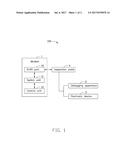
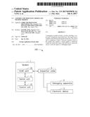
[0009] FIG. 1 illustrates an embodiment of a debugging assembly 100. The debugging assembly 100 can include a modem 1, a debugging apparatus 2, and an electronic device 3. In at least one embodiment, the modem 1 is coupled to the debugging apparatus 2 and the electronic device 3 through an inspection cable 4. The debugging apparatus 2 can transmit a debugging signal to the modem 1 to debug the modem 1. The electronic device 3 can include a display (not shown) to display a feedback result of debugging the modem 1. In at least one embodiment, the electronic device 3 can be a personal computer, a laptop computer, or the like. A first end of the inspection cable 4 can be coupled to the modem 1 through a corresponding coupling head. A second end of the inspection cable 4 can be coupled to the debugging apparatus 2 through a corresponding coupling head. A third end of the inspection cable 4 can be coupled to the electronic device 3 through a corresponding coupling head.
[0010] In at least one embodiment, the modem 1 can include an RJ45 port 10, a switch unit 11, and a control unit 12. The control unit 12 can be coupled to the RJ45 port 10 through the switch unit 11. The switch unit 11 is used for controlling the RJ45 port 10 to selectively receive a network signal or a debugging signal. In at least one embodiment, a first end of the switch unit 11 is coupled to a GPIO port of the modem 1 to receive a control signal from the control unit 12, and another end of the switch unit 11 is coupled to the RJ45 port 10. In at least one embodiment, the switch unit 11 can be an integrated circuit, such as an AS179-92LF chip.
[0011] The RJ45 port 10 can include eight pins. A first pin, a second pin, a third pin, and a sixth pin of the RJ45 port 10 can be a TX+ pin, a TX- pin, an RX+ pin, and an RX- pin, respectively. "TX" represents transmitting data, and "RX" represents receiving data. A fourth pin, a fifth pin, a seventh pin, and an eighth pin of the RJ45 port 10 are standby pins. In at least one embodiment, the fourth, fifth, seventh, and eighth pins are used for transmitting the debugging signal. Thus, a separate debugging port is not required to be attached to the modem 1 to debug the modem 1.
[0012] The control unit 12 can detect a current network connection status of the modem 1 to selectively couple the switch unit 11 to the RJ45 port 10, thereby selectively receiving the network signal or the debugging signal. The control unit 12, upon receiving the debugging signal, can debug the modem 1 and transmit the feedback result of debugging the modem 1 to the electronic device 3.
[0013] In at least one embodiment, the control signal transmitted by the control unit 12 can include a first control signal and a second control signal. When the control unit 12 detects that the network connection status is in a disconnection status or a first connection status, the control unit 12 transmits the first control signal at a high level and the second control signal at a low level to the switch unit 11 to control the switch unit 11 to couple to the first pin, the second pin, the third pin, and the sixth pin of the RJ45 port 10. When the network connection status is in the disconnection status or the first connection status, the control unit 12 receives a first network signal and a second network signal. When the control unit 12 detects that the network connection status is in a second connection status, the control unit 12 transmits the first control signal at a low level and the second control signal at a high level to the switch unit 11 to control the switch unit 11 to couple to the fourth pin, the fifth pin, the seventh pin, and the eighth pin of the RJ45 port 10. When the network connection status is in the second connection status, the control unit 12 receives the first network signal and the debugging signal.
[0014] In at least one embodiment, the first connection status is a low-speed connection status (100 megabytes/second or lower), and the second connection status is a high-speed connection status (1000 megabytes/second or higher). The first network signal is transmitted in the first network connection status, and the second network signal is transmitted in the second network connection status.
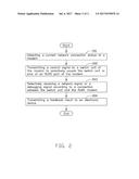
[0015] FIG. 2 illustrates a flowchart of an exemplary method for debugging a modem. The example method is provided by way of example, as there are a variety of ways to carry out the method. The method described below can be carried out using the configurations illustrated in FIG. 1, for example, and various elements of the figure are referenced in explaining the example method. Each block shown in FIG. 1 represents one or more processes, methods, or subroutines carried out in the example method. Furthermore, the illustrated order of blocks is by example only, and the order of the blocks can be changed. Additional blocks can be added or fewer blocks can be utilized, without departing from this disclosure. The example method can begin at block 201.
[0016] At block 201, when a control unit of the modem detects that an inspection cable has been inserted into an RJ45 port of the modem, the control unit detects a current network connection status of the modem. The network connection status can be a disconnection status, a first connection status, or a second connection status. In at least one embodiment, the first connection status is a low-speed connection status (100 megabytes/second or lower), and the second connection status is a high-speed connection status (1000 megabytes/second or higher).
[0017] At block 202, the control unit can transmit a control signal to a switch unit of the modem to selectively couple the switch unit to pins of the RJ45 port. The control signal can include a first control signal and a second control signal. When the control unit detects that the network connection status is in a disconnection status or a first connection status, the control unit transmits the first control signal at a high level and the second control signal at a low level to the switch unit to control the switch unit to couple to a first pin, a second pin, a third pin, and a sixth pin of the RJ45 port. When the control unit detects that the network connection status is in a second connection status, the control unit transmits the first control signal at a low level and the second control signal at a high level to the switch unit to control the switch unit to couple to a fourth pin, a fifth pin, a seventh pin, and an eighth pin of the RJ45 port.
[0018] At block 203, the control unit can selectively receive a network signal or a debugging signal. When the network connection status is in the disconnection status or the first connection status, the control unit receives a first network signal and a second network signal. When the network connection status is in the second connection status, the control unit receives the first network signal and the debugging signal. The first network signal is transmitted in the first network connection status, and the second network signal is transmitted in the second network connection status.
[0019] At block 204, the control unit transmits a feedback result to an electronic device coupled to the modem.
[0020] The embodiments shown and described above are only examples. Even though numerous characteristics and advantages of the present technology have been set forth in the foregoing description, together with details of the structure and function of the present disclosure, the disclosure is illustrative only, and changes may be made in the detail, including in matters of shape, size and arrangement of the parts within the principles of the present disclosure up to, and including, the full extent established by the broad general meaning of the terms used in the claims.
User Contributions:
Comment about this patent or add new information about this topic:
Images included with this patent application:
 |  |
 |
| New patent applications in this class: | |
| Date | Title |
|---|---|
| 2022-09-22 | Electronic device |
| 2022-09-22 | Front-facing proximity detection using capacitive sensor |
| 2022-09-22 | Touch-control panel and touch-control display apparatus |
| 2022-09-22 | Sensing circuit with signal compensation |
| 2022-09-22 | Reduced-size interfaces for managing alerts |