Patent application title: COLLAPSIBLE CUP ASSEMBLY
Inventors:
IPC8 Class: AB65D2108FI
USPC Class:
1 1
Class name:
Publication date: 2017-06-29
Patent application number: 20170183123
Abstract:
A collapsible cup assembly includes a cup that may contain a food item.
The cup is positionable in a collapsed position and an extended position.
A lid is removably coupled to the cup such that the lid closes the cup. A
pair of clips is provided and each of the clips is coupled to the lid. A
utensil is provided. The utensil may be manipulated thereby facilitating
the food item to be consumed. The utensil is positionable between the
clips such that the clips removably retain the utensil on the lid.Claims:
1. A collapsible cup assembly comprising: a cup being configured to
contain a food item, said cup has a bottom wall and a peripheral wall
extending upwardly from said bottom wall, said peripheral wall being
coextensive with an outer edge of said bottom wall, said peripheral wall
having a distal edge with respect to said bottom wall, said distal edge
defining an opening into said cup, said peripheral wall having a lip
extending outwardly from said distal edge, said lip being coextensive
with said distal edge, said peripheral wall being pleated between said
bottom wall and said distal edge wherein said cup is positionable in a
collapsed position and an extended position, wherein said distal edge is
urged downwardly toward said bottom wall when said cup is positioned in
said collapsed position, said distal edge being urged upwardly from said
bottom wall when said cup is positioned in said extended position; a lid
being removably coupled to said cup such that said lid closes said cup,
said lid has a top wall and a perimeter wall extending away from said top
wall, said perimeter wall being coextensive with an outer edge of said
top wall, said perimeter wall having an inner surface and a distal edge
with respect to said top wall, said top wall having a bottom surface,
said top wall has an aperture extending therethrough wherein said
aperture is configured to have a straw extended therethrough; a pair of
clips, each of said clips being coupled to said lid; and a utensil being
configured to be manipulated thereby facilitating the food item to be
consumed, said utensil being positionable between said clips such that
said clips removably retain said utensil on said lid.
2. (canceled)
3. (canceled)
4. The assembly according to claim 1, wherein further comprising said inner surface having a groove extending outwardly therein, said groove being coextensive with said distal edge corresponding to said lid.
5. The assembly according to claim 4, wherein: said cup has a lip; and said lip on said cup frictionally engaging said groove when said lid is positioned on said cup such that said lid is removably retained on said cup.
6. The assembly according to claim 1, wherein said lid has a top wall, said top wall having a bottom surface; and each of said clips has a leg and a foot, said leg of each of said clips being coupled to said bottom surface of said top wall, said clips being spaced apart from each other having said foot of each of said clips being directed toward each other.
7. The assembly according to claim 1, wherein said utensil has a scoop and a handle, said handle being hingedly coupled to said scoop, said utensil being positionable in an extended position having said handle extending away from said scoop, said utensil being positionable in a folded position having said handle lying on said scoop.
8. A collapsible cup assembly comprising: a cup being configured to contain a food item, said cup having a bottom wall and a peripheral wall extending upwardly from said bottom wall, said peripheral wall being coextensive with an outer edge of said bottom wall, said peripheral wall having a distal edge with respect to said bottom wall, said distal edge defining an opening into said cup, said peripheral wall having a lip extending outwardly from said distal edge, said lip being coextensive with said distal edge, said peripheral wall being pleated between said bottom wall and said distal edge, said cup being positionable in a collapsed position having said distal edge being urged downwardly toward said bottom wall, said cup being positionable in an extended position having said distal edge being urged upwardly from said bottom wall; a lid being removably coupled to said cup such that said lid closes said cup, said lid having a top wall and a perimeter wall extending away from said top wall, said perimeter wall being coextensive with an outer edge of said top wall, said perimeter wall having an inner surface and a distal edge with respect to said top wall, said top wall having a bottom surface, said inner surface having a groove extending outwardly therein, said groove being coextensive with said distal edge corresponding to said lid, said lip on said cup frictionally engaging said groove when said lid is positioned on said cup such that said lid is removably retained on said cup, said top wall having an aperture extending therethrough wherein said aperture is configured to have a straw extended therethrough; a pair of clips, each of said clips having a leg and a foot, said leg of each of said clips being coupled to said bottom surface of said top wall, said clips being spaced apart from each other having said foot of each of said clips being directed toward each other; and a utensil being configured to be manipulated thereby facilitating the food item to be consumed, said utensil having a scoop and a handle, said handle being hingedly coupled to said scoop, said utensil being positionable in an extended position having said handle extending away from said scoop, said utensil being positionable in a folded position having said handle lying on said scoop, said utensil being positionable between said clips when said utensil is positioned in said folded position such that said clips removably retains said utensil on said lid.
Description:
BACKGROUND OF THE DISCLOSURE
Field of the Disclosure
[0001] The disclosure relates to cup devices and more particularly pertains to a new cup device for reducing storage space associated with a cup.
SUMMARY OF THE DISCLOSURE
[0002] An embodiment of the disclosure meets the needs presented above by generally comprising a cup that may contain a food item. The cup is positionable in a collapsed position and an extended position. A lid is removably coupled to the cup such that the lid closes the cup. A pair of clips is provided and each of the clips is coupled to the lid. A utensil is provided. The utensil may be manipulated thereby facilitating the food item to be consumed. The utensil is positionable between the clips such that the clips removably retain the utensil on the lid.
[0003] There has thus been outlined, rather broadly, the more important features of the disclosure in order that the detailed description thereof that follows may be better understood, and in order that the present contribution to the art may be better appreciated. There are additional features of the disclosure that will be described hereinafter and which will form the subject matter of the claims appended hereto.
[0004] The objects of the disclosure, along with the various features of novelty which characterize the disclosure, are pointed out with particularity in the claims annexed to and forming a part of this disclosure.
BRIEF DESCRIPTION OF THE DRAWINGS
[0005] The disclosure will be better understood and objects other than those set forth above will become apparent when consideration is given to the following detailed description thereof. Such description makes reference to the annexed drawings wherein:
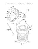
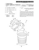
[0006] FIG. 1 is a top perspective view of a collapsible cup assembly according to an embodiment of the disclosure.
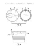
[0007] FIG. 2 is a front view of an embodiment of the disclosure in an extended position.
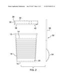
[0008] FIG. 3 is a bottom view of an embodiment of the disclosure.
[0009] FIG. 4 is a front view of an embodiment of the disclosure in a collapsed position.
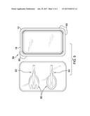
[0010] FIG. 5 is a perspective view of an alternative embodiment of the disclosure.
DESCRIPTION OF THE PREFERRED EMBODIMENT
[0011] With reference now to the drawings, and in particular to FIGS. 1 through 5 thereof, a new cup device embodying the principles and concepts of an embodiment of the disclosure and generally designated by the reference numeral 10 will be described.
[0012] As best illustrated in FIGS. 1 through 5, the collapsible cup assembly 10 generally comprises a cup 12 that may contain a food item 14. The cup 12 has a bottom wall 16 and a peripheral wall 18 extending upwardly from the bottom wall 16. The peripheral wall 18 is coextensive with an outer edge 20 of the bottom wall 16 and the peripheral wall 18 has a distal edge 22 with respect to the bottom wall 16. The distal edge 22 defines an opening 24 into the cup 12.
[0013] The peripheral wall 18 has a lip 26 extending outwardly from the distal edge 22 and the lip 26 is coextensive with the distal edge 22. The peripheral wall 18 is pleated between the bottom wall 16 and the distal edge 22. Thus, the cup 12 is positionable in a collapsed position having the distal edge 22 being urged downwardly toward the bottom wall 16. The cup 12 is positionable in an extended position having the distal edge 22 being urged upwardly from the bottom wall 16.
[0014] A lid 28 is removably coupled to the cup 12 such that the lid 28 closes the cup 12. The lid 28 has a top wall 30 and a perimeter wall 32 extending away from the top wall 30. The perimeter wall 32 is coextensive with an outer edge 34 of the top wall 30. The perimeter wall 32 has an inner surface 36 and distal edge 38 with respect to the top wall. The top wall 30 has a bottom surface 40.
[0015] The inner surface 36 has a groove 42 extending outwardly therein. The groove 42 is coextensive with the distal edge 38 corresponding to the lid 28. The lip 26 on the cup 12 frictionally engages the groove 42 when the lid 28 is positioned on the cup. Thus, the lid 28 is removably retained on the cup 12. The top wall 30 has an aperture 44 extending therethrough and the aperture 44 may have a straw extended therethrough.
[0016] A pair of clips 46 is provided and each of the clips 46 has a leg 48 and a foot 50. The leg 48 of each of the clips 46 is coupled to the bottom surface 40 of the top wall 30. The clips 46 are spaced apart from each other. The foot 50 of each of the clips 46 is directed toward each other.
[0017] A utensil 52 is provided and the utensil 52 may be manipulated thereby facilitating the food item to be consumed. The utensil 52 has a scoop 54 and a handle 56 and the handle 56 is hingedly coupled to the scoop 54. The utensil 52 is positionable in an extended position having the handle 56 extending away from the scoop 54. The utensil 52 is positionable in a folded position having the handle 56 lying on the scoop 54. The utensil 52 is positionable between the clips 46 when the utensil 52 is positioned in the folded position. Thus, clips 46 removably retain the utensil 52 on the lid. The utensil 52 may be a spoon or the like.
[0018] In an alternative embodiment 58 as shown in FIGS. 5, the peripheral wall 18 of the cup 12 may have a plurality of intersecting sides 60. Thus, the cup 12 may have a rectangular shape. A first set of the clips 62 and a second set of the clips 64 may be provided. Additionally, a pair of utensils 66 may be provided. Each of the pair of utensils 66 may be removably retained in an associated one of the first set of clips 62 and the second set of clips 64. One of the pair of utensils 66 may comprise a spoon or the like and one of the pair of utensils 66 may comprise a fork or the like.
[0019] In use, the cup 12 is positioned in the collapsed position thereby facilitating the cup 12 to be transported or stored while minimizing the space occupied by the cup 12. The cup 12 is positioned in the extended position and the food item 14 is placed in the cup 12. The lid 28 is positioned on the cup 12 and the cup 12 is transported. The lid 28 is removed from the cup 12 and the utensil 52 is removed from the clips 46. The utensil 52 is positioned in the extended position and the food item 14 is consumed. The utensil 52 is positioned in the folded position and the utensil 52 is positioned in the clips 46 when the utensil 52 is not being used.
[0020] With respect to the above description then, it is to be realized that the optimum dimensional relationships for the parts of an embodiment enabled by the disclosure, to include variations in size, materials, shape, form, function and manner of operation, assembly and use, are deemed readily apparent and obvious to one skilled in the art, and all equivalent relationships to those illustrated in the drawings and described in the specification are intended to be encompassed by an embodiment of the disclosure.
[0021] Therefore, the foregoing is considered as illustrative only of the principles of the disclosure. Further, since numerous modifications and changes will readily occur to those skilled in the art, it is not desired to limit the disclosure to the exact construction and operation shown and described, and accordingly, all suitable modifications and equivalents may be resorted to, falling within the scope of the disclosure. In this patent document, the word "comprising" is used in its non-limiting sense to mean that items following the word are included, but items not specifically mentioned are not excluded. A reference to an element by the indefinite article "a" does not exclude the possibility that more than one of the element is present, unless the context clearly requires that there be only one of the elements.
User Contributions:
Comment about this patent or add new information about this topic:
Images included with this patent application:
 |  |
 |  |
 |
| New patent applications in this class: | |
| Date | Title |
|---|---|
| 2022-09-22 | Electronic device |
| 2022-09-22 | Front-facing proximity detection using capacitive sensor |
| 2022-09-22 | Touch-control panel and touch-control display apparatus |
| 2022-09-22 | Sensing circuit with signal compensation |
| 2022-09-22 | Reduced-size interfaces for managing alerts |