Patent application title: MULTIPLE ACCESS SYSTEM FOR MULTIPLE USERS TO USE THE SAME SIGNATURE
Inventors:
IPC8 Class: AH04W7204FI
USPC Class:
1 1
Class name:
Publication date: 2017-06-08
Patent application number: 20170164369
Abstract:
A multiple access communication system in which receiving devices
equipped with a method of differentiating signals from multiple users
assigned with the same signature, the method comprising steps of
determining a plurality of hypothetical signal levels according to a
plurality of channel information; obtaining a pre-processed signal
according to a received signal received by the receiving device, wherein
the pre-processed signal comprises a mixture of a plurality of
transmitted signals, and the transmitted signals are generated according
to a plurality of signatures and encoded according to a plurality of data
signals; calculating a plurality of symbol-level probabilities according
to the pre-processed signal and the hypothetical signal levels, wherein
the number of signatures may be less than the number of users; obtaining
a plurality of log-likelihood ratios, corresponding to the users, and
generating a plurality of decoded signals corresponding to the plurality
of data signals according to the log-likelihood ratios.Claims:
1. A method of differentiating signals from multiple users, utilized in a
receiving device within a multiple access communication system, method of
differentiating signals from multiple users assigned with the same
signature, the method comprising steps of determining a plurality of
hypothetical signal levels according to a plurality of channel
information; obtaining a pre-processed signal according to a received
signal received by the receiving device, wherein the pre-processed signal
comprises a mixture of a plurality of transmitted signals from the
plurality of transmitting devices, and the plurality of transmitted
signals are generated according to a plurality of signatures and encoded
according to a plurality of data signals; calculating a plurality of
symbol-level probabilities according to the pre-processed signal and the
hypothetical signal levels, wherein the number of signatures is less than
the number of users; obtaining a plurality of log-likelihood ratios
corresponding to the plurality of users, and generating a plurality of
decoded signals corresponding to the plurality of data signals according
to the plurality of log-likelihood ratios.
2. The method of claim 1, wherein the step of determining the plurality of hypothetical signal levels according to the plurality channel information comprises: obtaining the channel coefficients according the channel information.
3. The method of claim 1, wherein the step of obtaining the pre-processed signal according to the received signal comprises: obtaining the pre-processed signal by subtracting an estimated interference-plus-noise level from the received signal.
4. The method of claim 1, wherein the step of obtaining the pre-processed signal according to the received signal comprises: obtaining the pre-processed signal by multiplying the received signal by a certain signature through a correlating unit.
5. The method of claim 1, wherein the certain signature is an interleaver, and the multiple access communication system is an interleave-division multiple access (IDMA) system.
6. The method of claim 1, wherein the certain signature is a spreading code, and the multiple access communication system is a code-division multiple access (CDMA) system.
7. The method of claim 1, wherein the user assigned with a unique signature is a degenerate case of multiple users assigned with the same signature.
8. The method of claim 1, wherein the step of calculating the plurality of log-likelihood ratios corresponding to the plurality of users according to the pre-processed signal and the plurality of hypothetical signal levels comprises: calculating a plurality of symbol-level probabilities of the plurality of hypothetical signal levels given the pre-processed signal are obtained at the receiving device; calculating a plurality of bit-level probabilities corresponding to the plurality of users according to the plurality of symbol-level probabilities; and calculating the plurality of log-likelihood ratios corresponding to the plurality of users according to the plurality of bit-level probabilities.
9. The method of claim 8, wherein the step of calculating the plurality of symbol-level probabilities comprises: calculating symbol-level probabilities of hypothetical signal levels given the pre-processed signals are obtained at the receiving device according to a priori probabilities; wherein a priori probabilities are obtained from the receiving device in an earlier iteration.
10. A receiving device, comprising: a multilevel detection unit, configured to perform following steps: determining a plurality of hypothetical signal levels according to a plurality of channel information; obtaining a pre-processed signal according to a received signal received by the receiving device, wherein the pre-processed signal comprises a mixture of a plurality of transmitted signals from the plurality of transmitting devices, and the plurality of transmitted signals are generated according to a plurality of signatures and encoded according to a plurality of data signals; calculating a plurality of symbol-level probabilities according to the pre-processed signal and the hypothetical signal levels, wherein a number of signatures is less than a number of users; and obtaining a plurality of log-likelihood ratios corresponding to the plurality of users; a plurality of decoding units, configured to generate a plurality of decoded signals corresponding to the plurality of data signals according to the plurality of log-likelihood ratios.
11. The receiving device of claim 10, wherein the multilevel detection unit is configured to perform the step of determining the plurality of hypothetical signal levels according to the plurality channel information comprises: obtaining the channel coefficients according the channel information.
12. The receiving device of claim 10, wherein the pre-processed signal is obtained by subtracting an estimated interference-plus-noise level from the received signal.
13. The receiving device of claim 10, further comprising a correlating unit, wherein the step of obtaining the pre-processed signal according to the received signal comprises: obtaining the pre-processed signal by multiplying the received signal by a certain signature through a correlator unit.
14. The receiving device of claim 10, wherein the certain signature is an interleaver.
15. The receiving device of claim 10, wherein the certain signature is a spreading code.
16. The receiving device of claim 10, wherein the user assigned with a unique signature is a degenerate case of multiple users assigned with the same signature.
17. The receiving device of claim 10, wherein the multilevel detection unit is further configured to perform following steps, for calculating the plurality of log-likelihood ratios corresponding to the plurality of users according to the pre-processed signal and the plurality of hypothetical signal levels: calculating a plurality of symbol-level probabilities of the plurality of hypothetical signal levels given the pre-processed signal are obtained at the receiving device; calculating a plurality of bit-level probabilities corresponding to the plurality of users according to the plurality of symbol-level probabilities; and calculating the plurality of log-likelihood ratios corresponding to the plurality of users according to the plurality of bit-level probabilities.
18. The receiving device of claim 10, wherein the step of calculating the plurality of symbol-level probabilities comprises: calculating symbol-level probabilities of hypothetical signal levels given the pre-processed signals are obtained at the receiving device according to a priori probabilities; wherein a priori probabilities are obtained from the receiving device in an earlier iteration.
Description:
CROSS REFERENCE TO RELATED APPLICATIONS
[0001] This application claims the benefit of U.S. provisional application No. 62/261,892, filed on Dec. 2, 2015 and U.S. provisional application No. 62/355,320, filed on Jun. 27, 2016, which is incorporated herein by reference.
BACKGROUND OF THE INVENTION
[0002] 1. Field of the Invention
[0003] The present invention relates to a multiple access system in which some users can share the same signature by using a method for the receiving device to differentiate signals from multiple users using the same signature, and more particularly, to a system with receiving devices capable of differentiating signals from multiple users which use a common signature.
[0004] 2. Description of the Prior Art
[0005] In the multiple access communication system, such as the code-division multiple access (CDMA) system and the interleaver-division multiple access (IDMA) system, each user employs a unique signature for transmission and the receiver can recover the message of each user through the unique signature. However, the number of signatures in the multiple-access communication system may be limited. For example, in the CDMA system, the signature is a spreading code, and the number of distinct spreading codes is limited by a spreading code length. In the IDMA system, the signature is its interleaver, and the number of distinct interleavers is limited by the interleaver size. In such a situation, the number of users in the multiple access communication system (either in the IDMA system or in the CDMA system) is limited if a unique signature for each user is required.
[0006] Therefore, it is necessary to improve the prior art.
SUMMARY OF THE INVENTION
[0007] It is therefore a primary objective of the present invention to provide a system in which receiving devices employing a method to improve over disadvantages of the prior art.
[0008] An embodiment of the present invention discloses a multiple access communication system in which receiving devices equipped with a method of differentiating signals from multiple users assigned with the same signature, the method comprising steps of determining a plurality of hypothetical signal levels according to a plurality of channel information; obtaining a pre-processed signal according to a received signal received by the receiving device, wherein the pre-processed signal comprises a mixture of a plurality of transmitted signals from the plurality of transmitting devices, and the plurality of transmitted signals are generated according to a plurality of signatures and encoded according to a plurality of data signals; calculating a plurality of preliminary symbol-level probabilities according to the pre-processed signal and the hypothetical signal levels, wherein the number of signatures may be less than the number of users; obtaining a plurality of log-likelihood ratios (or the associated bit-level probabilities), corresponding to the plurality of users, and generating a plurality of detected/decoded signals corresponding to the plurality of data signals according to the plurality of log-likelihood ratios.
[0009] An embodiment of the present invention further discloses a receiving device comprising a multilevel detection unit, configured to perform steps of determining a plurality of hypothetical signal levels according to a plurality of channel information; obtaining a pre-processed signal according to a received signal received by the receiving device, wherein the pre-processed signal comprises a mixture of a plurality of transmitted signals from the plurality of transmitting devices, and the plurality of transmitted signals are generated according to a plurality of signatures and encoded according to a plurality of data signals; calculating a plurality of preliminary symbol-level probabilities according to the pre-processed signal and the hypothetical signal levels, wherein the number of signatures may be less than the number of users; obtaining a plurality of log-likelihood ratios (or the associated bit-level probabilities), corresponding to the plurality of users, and generating a plurality of detected/decoded signals corresponding to the plurality of data signals according to the plurality of log-likelihood ratios.
[0010] These and other objectives of the present invention will no doubt become obvious to those of ordinary skill in the art after reading the following detailed description of the preferred embodiment that is illustrated in the various figures and drawings.
BRIEF DESCRIPTION OF THE DRAWINGS
[0011] FIG. 1 is a schematic diagram of a multiple access communication system according to an embodiment of the present invention.
[0012] FIG. 2 is a schematic diagram of a decoding process according to an embodiment of the present invention.
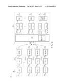
[0013] FIG. 3 is a schematic diagram of a multiple access communication system according to an embodiment of the present invention.
[0014] FIG. 4 is a schematic diagram of a decoding process according to an embodiment of the present invention.
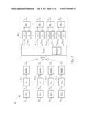
[0015] FIG. 5 is a schematic diagram of a multiple access communication system according to an embodiment of the present invention.
[0016] FIG. 6 is a schematic diagram of a decoding process according to an embodiment of the present invention.
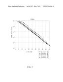
[0017] FIG. 7 illustrates performance curves of bit error rate for the multiple access communication systems of the present invention.
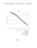
[0018] FIG. 8 illustrates performance curves of bit error rate for the multiple access communication systems of the present invention.
DETAILED DESCRIPTION
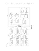
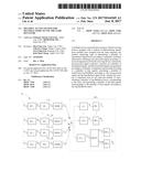
[0019] Please refer to FIG. 1, which is a schematic diagram of a multiple access communication system 10 according to an embodiment of the present invention. The multiple access communication system 10 is a code-division multiple access (CDMA) system. The multiple access communication system 10 comprises a receiving device RX.sub.1 and a plurality of transmitting devices TX.sub.11, . . . , TX.sub.1K, TX.sub.1A and TX.sub.1B. The transmitting device TX.sub.1k comprises an encoding unit ED.sub.k, a spreading unit SU.sub.k and a modulation unit MOD.sub.k, where k represents a user index ranging from 1 to K. Similarly, the transmitting device TX.sub.1A comprises an encoding unit ED.sub.A, a spreading unit SU.sub.A and a modulation unit MOD.sub.A, and the transmitting device TX.sub.1B comprises an encoding unit ED.sub.B, a spreading unit SU.sub.B and a modulation unit MOD.sub.B. The receiving device RX.sub.1 comprises correlating units CU.sub.1, . . . , CU.sub.K, a correlating unit CU.sub.m, decoding units DU.sub.1, . . . , DU.sub.K, a decoding unit DU.sub.A, a decoding unit DU.sub.B, and a multilevel detection unit MLDT.
[0020] Among the transmitting devices TX.sub.11, . . . , TX.sub.1K, each transmitting device is assigned with a unique spreading code as a signature for differentiating different users at the receiving device RX.sub.1. In other words, the spreading units SU.sub.1, . . . , SU.sub.K utilize different spreading codes s.sub.1, . . . , s.sub.K to generate spread signals x.sub.11, . . . , x.sub.1K. At the receiving device RX.sub.1, the correlating units CU.sub.1, . . . , CU.sub.K are configured to correlate a received signal r.sub.1 with the spreading codes s.sub.1, . . . , s.sub.x, such that estimated signals {circumflex over (b)}.sub.1, . . . , {circumflex over (b)}.sub.K are generated and the decoding units DU.sub.1, . . . , DU.sub.K may generate decoded signals {circumflex over (d)}.sub.1, . . . , {circumflex over (d)}.sub.K according to the estimated signals {circumflex over (b)}.sub.1, . . . , {circumflex over (b)}.sub.K. The decoded signals {circumflex over (d)}.sub.1, . . . , {circumflex over (d)}.sub.K are corresponding to data signals d.sub.1, . . . , d.sub.K of the transmitting devices TX.sub.11, . . . , TX.sub.1K, and the estimated signals {circumflex over (b)}.sub.1, . . . , {circumflex over (b)}.sub.K are corresponding to encoded signal b.sub.1, . . . , b.sub.K, which are encoded by encoding units EU.sub.1, . . . , EU.sub.K, where the encoding units EU.sub.1, . . . , EU.sub.K may be forward error correction (FEC) encoder.
[0021] In addition, the spreading units SU.sub.A and SU.sub.B utilize another spreading code s.sub.m to generate spread signals x.sub.1A and x.sub.1B. Note that, the spreading units SU.sub.A and SU.sub.B use the same spreading code (i.e., s.sub.m) to generate the spread signals x.sub.1A and x.sub.1B. At the receiving device RX.sub.1, the correlating unit CU.sub.m is configured to correlate the received signal r.sub.1 with the spreading code s.sub.m, to generate a pre-processed signal {circumflex over (b)}.sub.AB. To differentiate data signals d.sub.A and d.sub.B from the transmitting device TX.sub.1A and TX.sub.1B, the multilevel detection unit MLDT is configured to generate a set of preliminary symbol-level probabilities {p.sub.q} and log-likelihood ratios (LLRs) e.sub.LLR,A and e.sub.LLR,B corresponding to a user A and a user B according to the pre-processed signal {circumflex over (b)}.sub.AB, and the decoding unit DU.sub.A is configured to generate a decoded signal {circumflex over (d)}.sub.A corresponding to the data signal d.sub.A of the transmitting device TX.sub.1A, and the decoding unit DU.sub.B is configured to generate a decoded signal {circumflex over (d)}.sub.B corresponding to the data signal d.sub.B of the transmitting device TX.sub.1B, such that the data signals d.sub.A and d.sub.B of the transmitting device TX.sub.1A (user A) and the transmitting device TX.sub.1B (user B) are differentiated and successfully decoded at the receiving device RX.sub.1.
[0022] The received signal r.sub.1 at the receiving device RX.sub.1 may be expressed as
r 1 = k = 1 K h k y 1 k + h A y 1 A + h B y 1 B + w , ##EQU00001##
where w represents a Gaussian noise with variance .sigma..sup.2, signals y.sub.11, . . . , y.sub.1K, y.sub.1A and y.sub.1B represent transmitted signals transmitted by the transmitting devices TX.sub.11, . . . , TX.sub.1K, TX.sub.1A, TX.sub.1B, and h.sub.1, . . . , h.sub.K, h.sub.A and h.sub.B represent channel coefficients between the receiving device RX.sub.1 and the transmitting devices TX.sub.11, . . . , TX.sub.1K, TX.sub.1A, TX.sub.1B. More specifically, for the j.sup.th chip, the received signal r.sub.1(j) may be expressed as
r 1 ( j ) = k = 1 K h k y 1 k ( j ) + h A y 1 A ( j ) + h B y 1 B ( j ) + w ( j ) . ##EQU00002##
In addition, the transmitted signals y.sub.11, . . . , y.sub.1K are generated according to the spreading codes s.sub.1, . . . , s.sub.K, and the transmitted signals y.sub.1A and y.sub.1B are generated according to the spreading code s.sub.m. Note that, the spreading codes s.sub.1, . . . , s.sub.K and s.sub.m are orthogonal to each other or are correlated with each other with low correlation. Therefore, after the correlating unit CU.sub.m correlates the received signal r.sub.1 with the spreading code s.sub.m, the term
k = 1 K h k y 1 k ##EQU00003##
would be significantly eliminated, and the pre-processed signal {circumflex over (b)}.sub.AB may be expressed as {circumflex over (b)}.sub.AB=h.sub.Ay.sub.1A+h.sub.By.sub.1B+n.sub.AB, where n.sub.AB is related to the Gaussian noise w and the remaining interference from
k = 1 K h k y 1 k . ##EQU00004##
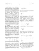
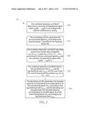
[0023] Please refer to FIG. 2, which is a schematic diagram of a detection/decoding process 20 according to an embodiment of the present invention. The detection/decoding process 20 is executed by the receiving device RX.sub.1, to differentiate and successfully decode the data signals d.sub.A and d.sub.B as the decoded signals {circumflex over (d)}.sub.A and {circumflex over (d)}.sub.B. The decoding process 20 comprises following steps:
[0024] Step 200: The multilevel detection unit MLDT determines a plurality of hypothetical signal levels s.sub.AB(0), . . . , s.sub.AB(Q-1) according to the channel coefficients h.sub.A and h.sub.B.
[0025] Step 202: The correlating unit CU.sub.m generates the pre-processed signal {circumflex over (b)}.sub.AB according to the received signal r.sub.1 received by the receiving device RX.sub.1.
[0026] Step 204: The multilevel detection unit MLDT calculates preliminary symbol-level probability p.sub.q=Pr{s.sub.AB=s.sub.AB(q)|{circumflex over (b)}.sub.AB}, for q=0, . . . , Q-1, according to the pre-processed signal {circumflex over (b)}.sub.AB and the plurality of hypothetical signal levels s.sub.AB(0), . . . , s.sub.AB(Q-1).
[0027] Step 206: The multilevel detection unit MLDT derives the log-likelihood ratio e.sub.LLR,A and the log-likelihood ratio e.sub.LLR,B, for the user A and the user B respectively according to p.sub.q, for q=0, . . . , Q-1.
[0028] Step 208: The decoding unit DU.sub.A generates the decoded signal {circumflex over (d)}.sub.A corresponding to the data signal d.sub.A of the transmitting device TX.sub.1A according to the log-likelihood ratio e.sub.LLR,A, and the decoding unit DU.sub.B generates the decoded signal {circumflex over (d)}.sub.B corresponding to the data signal d.sub.B of the transmitting device TX.sub.1B according to the log-likelihood ratio e.sub.LLR,B.
[0029] In Step 200, the multilevel detection unit MLDT determines the plurality of hypothetical signal levels s.sub.AB(0), . . . , s.sub.AB(Q-1), where Q is the number of the plurality of hypothetical signal levels s.sub.AB(0), . . . , s.sub.AB(Q-1), given that the channel coefficients h.sub.A and h.sub.B are known at the receiving device RX.sub.1. That is, the availability of channel state information (CSI) for receiving device RX.sub.1 is required. Here, the channel coefficients h.sub.A and h.sub.B are the required CSI. In the current embodiment, there are two transmitting devices (i.e., the transmitting devices TX.sub.1A and TX.sub.1B) in the multiple access communication system 10, which use the same signature (i.e., the spreading code s.sub.m) to generate their corresponding transmitted signals y.sub.1A and y.sub.1B. Since the pre-processed signal {circumflex over (b)}.sub.AB may be expressed as {circumflex over (b)}.sub.AB=h.sub.Ay.sub.1A+h.sub.By.sub.1B+n.sub.AB, the MLDT may regard the pre-processed signal {circumflex over (b)}.sub.AB as {circumflex over (b)}.sub.AB=s.sub.AB+n.sub.AB, where the noise-free signal level s.sub.AB may be expressed as s.sub.AB=h.sub.Ay.sub.1A+h.sub.By.sub.1B, which will be used to constitute the hypothetical signal levels. In an embodiment, the transmitted signal y.sub.1A and y.sub.1B may be BPSK/2PAM modulated, which may imply that the transmitted signal y.sub.1A is equal to 1 when the data signal b.sub.A is 0, and the transmitted signal y.sub.1A is equal to -1 when the data signal b.sub.A is 1. Similarly, the transmitted signal y.sub.1B is equal to 1 when the data signal b.sub.B is 0, and the transmitted signal y.sub.1B is equal to -1 when the data signal b.sub.B is 1. Given that the channel coefficients h.sub.A and h.sub.B are known by the multilevel detection unit MLDT, in the current embodiment of two user using the same signature, there are four hypothetical signal levels, i.e., s.sub.AB(0)=h.sub.A+h.sub.B, s.sub.AB(1)=h.sub.A-h.sub.B, s.sub.AB(2)=-h.sub.A+h.sub.B, and s.sub.AB(3)=-h.sub.A-h.sub.B. Note that, Q=4.
[0030] Please refer to TABLE I, which lists different hypothetical signal levels s.sub.AB(0), . . . , s.sub.AB(Q-1) under different occasions. According to TABLE I, the multilevel detection unit MLDT hypothesizes that the hypothetical signal level s.sub.AB(0) is h.sub.A+h.sub.B under an occasion that the data signal b.sub.A of the user A is 0 and the data signal b.sub.B of the user B is 0, hypothesizes that the hypothetical signal level s.sub.AB(1) is h.sub.A-h.sub.B under an occasion that the data signal b.sub.A of the user A is 0 and the data signal b.sub.B of the user B is 1, hypothesizes that the hypothetical signal level s.sub.AB(2) is -h.sub.A+h.sub.B under an occasion that the data signal b.sub.A of the user A is 1 and the data signal b.sub.B of the user B is 0, and hypothesizes that the hypothetical signal level s.sub.AB(3) is -h.sub.A-h.sub.B under an occasion that the data signal b.sub.A of the user A is 1 and the data signal b.sub.B of the user B is 1.
TABLE-US-00001 TABLE I Occasion y.sub.1A/ y.sub.1B/ index q b.sub.A b.sub.B y.sub.h, 1A y.sub.h, 1B s.sub.AB (q) 0 0 0 +1 +1 h.sub.A + h.sub.B 1 0 1 +1 -1 h.sub.A - h.sub.B 2 1 0 -1 +1 -h.sub.A + h.sub.B 3 1 1 -1 -1 -h.sub.A - h.sub.B
[0031] In Step 202, the correlating unit CU.sub.m generates the pre-processed signal {circumflex over (b)}.sub.AB according to the received signal r.sub.1 received by the receiving device RX.sub.1. In other words, the correlating unit CU.sub.m correlates the received signal r.sub.1 with the spreading code s.sub.m, which is to multiply the received signal r.sub.1 by the spreading code s.sub.m and perform a summation over a code length SP, to generate the pre-processed signal {circumflex over (b)}.sub.AB. Mathematically, the pre-processed signal {circumflex over (b)}.sub.AB may be expressed as
b ^ AB = 1 SP j = 1 SP r 1 ( j ) s m ( j ) . ##EQU00005##
Due to the low correlation properties among the spreading codes s.sub.1-s.sub.K and s.sub.m, the effect of
k = 1 K h k y 1 k ( j ) ##EQU00006##
in {circumflex over (b)}.sub.AB would be significantly reduced, and the pre-processed signal {circumflex over (b)}.sub.AB would be expressed as {circumflex over (b)}.sub.AB=h.sub.Ay.sub.1A+h.sub.By.sub.1B+n.sub.AB, and n.sub.AB may be assumed to be Gaussian distributed.
[0032] In Step 204, the multilevel detection unit MLDT calculates preliminary symbol-level probabilities p.sub.q=Pr{s.sub.AB=s.sub.AB(q)|{circumflex over (b)}.sub.AB}, for q=0, . . . , Q-1 according to the pre-processed signal {circumflex over (b)}.sub.AB and the plurality of hypothetical signal levels s.sub.AB(0), . . . , s.sub.AB(Q-1) by assuming that s.sub.AB(0), . . . , s.sub.AB(Q-1) are equally likely before transmission. We also have
p q = Pr { b ^ AB | s AB = s AB ( q ) } Pr { s AB = s AB ( q ) } Pr { b ^ AB } . ##EQU00007##
By assuming that s.sub.AB(0), . . . , s.sub.AB(Q-1) are equally likely, the term
Pr { s AB = s AB ( q ) } Pr { b ^ AB } ##EQU00008##
may be modeled as a constant C. Hence, p.sub.q may be calculated by p.sub.q=C Pr{{circumflex over (b)}.sub.AB|s.sub.AB=s.sub.AB(q)}. Assume that n.sub.AB is a zero-mean Gaussian random variable with variance .sigma..sub.SP.sup.2=.sigma..sup.2/Sp, we have
Pr { b ^ AB | s AB = s AB ( q ) } = 1 2 .pi..sigma. SP 2 exp ( - b ^ AB - s AB ( q ) 2 2 .sigma. SP 2 ) . ##EQU00009##
In addition, the constant C is determined to satisfy that
q = 0 Q - 1 p q = 1 ##EQU00010##
in general. Therefore, in the current embodiment, the MLDT calculates the preliminary symbol-level probabilities p.sub.0, . . . , p.sub.3 of the hypothetical signal levels s.sub.AB(0), . . . , s.sub.AB(3).
[0033] In Step 206, after the symbol-level probabilities p.sub.0, . . . , P.sub.3 are obtained, the MLDT is able derive the bit-level probabilities Pr{b.sub.A=0|{circumflex over (b)}.sub.AB}, Pr{b.sub.A=1|{circumflex over (b)}.sub.AB}, Pr{b.sub.B=0|{circumflex over (b)}.sub.AB}, Pr{b.sub.B=1|{circumflex over (b)}.sub.AB} for users A and B respectively, where
Pr{b.sub.A=0|{circumflex over (b)}.sub.AB}=Pr{s.sub.AB=s.sub.AB(0)|{circumflex over (b)}.sub.AB}+Pr{s.sub.AB=s.sub.AB(1)|{circumflex over (b)}.sub.AB}=p.sub.0+p.sub.1,
Pr{b.sub.A=1|{circumflex over (b)}.sub.AB}=Pr{s.sub.AB=s.sub.AB(2)|{circumflex over (b)}.sub.AB}+Pr{s.sub.AB=s.sub.AB(3)|{circumflex over (b)}.sub.AB}=p.sub.2+p.sub.3,
Pr{b.sub.B=0|{circumflex over (b)}.sub.AB}=Pr{s.sub.AB=s.sub.AB(0)|{circumflex over (b)}.sub.AB}+Pr{s.sub.AB=s.sub.AB(2)|{circumflex over (b)}.sub.AB}=p.sub.0+p.sub.2, and
Pr{b.sub.B=1|{circumflex over (b)}.sub.AB}=Pr{s.sub.AB=s.sub.AB(1)|{circumflex over (b)}.sub.AB}+Pr{s.sub.AB=s.sub.AB(3)|{circumflex over (b)}.sub.AB}=p.sub.1+p.sub.3.
With the bit-level probability Pr{b.sub.A=0|{circumflex over (b)}.sub.AB}, Pr{b.sub.A=1|{circumflex over (b)}.sub.AB}, Pr{b.sub.B=0|{circumflex over (b)}.sub.AB} and Pr{b.sub.B=1|{circumflex over (b)}.sub.AB}, the log-likelihood ratios e.sub.LLR,A and e.sub.LLR,B can be computed as
e LLR , A = ln Pr { b A = 0 | b ^ AB } Pr { b A = 1 | b ^ AB } = p 0 + p 1 p 2 + p 3 and ##EQU00011## e LLR , B = ln Pr { b B = 0 | b ^ AB } Pr { b B = 1 | b ^ AB } = p 0 + p 2 p 1 + p 3 , ##EQU00011.2##
respectively. After the log-likelihood ratios e.sub.LLR,A and e.sub.LLR,B are obtained, the MLDT may deliver the log-likelihood ratios e.sub.LLR,A and e.sub.LLR,B to the decoding units DU.sub.A and DU.sub.B.
[0034] In Step 208, the decoding unit DU.sub.A generates the decoded signal {circumflex over (d)}.sub.A corresponding to data signal d.sub.A of the transmitting device TX.sub.1A, and the decoding unit DU.sub.B generates the decoded signal {circumflex over (d)}.sub.B corresponding to the data signal d.sub.B of the transmitting device TX.sub.1B. The decoding units DU.sub.A and DU.sub.B may use any decoding method to generate the decoded signals {circumflex over (d)}.sub.A and {circumflex over (d)}.sub.B.
[0035] In the conventional CDMA system, transmitted signals from users/transmitting devices using the same signature/spreading code are not able to be differentiated and decoded. In comparison, the present invention utilizes the multilevel detection unit MLDT to compute the log-likelihood ratios corresponding to the users/transmitting devices which utilize the same signature/spreading code to generate the transmitted signals, such that the data signals of those users may be differentiated and successfully decoded. Therefore, the user capacity of the multiple access communication system of the present invention, i.e., the number of users capable of simultaneously operating in the multiple access communication system of the present invention can be significantly increased. For a user which has a unique signature, its detection/decoding can be implemented by using an MLDT with one of the two channel coefficients being set to zero. The user assigned with a unique signature is a degenerate case of multiple users assigned with the same signature. Hence, the MLDT units can be applied to all users.
[0036] Notably, the multiple access communication system of the present invention is not limited to be a CDMA system. Please refer to FIG. 3, which is a schematic diagram of a multiple access communication system 30 according to an embodiment of the present invention. The multiple access communication system 30 is an interleave-division multiple access (IDMA) system. Details of IDMA can be referred to L. Ping, L, Liu, K. Wu, and W. K. Leung, "Interleave-division multiple access," IEEE Trans. Wireless Commun., vol. 5, pp. 938-947, April 2006. Similarly, the multiple access communication system 30 comprises a receiving device RX.sub.2 RX.sub.2 and a plurality of transmitting devices TX.sub.21, . . . , TX.sub.2K, TX.sub.2A and TX.sub.2B. The transmitting device TX.sub.2k comprises an encoding unit ED.sub.k, an interleaver .pi..sub.k and a modulation unit MOD.sub.k, where k also represents a user index ranging from 1 to K. The transmitting device TX.sub.2A comprises an encoding unit ED.sub.A, an interleaver .pi..sub.m and a modulation unit MOD.sub.A, and the transmitting device TX.sub.2B comprises an encoding unit ED.sub.B, the interleaver .pi..sub.m and a modulation unit MOD.sub.B. The receiving device RX.sub.2 comprises the interleavers .pi..sub.1, . . . , .pi..sub.K and .pi..sub.m, deinterleavers .pi..sub.1.sup.-1, . . . , .pi..sub.K.sup.-1 and .pi..sub.m.sup.-1, the decoding units DU.sub.1-DU.sub.K, DU.sub.A and DU.sub.B, and an elementary signal estimator ESE. The detection/decoding operation for RX.sub.2 is operated in an iterative manner. The elementary signal estimator ESE comprises a multilevel detection unit MLDT2 for differentiating signals from the user A and the user B using the same interleaver (i.e., the same signature).
[0037] Among the transmitting devices TX.sub.21, . . . , TX.sub.2K, each transmitting device is assigned with a unique interleaver as a signature for differentiating different users at the receiving device RX.sub.2, i.e., the transmitting devices TX.sub.21, . . . , TX.sub.2K utilize different interleavers .pi..sub.1, . . . , .pi..sub.K to generate interleaved signals x.sub.21, . . . , x.sub.2K. The receiving device RX.sub.2 utilizes an iteratively decoding serial schedule method, which employs the elementary signal estimator ESE, the interleavers .pi..sub.1, . . . , .pi..sub.K and the deinterleavers .pi..sub.1.sup.-1, . . . , .pi..sub.K.sup.-1, to generate the decoded signals {circumflex over (d)}.sub.1, . . . , {circumflex over (d)}.sub.K.
[0038] In addition, the transmitting devices TX.sub.2A and TX.sub.2B utilize the same interleaver .pi..sub.m to generate interleaved signals x.sub.2A and x.sub.2B. Similarly, the multilevel detection unit MLDT2 is configured to generate the symbol-level probability p.sub.0, p.sub.1, p.sub.2, and p.sub.3, which are used to generate log-likelihood ratios e.sub.ESE,A and e.sub.ESE,B corresponding to the user A and the user B according to a pre-processed signal z.sub.AB, such that the data signals d.sub.A and d.sub.B of the user A and the user B are differentiated and successfully decoded at the receiving device RX.sub.2.
[0039] The received signal r.sub.2 at the receiving device RX.sub.2 may be expressed as
r 2 = k = 1 K h k y 2 k + h A y 2 A + h B y 2 B + w , ##EQU00012##
where signals y.sub.21, . . . , y.sub.2K, y.sub.2A and y.sub.2B represent transmitted signals transmitted by the transmitting devices TX.sub.21, . . . , TX.sub.2K, TX.sub.2A and TX.sub.2B, and h.sub.1, . . . , h.sub.K, h.sub.A and h.sub.B also represent channel coefficients between the receiving device RX.sub.2 and the transmitting devices TX.sub.21, . . . , TX.sub.2K, TX.sub.2A and TX.sub.2B. Note that, the received signal r.sub.2 may be rewritten as r.sub.2=h.sub.Ay.sub.2A+h.sub.By.sub.2B+.zeta..sub.AB, where
.zeta. AB = k = 1 K h k y 2 k + w ##EQU00013##
is summation of the interference from other users and the additive noise, and .zeta..sub.AB is assumed to be Gaussian distributed. The elementary signal estimator ESE may generate a pre-processed signal z.sub.AB as z.sub.AB=r.sub.2-E(.zeta..sub.AB), where E(.cndot.) is an expectation operator, and E(.zeta..sub.AB), may be regarded as an estimated interference-plus-noise level. Thus, the pre-processed signal z.sub.AB is a noise-corrupted version of the signal level s.sub.AB,2, where s.sub.AB,2=h.sub.Ay.sub.2A+h.sub.By.sub.2B. The elementary signal estimator ESE also generate a pre-processed signal z.sub.2k as z.sub.2k=r.sub.2-E(.zeta..sub.2k) where .zeta..sub.AB=.SIGMA.i.noteq.h.sub.2iy.sub.2i+h.sub.Ay.sub.2A+h.sub.By.su- b.2B+w. The pre-processed signal z.sub.2k noise-corrupted version of the signal level s.sub.2k=h.sub.2k y.sub.2k.
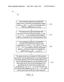
[0040] Please refer to FIG. 4, which is a schematic diagram of a decoding process 40 according to an embodiment of the present invention. The decoding process 40 is executed by the receiving device RX.sub.2, to differentiate and successfully decode the data signals d.sub.A and d.sub.B as the decoded signals {circumflex over (d)}.sub.A and {circumflex over (d)}.sub.B. The decoding process 40 comprises following steps:
[0041] Step 400: The multilevel detection unit MLDT2 determines a plurality of hypothetical signal levels s.sub.AB,2(0), . . . , s.sub.AB,2(Q-1) according to the channel coefficients h.sub.A and h.sub.B.
[0042] Step 402: The elementary signal estimator ESE generates the pre-processed signal z.sub.AB and z.sub.2k, k=1, . . . , K, according to the received signal r.sub.2 received by the receiving device RX.sub.2.
[0043] Step 404: The multilevel detection unit MLDT2 calculates the preliminary symbol-level probability p.sub.q'=Pr{s.sub.AB,2=s.sub.AB,2(q)|z.sub.AB}, for q=0, . . . , Q-1, according to the pre-processed signal z.sub.AB and the plurality of hypothetical signal levels s.sub.AB,2(0), . . . , s.sub.AB,2(Q-1).
[0044] Step 406: The multilevel detection unit MLDT2 derives the log-likelihood ratio e.sub.ESE,A and the log-likelihood ratio e.sub.ESE,B for the user A and the user B respectively according to the preliminary symbol-level probability p.sub.q', for q=0, . . . , Q-1.
[0045] Step 408: The decoding unit DU.sub.A generates the decoded signal {circumflex over (d)}.sub.A corresponding to the data signal d.sub.A of the transmitting device TX.sub.2A together with the decoded soft output e.sub.DEC,A which will be sent back to the ESE to generate e.sub.ESE,A for the next iteration. The decoding unit DU.sub.B generates the decoded signal {circumflex over (d)}.sub.B corresponding to the data signal d.sub.B of the transmitting device TX.sub.2B together with the decoded soft output e.sub.DEC,B which will be sent back to the ESE to generate e.sub.ESE,B for the next iteration.
[0046] In Step 400, the multilevel detection unit MLDT2 utilizes TABLE II to determine plurality of hypothetical signal levels s.sub.AB,2(0), . . . , s.sub.AB,2(Q-1). Again, the multilevel detection unit MLDT2 hypothesizes that the hypothetical signal level s.sub.AB,2(0) is h.sub.A+h.sub.B under an occasion that the interleaved signal x.sub.2A of the user A is 0 and the interleaved signal x.sub.2B of the user B is 0, hypothesizes that the hypothetical signal level s.sub.AB,2(1) is h.sub.A-h.sub.B under an occasion that the interleaved signal x.sub.2A of the user A is 0 and the interleaved signal x.sub.2B of the user B is 1, hypothesizes that the hypothetical signal level s.sub.AB,2(2) is -h.sub.A+h.sub.B under an occasion that the interleaved signal x.sub.2A of the user A is 1 and the interleaved signal x.sub.2B of the user B is 0, and hypothesizes that the hypothetical signal level s.sub.AB,2(3) is -h.sub.A-h.sub.B under an occasion that the interleaved signal x.sub.2A of the user A is 1 and the interleaved signal x.sub.2B of the user B is 1. In addition, the hypothetical transmitted signal y.sub.h,2A(y.sub.h,2B) being +1 means that the transmitted signal y.sub.2A (y.sub.2B) is hypothesized to be +1, and the hypothetical transmitted signal y.sub.h,2A (y.sub.h,2B) being -1 means that the transmitted signal y.sub.2A (y.sub.2B) is hypothesized to be -1.
TABLE-US-00002 TABLE II Occasion y.sub.2A/ y.sub.2B/ index q x.sub.2A x.sub.2B y.sub.h, 2A y.sub.h, 2B s.sub.AB, 2 (q) 0 0 0 +1 +1 h.sub.A + h.sub.B 1 0 1 +1 -1 h.sub.A - h.sub.B 2 1 0 -1 +1 -h.sub.A + h.sub.B 3 1 1 -1 -1 -h.sub.A - h.sub.B
[0047] In Step 402, the elementary signal estimator ESE generates the pre-processed signal z.sub.AB according to the received signal r.sub.2 received by the receiving device RX.sub.2. We may express E(.zeta..sub.AB) as E(.zeta..sub.AB)=E(r.sub.2)-h.sub.AE(y.sub.2A)-h.sub.BE (y.sub.2B)=.SIGMA..sub.k=1.sup.Kh.sub.2kE(y.sub.2k), where E(y.sub.2k) is set to zero in the first iteration and set to tan h(e.sub.DEE(x.sub.2k)/2) in the following iterations which can be obtained from the soft output of DU.sub.k.
[0048] In Step 404, the preliminary symbol-level probability p.sub.q'=Pr{s.sub.AB,2=s.sub.AB,2(q)|z.sub.AB}, q=0, . . . , Q-1 is calculated by p.sub.q'=Pr{z.sub.AB|s.sub.AB,2=s.sub.AB,2(q)}Pr{s.sub.AB,2=s.sub.AB,2(q)- }/Pr{z.sub.AB}. By assuming that s.sub.AB,2(0), . . . , s.sub.AB,2(Q-1) are equally likely, the term Pr{s.sub.AB,2=s.sub.AB,2(q)}/Pr{z.sub.AB} may be modeled as a constant C. Hence, p.sub.q' may be calculated by p.sub.q'=CPr{z.sub.AB|s.sub.AB,2=s.sub.AB,2(q)}, where
Pr { z AB | s AB , 2 = s AB , 2 ( q ) } = 1 2 .pi.Var { .zeta. AB } exp ( - z AB - s AB , 2 ( q ) 2 2 Var { .zeta. AB } ) , ##EQU00014##
wherein Var{.zeta..sub.AB}=.SIGMA..sub.k=1.sup.K<|h.sub.2k|.sup.2Var(y- .sub.2k)+.sigma..sup.2 and Var(y.sub.2k)=1-E(y.sub.2k).sup.2.
[0049] In Step 406, the multilevel detection unit MLDT2 calculates the log-likelihood ratio e.sub.ESE,A as e.sub.ESE,A=ln [Pr{x.sub.2A=0|z.sub.AB}/Pr{x.sub.2A=1|z.sub.AB}]=[p.sub.0'+p.sub.1']/[p.- sub.2'+p.sub.3'] and the log-likelihood ratio e.sub.ESE,B as e.sub.ESE,B=ln [Pr{x.sub.2B=0|z.sub.AB}/Pr{x.sub.2B=1|z.sub.AB}]=[p.sub.0'+p.sub.2']/[p.- sub.1'+p.sub.3]. Note that, Pr{x.sub.2A=0|z.sub.AB}, Pr{x.sub.2A=1|z.sub.AB}, Pr{x.sub.2B=0|z.sub.AB}, and Pr{x.sub.2A=1|z.sub.AB} are bit-level probabilities, and p.sub.0', . . . , p.sub.3' are symbol-level probabilities. The ESE may also calculate e.sub.ESE,k, k=1, . . . , K.
[0050] Note that, in Steps 402 to 408, the iterative decoding for user 1, . . . , K and user A and user B are processed in a parallel manner, and not limited herein. The iterative decoding may be processed in a serial manner by which the soft output of some of DU.sub.1, . . . , DU.sub.K and DU.sub.A and DU.sub.B already generated within a certain iteration can be used for other users in the same iteration.
[0051] According to the detection/decoding process 40, the receiving device RX.sub.2 in the multiple access communication system 30 is able to differentiate and successfully decode the data signals from different transmitting device/users, which utilize the same interleaver to generate their transmitted signals.
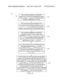
[0052] The system 30 and detection/decoding process 40 can be modified to a multiple access communication system 50 and a detection/decoding process 60. Please refer to FIG. 5 and FIG. 6, which are schematic diagrams of the multiple access communication system 50 and the detection/decoding process 60, respectively, according to an embodiment of the present invention. The decoding process 60 is executed by a receiving device RX.sub.3 within the multiple access communication system 50, to differentiate and successfully decode the data signals d.sub.A and d.sub.B as the decoded signals {circumflex over (d)}.sub.A and {circumflex over (d)}.sub.B, where the receiving device RX.sub.3 comprises a multilevel detection unit MLDT3. The detection/decoding process 60 as shown in FIG. 6 comprises following steps:
[0053] Step 600: The multilevel detection unit MLDT3 determines a plurality of hypothetical signal levels s.sub.AB,2(0), . . . , s.sub.AB,2(Q-1) according to the channel coefficients h.sub.A and h.sub.B.
[0054] Step 602: The elementary signal estimator ESE generates the pre-processed signal z.sub.AB and z.sub.2k, k=1, . . . , K, according to the received signal r.sub.2 received by the receiving device RX.sub.3.
[0055] Step 604: The multilevel detection unit MLDT3 calculates the preliminary symbol-level probability p.sub.q'=Pr{S.sub.AB,2=S.sub.AB,2(q)|z.sub.AB}, for q=0, . . . , Q-1, according to the pre-processed signal z.sub.AB and the plurality of hypothetical signal levels s.sub.AB,2(0), . . . , s.sub.AB,2(Q-1).
[0056] Step 606: The generalized sum-product (G-SPA) decoder generates the decoded signal {circumflex over (d)}.sub.A corresponding to the data signal d.sub.A of the transmitting device TX.sub.2A and the decoded signal {circumflex over (d)}.sub.B corresponding to the data signal d.sub.B of the transmitting device TX.sub.2B according to the preliminary symbol-level probability p.sub.q' for q=0, . . . , Q-1 from the ESE and also generated updated p.sub.q' for q=0, . . . , Q-1, which will be sent back to ESE for a later iteration.
[0057] The generalized sum-product (G-SPA) decoder is known by those skilled in the art. Readers may be referred to D. Wubben and Y. Lang, "Generalized sum-product algorithm for joint channel decoding and physical-layer network coding in two-way relay systems," Global Telecommunication Conference (GLOBECOM 2010), December 2010, which is not narrated herein for brevity. Other details of the detection/decoding process 60 is similar to the detection/decoding process 60, which is not narrated herein as well.
[0058] Notably, the embodiments stated in the above are utilized for illustrating the concept of the present invention. Those skilled in the art may make modifications and alternations accordingly, and not limited herein. For example, in the multiple access communication systems 10 and 30, a number of users/transmitting devices using the same signature (either spreading code or interleaver) is two, which is not limited. The multiple access communication systems may accommodate more than two users/transmitting devices which use one single signature to generate their transmitted signals. Moreover, suppose that the multiple access communication system of the present invention owns N distinct signatures, and each signature is shared by M users/transmitting devices. Therefore, a total number of users/transmitting devices accommodated in the multiple access communication systems is N*M.
[0059] Please refer to FIG. 7 and FIG. 8, which illustrate performance curves of bit error rate (BER) over the block Rayleigh fading channels for the multiple access communication systems of the present invention. In FIG. 7, the multiple access communication system is the CDMA system with 16 distinct spreading codes (i.e., the code length SP=16). Scenario I represents that there are 16 users in the CDMA system and each user occupies one spreading code, which is equivalent to the conventional CDMA system. Scenario II represents that there are 17 users in the CDMA system and 2 of the 17 users share one spreading code. Scenario III represents that there are 32 users in the CDMA system and each spreading code (of the 16 distinct spreading codes) is shared by 2 users. Scenario IV represents that there are 18 users in the CDMA system and 3 of the 18 users share one spreading code. Scenario V represents that there are 48 users in the CDMA system and each spreading code is shared by 3 users. In FIG. 8, the multiple access communication system is the IDMA system with 16 distinct interleavers. Scenario VI represents that there are 16 users in the IDMA system and each user occupies one interleaver, which is equivalent to the conventional IDMA system. Scenarios VII and IX represent that there are 17 users in the IDMA system and 2 of the 17 users utilize a same interleaver. Scenarios VIII and X represent that there are 18 users in the IDMA system and 4 of the 18 users utilize 2 shared interleavers (each shared interleaver is utilized by 2 users). Scenario XI represents that there are 19 users in the IDMA system and 6 of the 19 users utilize 3 shared interleavers (each shared interleaver is utilized by 2 users). Note that, in scenarios VII and VIII, the receiving device does not use the decoding process of the present invention to differentiate and decode signals. In scenarios II, III, IV, V, IX, X and XI, the receiving device does use the decoding process of the present invention to differentiate and decode signals. As can be seen from FIG. 7 and FIG. 8, the BER performance of the receiving device using the decoding process of the present invention is comparable with conventional CDMA/IDMA receiver, given that the total number of users is significantly increased. In addition, as the receiving device does not use the decoding process of the present invention, the BER performance is seriously degraded.
[0060] In summary, when the receiving device utilizes the decoding process of the present invention, the data signals of multiple users/transmitting device is able to be differentiated and successfully detected/decoded. Compared to the prior art, the multiple access system may accommodate more users, and the user capacity of the multiple access system is enhanced.
[0061] Those skilled in the art will readily observe that numerous modifications and alterations of the device and method may be made while retaining the teachings of the invention. Accordingly, the above disclosure should be construed as limited only by the metes and bounds of the appended claims.
User Contributions:
Comment about this patent or add new information about this topic:
Images included with this patent application:
 |  |
 |  |
 |  |
 |  |
 |  |
| New patent applications in this class: | |
| Date | Title |
|---|---|
| 2022-09-22 | Electronic device |
| 2022-09-22 | Front-facing proximity detection using capacitive sensor |
| 2022-09-22 | Touch-control panel and touch-control display apparatus |
| 2022-09-22 | Sensing circuit with signal compensation |
| 2022-09-22 | Reduced-size interfaces for managing alerts |