Patent application title: Method and System for Pouring Consecutive Separating Sections of Concrete Structures
Inventors:
IPC8 Class: AE04G1106FI
USPC Class:
1 1
Class name:
Publication date: 2017-03-23
Patent application number: 20170081866
Abstract:
A device and method tor pouring consecutive concrete sections. The
inventive device and method preferably include a barrier used to separate
adjacent concrete slabs. This barrier is preferably erected in such a way
that it allows a construction crew to continuously pour concrete in
successive sections of a concrete structure, which prior to the current
invention, could not be poured continuously. Previously, concrete
sections were poured in an alternating fashion in order to create an
expansion joint between each section of concrete which also acts to break
the bond between each concrete section. However, the current inventive
method and device allows the crew to pour adjacent concrete sections
while still creating a joint between each concrete section. Each concrete
section barrier preferably includes an upright surface and a keyway which
acts to create a mortis and tenon joint.Claims:
1. A method for pouring consecutive concrete sections using concrete
comprising the steps of: a. providing at least three concrete section
barriers, each of said at least three concrete section barriers having:
i. a surface, ii. a length, iii. a keyway having a mortise and a tenon;
b. providing at least two form walls: c. fixing said at least two form
walls in a position to form a channel; d. inserting said at least three
concrete section barriers such that said at least three concrete section
barriers are capable of separating said channel into at least two gaps;
e. maintaining said at least three concrete section barriers in an
upright position; and f. pouring said concrete in said at least two gaps
consecutively and continuously.
2. The method of claim 1, further comprising the step of allowing said concrete to adhere to said keyway at said mortise and said tenon, thereby creating a mortise and tenon joint after said concrete sets.
3. The method of claim 1, wherein said at least three concrete section barriers are comprised of molded plastic.
4. The method of claim 1, wherein said at least three concrete section barriers are comprised of ceramic.
5. The method of claim 1, wherein said at least three concrete section barriers are comprised of a composite material.
6. The method of claim 1, wherein said at least three concrete section harriers are comprised of coated steel or any other rigid material.
7. The method of claim 1, wherein said step of fixing said at least two form walls further comprises positioning said at least two form walls such that said at least two form walls conform to said length of said at least three concrete section barriers.
8. The method of claim 1, wherein said at least three concrete section barriers each include at least one dowel sleeve.
9. The method of claim 8, further comprising the step of: a. providing at least one dowel, and b. inserting said at least one dowel into said at least one dowel sleeve.
10. The method of claim 9, wherein said at least one dowel sleeve is an extruded cylinder and includes a dowel sleeve opening.
11. The method of claim 10, further comprising allowing said concrete to adhere to said at least one dowel in a first gap and said at least one dowel sleeve in a second gap, such that said concrete in said first gap and said concrete in said second gap are not fixed together.
12. The method of claim 11, wherein said at least one dowel is capable of translating within said at least one dowel sleeve upon said concrete expanding.
13. The method of claim 11, wherein said at least one dowel is capable of translating within said at least one dowel sleeve upon said concrete contracting.
14. A method for pouring consecutive concrete sections using concrete comprising the steps of: a. providing at least three concrete section barriers, each of said at least three concrete section barriers having: i. a surface, ii. a length, iii. a keyway having a mortise and a tenon; b. providing at least two form walls; c. arranging said at least two form walls and said at least three concrete section barriers such that said at least two form walls form a channel that said at least three concrete section barriers separate into at least two gaps; d. maintaining said at least three concrete section barriers in an upright position; and e. pouring said concrete in said at least two gaps consecutively and continuously.
15. The method of claim 14, further comprising the step of allowing said concrete to adhere to said keyway at said mortise and said tenon, thereby creating a mortise and tenon joint after said concrete sets.
16. The method of claim 14, wherein said at least three concrete section barriers are comprised of molded plastic.
17. The method of claim 14, wherein said at least two form walls conform to said length of said at least three concrete section barriers.
18. The method of claim 14, wherein said step of maintaining said at least three concrete section barriers includes attaching said at least three concrete section barriers to said at least two form walls using at least three chamfer strips.
19. A method for pouring consecutive concrete slabs using concrete comprising: a. providing at least three concrete section barriers, each having: i. a surface, ii. a length, iii. a keyway having a mortise and a tenon; b. providing at least two form walls; c. arranging said at least two form walls and said at least three concrete section barriers to create at least two gaps; d. maintaining said at least three concrete section barriers in an upright position; and e. pouring said concrete in said at least two gaps prior to allowing said concrete to set.
20. The method of claim 19, wherein said step of maintaining said plurality of concrete section barriers in an upright position further comprises providing a plurality of chamfers attached to said plurality of concrete section barriers and said at least two form walls.
Description:
CROSS-REFERENCES TO RELATED APPLICATIONS
[0001] This non-provisional patent application is a continuation-in-part of U.S. application Ser. No. 14/471,826, filed on Aug. 28, 2014, which is a continuation-in-part of U.S. application Ser. No. 14/016,412, filed on Sep. 3, 2013, which is a continuation-in-part of U.S. application Ser. No. 13/787,487. The original application was filed on Mar. 6, 2813. All applications list the same inventors.
STATEMENT REGARDING FEDERALLY SPONSORED RESEARCH OR DEVELOPMENT
[0002] Not applicable
MICROFICHE APPENDIX
[0003] Not Applicable
BACKGROUND OF THE INVENTION
[0004] 1. Field of the Invention
[0005] This invention relates to the field of roadway construction. More specifically, the present invention comprises a device and method for separating sections of concrete for multiple structures,
[0006] 2. Description of the Related Art
[0007] Governing bodies, such as the department of transportation for states and other territories, have rules and regulations which must be followed when erecting structures associated with walking paths and roadways. These restrictions pertain to roads, sidewalks, retaining, gravity and barrier walls, junction and/or moment slabs and other structures that are constructed using concrete. Although these restrictions are enforced with public safety and structural integrity in mind, the regulations create inefficiencies during construction.
[0008] One of the main restrictions mandated by many governing bodies for construction of retaining walls, gravity walls, barrier walls, and junction slabs is that each structure must have concrete poured in separate sections of a specified length. The separate sections of concrete create joints along the length of the structure. These joints allow for expansion, contraction, bond breaks, and movement of each individual section of concrete, thereby decreasing the likelihood of cracking and other complications. In addition, some structures require an interlocking joint comprising a mortise and tenon, wherein each concrete section is not bonded together.
[0009] In the case of a junction or moment slab, this expansion joint (also known as a "bond break" joint) is created using an alternating pouring method. This method begins with measuring and creating a section, which may include a mortise and tenon. One section is poured, then the next section is skipped, then one is poured and so on. This creates alternately poured sections. Once those sections are dry, the empty sections are filled. The goal is to keep the separate sections of concrete from bonding together. A similar method is used for a gravity and retaining wall which is described further below.
[0010] In the case of gravity or retaining wall, the expansion joint (also known as the "bond break" joint) is typically created by pouring alternating sections of concrete as well. The current process used to create an array of gravity or retaining walls requires the construction team to measure out each section of concrete to be poured. However, due to the requirement of an expansion joint, whereby each section must not be bonded together, the sections are poured in an alternating fashion. Typically, a first section is poured, then a space which is equal to the length of a section is left vacant. Next, concrete is poured adjacent to the open space for a section, and so on down the line of gravity or retaining walls.
[0011] Once the first sections of concrete slabs have dried and cured, the pieces of lumber are removed from the dried concrete, creating a mortise. Next, workers line the dried concrete sections with expansion paper. Then, the vacant sections can be filled with concrete (this is typically done the day after the first concrete sections are poured). Thus, the adjacent concrete sections are prevented from bonding together, and the required expansion joint is formed between each section of concrete. In addition, dowel bars may be inserted at regular intervals along the length of each piece of lumber. The hole for each dowel bar must be measured and drilled prior to pouring concrete.
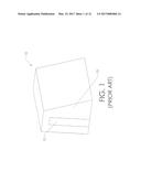
[0012] FIG. 1 shows a single section of concrete. Concrete section 10 was formed using form walls (not shown) on each side of the concrete section to be poured. Oftentimes, a keyway is required such that adjacent concrete sections interlock. Typically, a lumber plank 12 is used to create this keyway. This is achieved by attaching lumber plank 12 to the form wall used to create front surface 13. This is done before concrete can be poured. FIG. 1 shows a singular section once ail the form walls have been pulled away. In many instances lumber plank 12 is nailed to the form wall used to create front surface 13. Once the concrete has dried, lumber plank 12 is removed from the dried concrete section 10. Typically, lumber plank 12 is firmly stuck within concrete section 10. Therefore, workers must chip away at the wooden plank 12 in order to remove it. This can be time consuming and tiresome, thereby extending the duration of the job.
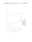
[0013] The concrete section 10 with lumber plank 12 removed is shown in FIG. 2. Due to the dried concrete and the removal of lumber plank 12, mortise 14 is created in concrete section 10. Prior to pouring the adjacent section of concrete, felt paper must be placed everywhere on concrete section 10 which will be in contact with the section to be poured-this creates a bond break between the two sections of concrete. This includes front surface 13 and mortise 14. Now, concrete can be poured adjacent to concrete section 10 in order to form a wall with interlocking joints. Unfortunately, the crew must wait (typically a full day) to pour the adjacent section of concrete.
[0014] Therefore, what is needed is a device and method which allows a construction team to continuously pour isolated sections of concrete during the fabrication of an array of gravity or retaining walls. The present method achieves this objective, as well as others that are explained in the following description.
BRIEF DESCRIPTION OF THE INVENTION
[0015] The present invention comprises a method for pouring consecutive concrete sections which are disjoint. The present invention includes the required bond breaks, which prevent the adjacent concrete slabs from bonding to each other. This joint is referred to throughout the following disclosure as an expansion joint or bond breaking joint, as it serves a dual purpose. The inventive method preferably includes a barrier used to separate adjacent concrete slabs. This barrier is preferably erected in such a way that it allows a construction crew to continuously pour concrete in successive sections of a concrete structure, which prior to the current invention, could not be poured continuously. Previously, concrete sections were poured in an alternating fashion in order to create an expansion joint between each section of concrete. However, the current inventive method and device allow the crew to pour adjacent concrete sections while still creating an expansion joint between each concrete section and preventing the two sections to bond together.
[0016] Each concrete section barrier preferably includes an upright surface and keyway. Prior to pouring concrete into each designated gap, which have been measured and sectioned off, each section barrier is erected between each section of concrete to be poured. In some instances, the concrete section barrier includes sleeves in which dowel bars can be inserted. Then, each sectioned off space is filled with concrete in a manner that allows a crew to pour adjacent sections consecutively. This is an improvement on the previous method, wherein alternating gaps are filled on a first day, and then the remaining gaps are filled on a second day.
BRIEF DESCRIPTION OF THE SEVERAL VIEWS OF THE DRAWINGS
[0017] FIG. 1 is a perspective view, showing a prior art method of creating concrete sections.
[0018] FIG. 2 is a perspective view, showing a prior art concrete section with the lumber plank removed.
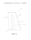
[0019] FIG. 3 is a perspective view, showing a preferred embodiment of the concrete section barrier of the present invention.
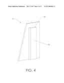
[0020] FIG. 4 is a perspective view, showing a preferred embodiment of the concrete section barrier of the present invention.
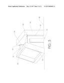
[0021] FIG. 5 is a perspective view, showing the concrete section barrier of FIG. 3 between two form walls.
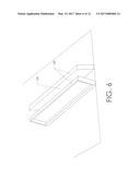
[0022] FIG. 6 is a perspective view, showing the channel created by two form walls.
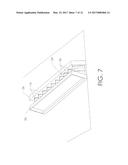
[0023] FIG. 7 is a perspective view, showing multiple concrete section barriers inserted between form walls.
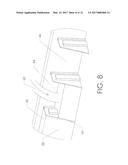
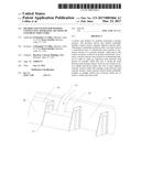
[0024] FIG. 8 is a perspective view, showing the present inventive method of pouring concrete sections.
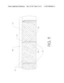
[0025] FIG. 9 is a sectional view, showing the poured concrete sections with concrete section barriers separating each section of concrete.
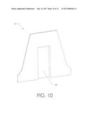
[0026] FIG. 10 is a perspective view, showing another embodiment of the concrete section barrier of the present invention.
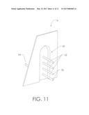
[0027] FIG. 11 is a perspective view, showing concrete section barrier including dowel sleeves.
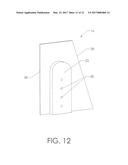
[0028] FIG. 12 is a perspective view, showing concrete section barrier including dowel sleeve openings.
REFERENCE NUMERALS IN THE DRAWINGS
[0029] 10 concrete section
[0030] 12 lumber plank
[0031] 13 front surface
[0032] 14 mortise
[0033] 16 concrete section barrier
[0034] 18 surface
[0035] 20 keyway
[0036] 22 concave surface
[0037] 24 convex surface
[0038] 26 form wall
[0039] 28 ground
[0040] 30 chamfer strip
[0041] 32 form wall
[0042] 34 channel
[0043] 36 gap
[0044] 38 first gap
[0045] 40 first concrete section
[0046] 42 wet concrete
[0047] 44 second gap
[0048] 46 third gap
[0049] 48 concrete wall
[0050] 50 tenon
[0051] 52 dowel sleeve
[0052] 54 dowel bar
[0053] 56 closed end of dowel sleeve
[0054] 58 length
[0055] 60 dowel sleeve opening
DETAILED DESCRIPTION OF THE INVENTION
[0056] The present Invention provides a method and device for separating sections of concrete during construction of structures on or near a roadway. A preferred embodiment of the present concrete section barrier 16 is shown in FIG. 3. Preferably, concrete section barrier 16 includes surface 18 and keyway 20. As illustrated, key way 20 creates a concave surface 22 on surface 18. FIG. 3 shows the front side of concrete section barrier 16 while FIG. 4 shows the back side of concrete section barrier 16. In FIG. 4, the convex surface 24 of keyway 20 is visible on surface 18. As will be discussed in the following text, keyway 20 creates interlocking sections of concrete 10 while allowing the construction team to continuously pour concrete in adjacent sections as opposed to pouring alternating sections which is the current method of creating Interlocking concrete walls. Concave surface 22 of keyway 20 is a mortise 14, while convex surface 24 of keyway 20 is a tenon 50. Mortise 14 and tenon 50 create interlocking sections of concrete 10.
[0057] In one embodiment of the present invention, concrete section barrier 16 is fabricated using a molded plastic. A molded plastic material is capable of expansion and contraction. In addition, corrosion of molded plastic is less likely than with a metallic material such as steel or aluminum. However, it should be noted that molded plastic may be the preferred embodiment, there may be other suitable materials used for concrete section barrier 16. Some examples of suitable materials for barrier 16 are composites, ceramics, different types of coated steels/other metals, or other plastic materials.
[0058] FIG. 5 shows concrete section barrier 16 in use. The reader will note that the figure only shows a single concrete section to be poured. Form walls 26 and concrete section barriers 16 are arranged on the ground 28 in the location the user intends to place the gravity or barrier wall, Concrete section barriers 16 are positioned at a specified distance apart between form walls 26. The distance between each barrier 16 will be the length of the concrete section to be poured. Therefore, the desired distance between each barrier 16 is carefully calculated and measured. This insures each concrete section conforms to the standards required by the local governing body in that area. In order to maintain the position of concrete section barrier 16 during the pouring of concrete, chamfer strips 30 are used to attach barrier 16 to form wall 26. Preferably, chamfer strips 30 are located at every form wall--barrier junction 32. The reader will note that there are four form wall--barrier junctions 32 for each concrete section barrier 16.
[0059] Prior to pouring concrete in order to fabricate a barrier or gravity wall according to the present invention, form walls 26 and concrete section barriers 16 must be erected. This is show in FIGS. 6 and 7. As illustrated, the preferred placement of form, walls 26 creates channel 34. Concrete section barriers 16 can optionally be used to facilitate the proper arrangement of form walls 26. Form walls 26 are properly positioned when form walls 26 conform to length 58 of concrete section barriers 16 on either side, as shown in FIG. 5. FIG. 7 shows multiple concrete section barriers 16 in an array placed within channel 34 in order to form a gravity or retaining wall. It is important that concrete section barriers 16 are correctly positioned. As discussed in the previous text, each barrier 16 is positioned at a predetermined distance from the previous barrier 16. This placement of barriers 16 creates multiple gaps 36 within channel 34, which are a specified distance apart. After the concrete section barriers 16 are in position, the crew is ready to pour the concrete. The reader will note that in the figure a single form wall 26 is used to span the length of channel 34 on either side. Depending on the length of the concrete wall to be built and the available materials, this may be broken up into many form walls 26 along the concrete wall.
[0060] The reader will note that one of the form walls 26 have been removed from the view in FIG. 8 in order to clearly show the pouring of the concrete sections. As discussed in the previous text, the present inventive device and method allows a user to construct a concrete barrier using a continuous pour of concrete instead of pouring alternating sections of concrete, waiting for those sections to dry, and then coming back to pour the remaining sections. FIG. 8 shows a concrete wall, being constructed in such a manner. As illustrated, first gap 38 is filled with concrete in order to create first concrete section 40. Of course, first concrete second 40 is still wet as the concrete was poured moments before concrete is poured into second gap 44 (illustrated in FIG. 8). At this instant, wet concrete 42 is being poured into second gap 44. The reader will note that first gap 38 and second gap 44 are adjacent to one another, having only concrete section barrier 16 separating them. Once second gap 44 is filled with concrete 42, concrete 42 is poured into third gap 46. This continues down the line until each gap 36 is filled.
[0061] Creating a gravity or barrier wall using the current inventive method saves a great deal of time and cost. Concrete section barrier 16 allows for a continuous pour, which eliminates the need pour alternating sections, allow those sections to dry, and then come back the next day to pour the remaining sections. A continuous pour (or pouring continuously), for purposes of the present method, means pouring at least two consecutive sections before the wet concrete is able to dry. In addition, concrete section barrier 16 preferably creates a keyway between adjacent walls without the need to use a wooden plank. This saves a great deal of time because workers do not need to chip away at wooden planks embedded into concrete in order to create the required mortise and tenon joint.
[0062] FIG. 9 shows a sectional view of concrete wall 48, such as a barrier or gravity wall. As shown, each concrete section 10 is separated by concrete section barrier 16. This separation preferably creates a bond break between each section of concrete 10 as well as an expansion joint which allows the concrete to expand and contract as necessary. In addition, concrete section barrier creates a mortise 14 and tenon 50 between each section. This is preferably achieved using key way 20 as opposed to lumber plank 12.
[0063] FIG. 10 shows another embodiment of concrete section barrier 16. The reader will note that the shape of barrier 16 in FIG. 10 is different than that shown in FIG. 3. However, barrier 16 (in FIG. 10) also includes keyway 20 in order to create a mortise and tenon joint. The embodiment, shown in FIG. 10 is typically used in conjunction with a barrier wall, whereas the embodiment of FIG. 3 is typically used for a gravity wall. While the two barriers 16 have different shapes, those familiar with the art will realize that both embodiments perform the task in the same manner.
[0064] FIG. 11 shows another embodiment of concrete section barrier 16. This particular embodiment preferably includes upright surface 18, keyway 20, and dowel sleeves 52. In the case where the concrete wall to be built requires reinforcement dowels, concrete section barrier 16 may include dowel sleeves 52. Preferably, dowel sleeves 52 penetrate surface 18 of concrete section barrier 16, and are hollow, cylindrical conduits with a closed end. A dowel bar 54 can be inserted into the open end of dowel sleeve 52. Preferably, dowel sleeve 52 includes closed end 56 so that the bond breaking and expansion features of barrier 16 is maintained. Using this method, dowel bar 54 is capable of axially translating within dowel sleeve 52, allowing for expansion and contraction of the two concrete sections on either side of section barrier 16.
[0065] FIG. 12 shows the opposite side of concrete section barrier 16 to that shown in FIG. 11. In this view, dowel sleeve openings 60 are visible. Dowel sleeve openings 60 preferably allow a user to insert dowel bars 54 (not shown in this drawing view) into dowel sleeve 52 (shown in FIG. 11). As illustrated, dowel sleeve openings 60 are preferably located on concave surface 22. However, sleeve openings 60 may also be located on the convex surface of the keyway 20.
[0066] The preceding description contains significant detail regarding the novel aspects of the present invention. It should not be construed, however, as limiting the scope of the invention but rather as providing illustrations of the preferred embodiments of the invention. Thus, the scope of the invention should be fixed by the following claims, rather than by the examples given.
User Contributions:
Comment about this patent or add new information about this topic:
Images included with this patent application:
 |  |
 |  |
 |  |
 |  |
 |  |
 |  |
 |
| New patent applications in this class: | |
| Date | Title |
|---|---|
| 2022-09-22 | Electronic device |
| 2022-09-22 | Front-facing proximity detection using capacitive sensor |
| 2022-09-22 | Touch-control panel and touch-control display apparatus |
| 2022-09-22 | Sensing circuit with signal compensation |
| 2022-09-22 | Reduced-size interfaces for managing alerts |