Patent application title: METHOD FOR DETERMINING THE CONDUCTIVITY OF A MEDIUM
Inventors:
IPC8 Class: AG01R3500FI
USPC Class:
1 1
Class name:
Publication date: 2017-02-23
Patent application number: 20170052243
Abstract:
The present disclosure relates to a method for determining the
conductivity of a medium by means of a conductive conductivity sensor,
comprising the steps of determining measured values of the conductivity
sensor, determining reference measured values of a reference circuit
integrated into the conductivity sensor, deriving at least one adjustment
value from the reference measured values of the reference circuit, and
correcting the measured values of the conductivity sensor by means of the
at least one adjustment value.Claims:
1. A method for determining the conductivity of a medium by means of a
conductive conductivity sensor, comprising the steps: determining
measured values of the conductivity sensor; determining reference
measured values of a reference circuit integrated into the conductivity
sensor; deriving at least one adjustment value from the reference
measured values of the reference circuit; and correcting the measured
values of the conductivity sensor by means of the at least one adjustment
value.
2. The method according to claim 1, further comprising: alternating between determining the measured values of the conductivity sensor and determining the reference measured values of the reference circuit in a time-controlled manner.
3. The method according to claim 2, further comprising: determining two measured values of the conductivity sensor and subsequently determining one reference measured value of the reference circuit.
4. The method according to claim 1, wherein the conductivity sensor includes an electronic component with at least two measurement ranges including an active measuring range, and the method further comprises: during a measurement, adjusting the active measuring range more frequently than the other measurement ranges.
Description:
CROSS-REFERENCE TO RELATED APPLICATION
[0001] The present application is related to and claims the priority benefit of German Patent Application No. 10 2015 113 922.7, filed on Aug. 21, 2015, the entire contents of which are incorporated herein by reference.
TECHNICAL FIELD
[0002] The present disclosure relates to a method for determining the conductivity of a medium by means of a conductive conductivity sensor.
BACKGROUND
[0003] A conductivity sensor includes a measuring circuit for measuring the electrical conductivity of a medium based upon a resistance measurement of the medium and the subsequent calculation with a factor that is referred to as a cell constant and results from the geometry of the conductivity sensor. Typically, the measuring circuits for a conductivity sensor are adjusted during the production. In the process, errors, such as amplification and zero point errors, are determined, and correction values, if any, are stored in the non-volatile memory. Such an adjustment usually occurs at room temperature, since a change in the temperature is difficult to implement during the adjustment. Such a conductivity sensor is operated at the customer's premises for a time period of many years and is there exposed to various environmental conditions, such as humidity and temperature fluctuations.
[0004] The correction values for the measuring circuit are determined at a point in time when defined environmental conditions, such as temperature, prevail. As a result of molding of the measuring circuit from, for example, epoxy resin, temperature fluctuations, or aging over a long period of operation, deviations in the measuring chain of the measuring circuit can occur. These deviations may possibly impair the specified measurement precision of the conductivity sensor.
BRIEF SUMMARY OF THE INVENTION
[0005] The present disclosure includes a method for determining the conductivity of a medium by means of a conductive conductivity sensor with high measurement precision.
[0006] The object of the present disclosure is a method for determining the conductivity of a medium by means of a conductive conductivity sensor, comprising the steps of determining measured values of the conductivity sensor, determining reference measured values of a reference circuit integrated into the conductivity sensor, deriving at least one adjustment value from the reference measured values of the reference circuit, correcting the measured values of the conductivity sensor by means of the at least one adjustment value.
[0007] The solution according to the present disclosure is advantageous in that the reference circuit is integrated into the conductivity sensor (on-board adjustment) for automatic adjustment. With suitable algorithms and timed sequences, it is then possible to adjust the conductivity sensor during the measurement operation, to determine correction values and to always ensure an optimal measurement performance. Another advantage of the on-board adjustment is the diagnosis of malfunctions of certain circuit components. This may be realized by comparing the determined adjustment values with theoretical ideal values for the adjustment. If the determined correction values deviate too much from the theoretical values, a malfunction of the conductivity sensor exists, and the superordinate system may react accordingly.
[0008] According to at least one embodiment, a time-controlled alternation between the determination of the measured values of the conductivity sensor and the determination of the reference measured values of the reference circuit takes place. As a result of the cyclical adjustment of the conductivity sensor, medium-term changes of faulty components may be determined and adjusted. For example, the temperature influences on resistors and other components over time can be adjusted thereby.
[0009] According to an embodiment, two measured values of the conductivity sensor and, subsequently, one reference measured value of the reference circuit are determined.
[0010] According to another embodiment, the conductivity sensor comprises an electronic component with at least two measurement ranges, wherein, during a measurement, adjustments are made more frequently in an active measurement range than in the other measurement range(s).
[0011] Since the electronic component has several measurement ranges, it is expedient to adjust the currently active measurement range more frequently, in order to ensure the highest precision and best performance. If the other measurement ranges were, however, ignored, inaccuracies could occur over a longer period of time. This would, in particular, be the case if the temperature of the electronic component were to change while a measurement range is active. If the change to a different measurement range occurs at that time, the adjustment value would no longer be current in this range, and incorrect measured values would be determined. After a certain period of time, the error would be minimized, since the other measurement ranges are also adjusted.
BRIEF DESCRIPTION OF THE DRAWINGS
[0012] The described embodiments and other features, advantages and disclosures contained herein, and the manner of attaining them, will become apparent and the present disclosure will be better understood by reference to the following description of various exemplary embodiments of the present disclosure taken in conjunction with the accompanying drawings, wherein:
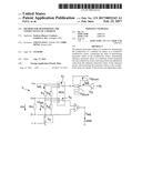
[0013] FIG. 1 shows a measuring circuit for measuring conductivity with an integrated reference circuit according to exemplary embodiments of the present disclosure.
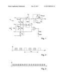
[0014] FIG. 2 depicts a sequence of medium and adjustment measurements according to exemplary embodiments of the present disclosure.
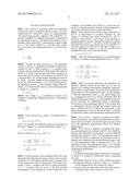
[0015] FIG. 3 depicts a sequence of medium and adjustment measurements in various measurement ranges according to exemplary embodiments of the present disclosure.
[0016] Like reference numerals indicate the same or similar parts throughout the several figures. It should be appreciated that not all of the features of the components of the figures are necessarily described. Some of these non-discussed features, such as various fasteners, etc., as well as discussed features are inherent from the figures. Other non-discussed features may be inherent in component geometry or configuration.
DETAILED DESCRIPTION
[0017] FIG. 1 shows a measuring circuit 3 for measuring conductivity with an integrated reference circuit. The measuring circuit 3 is operated by means of a signal generator (not shown) that provides a signal S.sub.f with a frequency f. A generator amplifier VG amplifies the signal S.sub.f and generates an adjustment current I.sub.adj. The adjustment current I.sub.adj flows through a shunt resistor R.sub.shunt and generates a shunt voltage U.sub.shunt. If the shunt voltage U.sub.shunt and the shunt resistor R.sub.shunt are known, the adjustment current I.sub.adj can be determined:
I adj . = U shunt R shunt ##EQU00001##
[0018] Through the shunt resistor R.sub.shunt, the adjustment current I.sub.adj flows to a multiplexer MUX that comprises two switches S.sub.1 and S.sub.2. Both switches S.sub.1, S.sub.2 comprise three positions and are synchronized, which means that if the top switch S.sub.1 is in the center position, the bottom switch S.sub.2 is also in the center position, etc. Connected to the MUX are voltage dividers, one voltage divider including the resistors R.sub.1 and R.sub.p1, the other voltage divider including the resistors R.sub.2 and R.sub.p2. If both switches S.sub.1, S.sub.2 are in the center position, the adjustment current I.sub.adj flows through voltage divider R.sub.1 and R.sub.p1 via a third closed switch S.sub.3 to ground and generates a voltage U.sub.Rpx along R.sub.p1:
U.sub.R.sub.px=R.sub.p1I.sub.adj.
[0019] The voltage U.sub.Rpx is amplified by means of an amplifier V, wherein the amplification factor v is determined as follows:
v = U adj . U R px ##EQU00002##
[0020] If the resistors R.sub.shunt and R.sub.p1 are dimensioned as follows:
R.sub.shunt=100 .OMEGA. R.sub.p1=390 .OMEGA.,
and if, for example, the following values are measured for the shunt voltage U.sub.shunt and the adjustment voltage U.sub.adj:
U.sub.shunt=100 MV U.sub.adj=2 V,
then the result for I.sub.adj, U.sub.Rpx, and v is:
I adj . = U shunt R shunt = 100 mV 100 .OMEGA. = 1 mA ##EQU00003## U R px = R p 1 I adj . = 390 .OMEGA. 1 mA = 390 mV ##EQU00003.2## v = 2 V 0.39 V = 5.128 _ ##EQU00003.3##
[0021] If both switches of the multiplexer MUX are in the top position, the adjustment current I.sub.adj flows via two current electrodes I+, I- through the medium, and a measured value of the conductivity sensor is determined. The current electrodes I+ and I-, together with the two voltage electrodes U+, U-, constitute the four poles of the four-terminal measurement of the conductivity sensor. During the measurement of the medium, the switch S.sub.3 is open and connected to a separate ground, so that the voltage electrode U- is not short-circuited with the current electrode I-.
[0022] If the medium between the voltage electrodes U+ and U- is represented by a medium resistance R.sub.m, the voltage U.sub.m between the voltage electrodes U+ and U- decreases. The current I.sub.m (not shown in the drawing) is regulated until the current I.sub.m through the medium is equal to the adjustment current I.sub.adj (see above). In this example, the following values were measured for the shunt voltage U.sub.shunt and the adjustment voltage U.sub.adj, after the switches were changed from the center to the top position:
U.sub.shunt=80 mV U.sub.adj=1 V
[0023] Thus, the medium resistance R.sub.m can be determined as follows, by means of the amplification factor v=5.128:
I m = U shunt R shunt = 80 mV 100 .OMEGA. = 0.8 mA ##EQU00004## U m = U adj . v = 1 V 5.128 = 195 mV ##EQU00004.2## R m = U m I m = 0.195 V 0.8 mA = 243.76 .OMEGA. _ ##EQU00004.3##
[0024] With an on-board adjustment, the conditions are, therefore, adjusted exactly in the same way as they are adjusted in a medium measurement (amplitude, frequency, shunt resistor, amplification). The goal of the adjustment is the calculation of the amplification factor v of the amplifier V. With the adjustment current I.sub.adj, the ideal voltage drop U.sub.Rpx through the resistor R.sub.p1 can be calculated. With the measured adjustment voltage U.sub.adj, the amplification factor v can be calculated. The amplification factor v compensates for all errors of the measuring circuit 3. If the current flow is subsequently directed through the medium again, the same conditions prevail as during the adjustment of the measurement range. However, the current flow is corrected or adjusted by means of the determined amplification factor v.
[0025] FIG. 2 shows a sequence of medium and adjustment measurements. The medium and adjustment measurements each last for half a second and occur once per second each. One adjustment measurement follows two medium measurements.
[0026] FIG. 3 shows a sequence of medium and adjustment measurements in accordance with FIG. 2, in which the medium and adjustment measurements occur in different measurement ranges 0, 1, and 2. The measurement range 0, in which the current conductivity measurement occurs, is adjusted more frequently than the measurement ranges 1 and 2. If the measurement range is changed from 0 to 1, the adjustment values for measurement range 1 are available and can be provided immediately, in order to ensure optimal measurement performance.
User Contributions:
Comment about this patent or add new information about this topic:
Images included with this patent application:
 |  |
 |  |
| New patent applications in this class: | |
| Date | Title |
|---|---|
| 2022-09-22 | Electronic device |
| 2022-09-22 | Front-facing proximity detection using capacitive sensor |
| 2022-09-22 | Touch-control panel and touch-control display apparatus |
| 2022-09-22 | Sensing circuit with signal compensation |
| 2022-09-22 | Reduced-size interfaces for managing alerts |