Patent application title: DEVICE AND METHOD FOR THE SURFACE MACHINING OF WORKPIECES
Inventors:
IPC8 Class: AB24B2900FI
USPC Class:
1 1
Class name:
Publication date: 2017-02-23
Patent application number: 20170050287
Abstract:
A device for surface machining of a workpiece includes: a plurality of
tools configured to rotate and/or oscillate around axes; and two tool
holders, arranged one behind the other in a direction of passing of the
workpiece. Each tool holder has at least one tool, the two tool holders
being movable in a common plane in opposite directions transverse to the
direction of passing of the workpiece. A maximum machining width of the
device corresponds to a sum of the widths of machining areas defined by
the tools transverse to the direction of passing of the workpiece.Claims:
1. A device for surface machining of a workpiece, the device comprising:
a plurality of tools configured to rotate and/or oscillate around axes;
and two tool holders (15, 16), arranged one behind the other in a
direction of passing (14) of the workpiece, each tool holder (15, 16)
having at least one tool (12, 13), the two tool holders (15, 16) being
movable in a common plane in opposite directions transverse to the
direction of passing (14) of the workpiece, and wherein a maximum
machining width of the device (1) corresponds to a sum of the widths of
machining areas defined by the tools (12, 13) transverse to the direction
of passing (14) of the workpiece.
2. The device according to claim 1, further comprising guides (22, 23) in which the two tool holders (15, 16) are movable at a common carrier (21), the distance of the common carrier (21) relative to a machining plane of the workpiece being adjustable.
3. The device according to claim 2, further comprising: a circulating belt (26) at which the two tool holders (15, 16) are arranged; and a drive (25) configured to drive the circulating belt (26).
4. The device according to claim 1, wherein each tool holder (15, 16) has a plurality of tools (12, 13) arranged in a row transverse to the direction of passing (14) of the workpiece.
5. The device according to claim 4, wherein the tools (12, 13) of a particular tool holder (15, 16) have a common drive (17, 18).
6. A method for surface machining of a workpiece using a device according to claim 1, the method comprising: carrying out the surface machining with tools in the two tool holders (15, 16); rotating and/or oscillating the tools around axes of the tools; arranging the two tool holders (15, 16), which are displaceable transverse to a direction of passing (14) of the workpiece, one behind the other in the direction of passing (14) of a workpiece, wherein the width of every machining area defined by the tools (12, 13) transverse to the direction of passing (14) of the workpiece amounts to one half of a maximum machining width of the device (1); and oscillating the two tool holders (15, 16) transverse to the direction of passing (14) of the workpiece during the surface machining.
7. The method according to claim 6, wherein the two tool holders (15, 16) oscillate synchronously in opposite directions.
8. The method according to claim 6, wherein the tools of the two tool holders rotate and/or oscillate about their respective axes in opposite directions.
9. The method according to claim 6, wherein when tools work at an offset transverse to a center plane in the direction of passing (14) of the workpiece, an offset of the two tool holders (15, 16) transverse to a center plane (34) of the two tool holders (15, 16) is changed when there is wear of inner ones of the tools.
10. The method according to claim 6, wherein the two tool holders (15, 16) are positioned one directly behind the other during the surface treatment.
Description:
BACKGROUND OF THE INVENTION
[0001] 1. Field of the Invention
[0002] The invention is directed to a device with tools for the surface machining of workpieces, which tools rotate and/or oscillate around axes, and to a method for surface machining, particularly with a device of this kind.
[0003] 2. Description of the Related Art
[0004] There are many known devices and methods for machining surfaces of workpieces, for example, for deburring, polishing, texturing, or the like. Generally, brushes of all types, cup brushes, contact brushes or polishing brushes are used as tools particularly with workpieces extending substantially in two dimensions. Further, the devices used in manufacturing technology generally have a plurality of tools which are mostly arranged in a row to machine a workpiece.
[0005] The known devices are usually adapted very specifically to their intended use and are accordingly suited only for determined tools and workpieces.
SUMMARY OF THE INVENTION
[0006] In view of the foregoing, it is an object of the invention to provide a device and a method for surface machining which offer a number of possibilities for use.
[0007] In accordance with one aspect of the invention, the above set of problems may be solved using a device having tools for the surface machining of workpieces, which tools rotate and/or oscillate around axes, in which two tool holders are arranged, one behind the other, in a direction of passing of a workpiece, wherein every tool holder has at least one tool, the tool holders are movable in a common plane in opposite directions transverse to the direction of passing of the workpiece, and the maximum machining width of the device corresponds to the sum of the widths of the machining areas defined by the tools transverse to the direction of passing.
[0008] The device according to this aspect of the invention has many advantages. By providing tool holders, it becomes possible to clamp a wide variety of tools for the surface machining of workpieces. Further, each tool holder preferably has its own drive for the at least one tool so that the tool can be driven at an optimal speed or frequency. Brush forces that occur can also be safely contained.
[0009] In technical respects relating to manufacture and process, advantages result from the fact that the tool holders are movable in opposite directions in a common plane transverse to the direction of passing of the workpiece, particularly in connection with the step by which the maximum machining width of the device corresponds to the sum of the widths of the machining areas defined by the tools transverse to the direction of passing, as will be explained more fully in the following.
[0010] Further, it can be provided in a constructively simple manner that the tool holders are movable in guides at a common carrier and that the distance of the carrier relative to a machining plane of the workpiece can be adjusted. Accordingly, there is no need for an elevational adjustment of the tools. Rather, the elevational adjustment of the tool holders and, therefore, an adaptation to the utilized tools and workpieces, is carried out jointly with the carrier.
[0011] It is conceivable to move the tool holders in opposite directions transverse to the direction of passing pneumatically by pistons, providing the common carrier allows the tool holders to be arranged on a circulating belt with a drive. This belt is preferably a toothed belt.
[0012] In a constructional elaboration it is further provided that every tool holder has a plurality of tools arranged in a row transverse to the direction of passing of the workpiece. The tools of a tool holder can preferably have a common drive.
[0013] The device according to an aspect of the invention allows a surface machining of a workpiece from below as well as from above and a simultaneous surface machining of opposite sides of the workpiece in case of a twofold arrangement of components.
[0014] In particular, the quality of the surface machining is also exceptionally high when it is further provided that the tool holders oscillate transverse to the direction of passing during the surface machining. Machining gaps on the surface are reliably prevented in this way.
[0015] It can further be provided that the tool holders oscillate synchronously in opposite directions, particularly when the tool holders are arranged at a circulating belt with a drive at a common carrier. Accordingly, the synchronism takes place automatically.
[0016] To utilize the full machining width of the device, the tool holders with the tools are arranged one behind the other so as to be offset in direction of passing relative to a center plane. Since the inner tools generally wear faster than those located on the outside, it is provided, in case of tools working at an offset transverse to the center plane, to change the offset of the tool holders when the inner tools wear. A uniform wear of the tools is ensured in this way.
[0017] It is further provided that the axes of the tools of the two tool holders are arranged to provide for rotation and/or oscillation in opposite directions. This is advantageous particularly when it is provided that the tool holders are positioned one directly behind the other during the surface treatment. Accordingly, while the machining width is halved, as it were, the intensity of the surface machining is doubled and the quality is enhanced correspondingly.
[0018] Other objects and features of the present invention will become apparent from the following detailed description considered in conjunction with the accompanying drawings. It is to be understood, however, that the drawings are designed solely for purposes of illustration and not as a definition of the limits of the invention, for which reference should be made to the appended claims. It should be further understood that the drawings are not necessarily drawn to scale and that, unless otherwise indicated, they are merely intended to conceptually illustrate the structures and procedures described herein.
BRIEF DESCRIPTION OF THE DRAWINGS
[0019] The device and the method according to the invention will be described more fully with reference to the drawings which merely show an embodiment example. In the drawings:
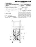
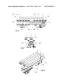
[0020] FIG. 1 is a front view of a device according to the invention;
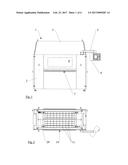
[0021] FIG. 2 is a top view of the device;
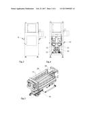
[0022] FIG. 3 is a side view of the device;
[0023] FIG. 4 is a side view of the device with casing removed and without the frame;
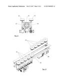
[0024] FIG. 5 is an isometric view of the device without the casing and without the frame;
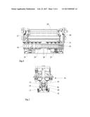
[0025] FIG. 6 is a front view of the device without the casing and without the frame;
[0026] FIG. 7 is a side view of the device without the casing;
[0027] FIG. 8 is an enlarged front view of the device in section without the casing;
[0028] FIG. 9 is a view along arrow IX in FIG. 8;
[0029] FIG. 10 is an isometric view;
[0030] FIG. 11 is an enlarged view of a common carrier for two tool holders in a side view;
[0031] FIG. 12 is an isometric view;
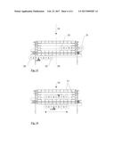
[0032] FIG. 13 is a partially broken top view of a first type of operation of the device according to an embodiment of the invention; and
[0033] FIG. 14 is a partially broken top view of a second type of operation of the device according to an embodiment of the invention.
DETAILED DESCRIPTION OF THE PRESENTLY PREFERRED EMBODIMENTS
[0034] The device 1 according to FIGS. 1 to 3 is virtually completely enclosed by a housing 2 with a hood 3. A viewing window 4 allows the machining processes to be controlled optically. The necessary operating controls are combined in an operating unit 6, which is swivelable on a boom 5. Alternatively, it is also possible to arrange an operating unit of this type in or at the housing, for example. An exhaust installation, not shown, removes dust, chips or the like via a conduit so as to ensure operation that is substantially free from dirt.
[0035] A slot-like inlet opening 7 and outlet opening 8, respectively, are provided on the front side and back side of the housing 2 for workpieces extending substantially two-dimensionally. These workpieces can be fed manually or mechanically, and transporting in the device 1 is carried out by transporting rolls 10 (see FIGS. 6 and 8) arranged beneath the workpiece.
[0036] Surface-elastic pressing rolls 11 (see, for example FIGS. 2, 5, 6, 8 and 14) allow the passage of workpieces having, to some extent, an irregular surface, for example, with bends or the like.
[0037] Tools 12, 13--see FIG. 7--which rotate and/or oscillate around perpendicular axes, and which are arranged one behind the other in direction of passing 14 of a workpiece, are provided for the surface machining of workpieces. As can be seen, for example, in FIG. 4, tools 12, 13 are held in two tool holders 15, 16. For example, every tool holder 15, 16 in this case has five tools 12, 13 (see FIG. 8) which are arranged in each instance in a row transverse to the direction of passing 14. Every tool holder 15, 16 has an electric motor 17, 18 for driving the tools 12, 13 in a group via toothed belts 19, 20.
[0038] The tool holders 15, 16 are movable in a common plane transverse to the direction of passing 14, for which purpose the tool holders 15, 16 are connected to a common carrier 21 via two linear guides 22, 23 in each instance (See FIGS. 8-11). An electric motor 25 (see FIG. 6) is provided for a displacement of the tool holders 15, 16 transverse to the direction of passing 14, this electric motor 25 driving a toothed belt 26 at which tool holders 15, 16 are arranged approximately in the center. As a result of this step, a displacement of the tool holders 15, 16 is carried out in opposite directions synchronously with respect to a center plane extending in direction of passing 14. Likewise, tool holders 15, 16 can oscillate in opposite directions synchronously when the device is operated transverse to the direction of passing 14.
[0039] The common carrier 21 of the tool holders 15, 16 is vertically adjustable for different dimensionings of the workpieces and/or tools. To this end, mechanical actuators 27, 28 (see FIG. 6), which are actuated by only one electric motor, are provided on the right-hand side and left-hand side in direction of passing 14. In order to reliably exclude tilting, the two actuators 27, 28 are mechanically coupled via a driver bar 29 as can be seen, for example, in FIG. 6.
[0040] Different operating methods of the device 1 are explained further referring to the top views in FIGS. 13 and 14.
[0041] The approximately central connection of the tool holders 15, 16 to the toothed belt 26 allows the outer tools 30, 31 to move far out of the working region and, accordingly, enables a simple exchange. The offset of the tool holders 15, 16 is changed for exchanging the inner tools 32, 33 with respect to the direction of passing 14.
[0042] FIG. 13 further shows that the maximum machining width of the device 1 amounts to the sum of the widths of the machining area defined by the tools 30 to 32 and 31 to 33 transverse to the direction of passing 14. The inner tools 32, 33 in direction of passing 14 with reference to a center plane 34 perpendicular to the drawing plane are subject to heavier wear than the outer tools 30, 31. As the wear of the tools 32, 33 increases, only the offset of the two tool holders 15, 16 relative to the center plane 34 needs to be changed, so that tools 30, 31 then form the inner tools and so that tools 30, 31 and 32, 33, respectively, wear uniformly.
[0043] Alternatively, the tool holders 15, 16 according to FIG. 14 can be arranged directly one behind the other. While this does not make optimal use of the potential machining width, the surface machining of workpieces passing through is much more intensive.
[0044] This is true particularly when the two tool holders 15, 16 oscillate in opposite directions according to the double arrow and the tools also rotate and/or oscillate in opposite directions.
[0045] Thus, while there have been shown and described and pointed out fundamental novel features of the invention as applied to a preferred embodiment thereof, it will be understood that various omissions and substitutions and changes in the form and details of the devices illustrated, and in their operation, may be made by those skilled in the art without departing from the spirit of the invention. For example, it is expressly intended that all combinations of those elements and/or method steps which perform substantially the same function in substantially the same way to achieve the same results are within the scope of the invention. Moreover, it should be recognized that structures and/or elements and/or method steps shown and/or described in connection with any disclosed form or embodiment of the invention may be incorporated in any other disclosed or described or suggested form or embodiment as a general matter of design choice. It is the intention, therefore, to be limited only as indicated by the scope of the claims appended hereto.
User Contributions:
Comment about this patent or add new information about this topic:
| People who visited this patent also read: | |
| Patent application number | Title |
|---|---|
| 20180338005 | METHOD AND SYSTEM FOR CONTROLLING AUDIO-VIDEO-NAVIGATION (AVN) OF VEHICLE THROUGH SMART DEVICE |
| 20180338004 | INTERNET OF THINGS INFORMATION SYSTEM |
| 20180338002 | WEB SERVICES-BASED DATA TRANSFERS FOR ITEM MANAGEMENT |
| 20180338000 | RESOURCE ALLOCATION FOR CHANNEL ACCESS IN V2X COMMUNICATION SYSTEMS |
| 20180337998 | REDIRECTION OF I/O REQUESTS TO DISPERSED STORAGE |
Images included with this patent application:
 |  |
 |  |
 |  |
 |
| New patent applications in this class: | |
| Date | Title |
|---|---|
| 2022-09-22 | Electronic device |
| 2022-09-22 | Front-facing proximity detection using capacitive sensor |
| 2022-09-22 | Touch-control panel and touch-control display apparatus |
| 2022-09-22 | Sensing circuit with signal compensation |
| 2022-09-22 | Reduced-size interfaces for managing alerts |