Patent application title: IMPROVED STRUCTURAL ELEMENTS OBTAINED BY LINEAR FRICTION WELDING
Inventors:
IPC8 Class: AB23K20233FI
USPC Class:
1 1
Class name:
Publication date: 2017-02-23
Patent application number: 20170050264
Abstract:
The invention concerns a method for forming by welding along a flat
surface an article. The method according to the invention is particularly
useful to improve strength and elongation of welded joints obtained by
linear friction welding. Structural articles of aircrafts obtained with
the method of the invention are advantageous, in particular aircraft
structural members.Claims:
1. A method for forming by welding along a flat surface an article
comprising at least a first metallic member in the form of an aluminium
alloy wrought product having elongated grains in a longitudinal direction
(L10), with an anisotropy index in a longitudinal oriented surface of at
least 4 according to ASTM E112 and/or an anisotropy index in a planar
oriented surface of at least 1.5 according to ASTM E112 and at least a
second metallic member, wherein the first metallic member is positioned
in contact with the second metallic member so that said longitudinal
direction (L10) of the elongated grains is positioned substantially
within the weld plane, the article is formed by linear friction welding.
2. A method according to claim 1 wherein the transverse direction (T10) of the grains of said first metallic member is substantially perpendicular to the weld plane.
3. A method according to claim 2 wherein the oscillating direction is substantially parallel to the planar direction of the grains (P10) of said first metallic member.
4. A method according to claim 1 wherein said first metallic member is a forge member and wherein said second metallic member is an oscillating member.
5. A method according to claim 1 wherein said first metallic member is in a temper that is not artificially aged, optionally T3 or T4, before welding and wherein a post weld heat treatment is carried out.
6. A method according to claim 5 wherein said second metallic member is in the form of an aluminium alloy wrought product, in a temper that is not artificially aged, having elongated grains in a longitudinal direction (L11), with an anisotropy index in a longitudinal oriented surface of at least 4 according to ASTM E112 and/or an anisotropy index in a planar oriented surface of at least 1.5 according to ASTM E112 and wherein the longitudinal direction of the elongated grains (L11) of said second metallic member is positioned substantially perpendicular to the weld plane.
7. A method according to claim 6 wherein the oscillating direction is substantially parallel to the planar direction of the grains (P11) of said second metallic member.
8. A method according to claim 5 wherein said second metallic member is in the form of an aluminium alloy wrought product, in a temper that is not artificially aged, having elongated grains in a longitudinal direction (L11), with an anisotropy index in a longitudinal oriented surface of at least 4 according to ASTM E112 and/or an anisotropy index in a planar oriented surface of at least 1.5 according to ASTM E112 and wherein said longitudinal direction of the elongated grains of said second metallic member (L11) is positioned substantially within the weld plane.
9. A method according to claim 8 wherein the transverse direction of the grains (T11) of said second metallic member is substantially perpendicular to the weld plane with optionally preferably the oscillating direction substantially parallel to the planar direction of the grains (P11) of said second metallic member.
10. A method according to claim 1 wherein said first metallic member is in a final metallurgical temper, optionally T6, T7X or T8, before welding.
11. A method according to claim 10 wherein said second metallic member is in the form of an aluminium alloy wrought product, in a final metallurgical temper, having elongated grains in a longitudinal direction (L11), with an anisotropy index in a longitudinal oriented surface of at least 4 according to ASTM E112 and/or an anisotropy index in a planar oriented surface of at least 1.5 according to ASTM E112 and wherein said longitudinal direction of the elongated grains (L11) of said second metallic member is positioned substantially within the weld plane.
12. A method according to claim 11 wherein the transverse direction of the grains (T11) of said second metallic member is substantially perpendicular to the weld plane.
13. A method according to claim 12 wherein the oscillating direction is substantially parallel to the planar direction of the grains (P11) of said second metallic member.
14. A method according to claim 1 wherein said first metallic member and optionally preferably said second metallic member are made of an aluminum-lithium type aluminum alloy.
15. A method according to claim 1 wherein said article is a structural article of an aircraft or of an automobile, optionally an aircraft rib.
Description:
TECHNICAL FIELD
[0001] The invention concerns the welding of metal members according to the linear friction welding process. More precisely, it concerns welding together of two members comprising a wrought aluminium member having elongated grains.
BACKGROUND OF THE RELATED ART
[0002] Linear friction welding (LFW) is a welding process which involves the rubbing under pressure of one component across the face of another in a reciprocated motion. The reciprocated motion generates frictional heat which softens the material at the interface, and combined with the normal force, pushes this initial interface material out as flash. This process continues until sufficient material (usually a few millimeters) has "burned-off" and has been expelled as flash, whereupon the oscillation ceases and the two members are rapidly brought ,into alignment and a final "forge force" is maintained to consolidate the joint. Machining or grinding can subsequently remove flash produced during the LFW process. This process has recently attracted interest to assemble aluminium alloys.
[0003] Patent application U.S. 2003/0168494 describes a method of constructing a preform for use in forming a machined structural assembly wherein members are friction welded.
[0004] Patent application U.S. 2007/0084905 describes a method of making a tailored blank using friction welding wherein structural members are disposed with oblique angles.
[0005] As recognized in patent application U.S. 2006/054252 one drawback of LFW is a significant drop in ultimate tensile strength and elongation compared to the parent metal. The loss of ductility can in some instance make impractical or even impossible to use the LFW assembled members. It has been proposed to use further thermal treatments in order to
[0006] It should be noted that for a welding assembly, elongation is at least in part an indication of how localized within the welding zone the strain is. Mechanical properties are affected in the welding zone, when elongation is improved it can mean that the welding zone is smaller.
[0007] Depending on the size and the shape of the structural assembly it may not be possible to realize a post-welding heat treatment; the structural assembly in certain cases has to be used as welded and further machined. Even when a post-weld thermal treatment is realized it would be useful to further improve the mechanical properties of the welded joint.
[0008] The problem solved by the present invention is to improve the mechanical properties of the welded joint obtained by linear friction welding. In particular, it would be advantageous to improve elongation of the welded assembly which as explained relates to reducing the extension of the zone affected by welding. It is also needed to improve the balance between strength and fatigue properties of the welded assembly.
PURPOSE OF THE INVENTION
[0009] An object of the present invention is a method for forming by welding along a flat surface an article comprising at least a first metallic member (10) in the form of an aluminium alloy wrought product having elongated grains in a longitudinal direction (L10), with an anisotropy index in a longitudinal oriented surface of at least 4 according to ASTM E112 and/or an anisotropy index in a planar oriented surface of at least 1,5 according to ASTM E112
[0010] and at least a second metallic member (11), wherein
[0011] the first metallic member (10) is positioned in contact with the second metallic member so that said longitudinal direction (L10) of the elongated grains is positioned substantially within the weld plane,
[0012] the article is formed by linear friction welding.
DESCRIPTION OF THE FIGURES
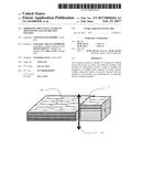
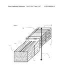
[0013] FIG. 1 is a general diagram describing the linear friction welding process.
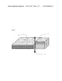
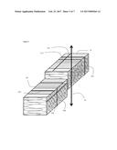
[0014] FIG. 2 illustrates the notation according to ASTM E112 used to define grain orientations
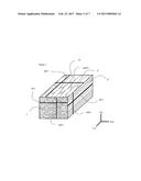
[0015] FIG. 3 illustrates the notation used for the examples.
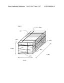
[0016] FIG. 4 illustrates an embodiment of the invention
[0017] FIG. 5 illustrates an embodiment of the invention
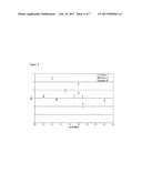
[0018] FIG. 6 illustrates the balance between strength and elongation for example 1.
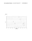
[0019] FIG. 7 illustrates the balance between strength and elongation for example 2.
DESCRIPTION OF THE INVENTION
[0020] The alloys are designated in compliance with the rules of The Aluminium Association (AA), known to the person skilled in the art. The definitions of metallurgical states are indicated in European standard EN 515.
[0021] Unless otherwise stipulated, the static mechanical characteristics, in other words the ultimate tensile strength UTS, the 0.2% offset tensile yield stress TYS and elongation at break E, are determined by a tensile test in accordance with standard EN ISO 6892-1; the sampling and the direction of the test being defined by standard EN 485-1. For welded assemblies, a gauge length of 30 mm is used to calculate TYS and E.
[0022] Fatigue tests were carried out according to ASTM E466-07 for test samples FPE 5A Kt 1.032 (flat samples with a thickness of 3mm) under the following parameters : frequency of oscillations: f=50 Hz, oscillation maximal stress: .sigma.=275 MPa, Ratio minimum/maximum stress: R=0.1, Maximal number of cycles allowed: N=1 000 000 cycles.
[0023] FIG. 1 describes a linear friction welding operation. Two members (10) and (11) are placed side by side. One member is placed into oscillatory motion along the oscillation direction and then the two members are brought to contact. Member (10), which is for example the forge member, is fixed whereas member (11), which is then the oscillating member, is oscillating along the oscillating direction (12).
[0024] The normal force is increased progressively to a set friction pressure, the frequency and amplitude of oscillations being also set. The soft material layer is no longer able to support the normal force and is extruded into the "flash". The material at the interface is no longer under sliding friction in this phase.
[0025] The oscillatory motion is reduced after a desired parameter has been reached: burn-off (LFW parameter for axial shortening limit value in mm), absolute position in mm, time in s, or a combination of these three. The two components are aligned, the normal force increases up to the value of the forge pressure parameter. This phase is called the deceleration phase. Finally the forge phase allows the resultant joint to cool down whilst an axial compressive force, the forging pressure, is maintained.
[0026] For a given metal alloy, in a given metallurgical temper, welding parameters may be optimized to obtain a weld whose visual quality is satisfactory and whose mechanical strength and/or elongation is maximized while using the fastest welding speed possible. The welding parameters are essentially defined by the oscillation amplitude and frequency, the friction pressure, the forge pressure and the burn-off (mm).
[0027] The invention concerns linear friction welding of at least a first metallic member (10) in the form of an aluminum alloy wrought product having elongated grains in a longitudinal direction (L10), with an anisotropy index in a longitudinal oriented surface of at least 4 according to ASTM E112 and/or an anisotropy index in a planar oriented surface of at least 1,5 according to ASTM E112 and at least a second metallic member (11).
[0028] FIG. 2 shows the grain orientation of the aluminum alloy wrought member (10), with symbols in accordance to FIG. 7 of standard ASTM E112. The longitudinal direction of the grains is along test line l(0.degree. for the longitudinal oriented surface or p(0.degree.) for the planar oriented surface . The transverse direction of the grains is along test line l(90.degree.) for the longitudinal oriented surface or t(90.degree.) for the transverse oriented surface . The planar direction of the grains is along test line t(0.degree.) for the transverse oriented surface or p(90.degree.) for the planar oriented surface . For convenience in the present application the longitudinal direction of the grains l(0.degree.), p(0.degree.) is also referred to as L, the transverse direction l(90.degree.), t(90.degree.) is also referred to as T and the planar direction t(0.degree.), p(90.degree.) is also referred to as P, with additional numbers to represent the considered member. For example L10 is the longitudinal direction of the first member (10).
[0029] Typically, the aluminium alloy wrought product is a rolled, forged or extruded product that has been sufficiently worked to obtain elongated grains with an anisotropy index in a longitudinal oriented surface of at least 4 according to ASTM E112 and/or an anisotropy index in a planar oriented surface of at least 1,5 according to ASTM E112. Preferably, the anisotropy index in the longitudinal oriented surface is of at least 6 or even at least 8 according to ASTM E112 and/or the anisotropy index in the planar oriented surface is at least 2 or even at least 4 according to ASTM E112.
[0030] The present inventors have found that by using specific grain orientation during LFW it is possible to significantly improve the mechanical properties of the weld. Usually, metallic members are welded with the longitudinal direction of the elongated grains substantially perpendicular to the weld plane because the mechanical properties of the members are higher in the longitudinal direction and it is expected to be beneficial to load a welded article along this direction.
[0031] According to the present invention an improved weld performance is obtained when the longitudinal direction of the elongated grains (L10) of at least the first metallic member (10) is positioned substantially within the weld plane, as shown for example in FIG. 4. Surprisingly, the most classical grain orientation during LFW for which the direction of the elongated grains is substantially perpendicular to the weld plane provides lower strength and/or elongation than the present invention. By substantially it is meant within the present invention that a difference of a few degrees, typically less than 10 degrees or even less than 5 degrees compared to the strictly "within" or "perpendicular" conditions does not significantly affect the results.
[0032] Even more advantageous elongation is obtained in an embodiment where the transverse direction of the grains (T10) of said first metallic member (10) is substantially perpendicular to the weld plane with preferentially the oscillating direction substantially parallel to the planar direction of the grains (P10) of said first metallic member (10). It may be advantageous in another embodiment to have the transverse direction of the grains, (T10) of said first metallic member substantially within the weld plane, in order to obtain an improved combination of strength and fatigue. Advantageously said first metallic member (10) is the forge member and said second metallic member (11) is the oscillating member.
[0033] In an embodiment of the present invention, which is referred to for convenience as "welding before aging" embodiment, said first metallic member is linear friction welded in a temper that is not artificially aged, typically a T3 or T4 temper, and a post-weld heat treatment, is then carried out. The post-weld heat treatment may include solution heat treatment and/or quenching and/or aging. Preferably, the post-weld heat treatment is an aging treatment carried out at a temperature between 120.degree. C. and 180.degree. C. during 10 to 80 hours. The welded article is typically put in a furnace in order to carry out the post-weld heat treatment. It is advantageous in a first "welding before aging" embodiment that said second metallic member (11) is in the form of an aluminium alloy wrought product, in a temper that is not artificially aged, having elongated grains in a longitudinal direction (L11) with an anisotropy index in a longitudinal oriented surface of at least 4 according to ASTM E112 and/or an anisotropy index in a planar oriented surface of at least 1,5 according to ASTM E112 and wherein the longitudinal direction (L11) of the elongated grains of said second metallic member (11) is positioned substantially perpendicular the weld plane. Preferentially in this first "welding before aging" embodiment the oscillating direction is substantially parallel to the planar direction of the grains (P11) of said second metallic member (11). This first "welding before aging" embodiment may be illustrated for example by FIG. 4.
[0034] It is advantageous in a second "welding before aging" embodiment that said second metallic member (11) is in the form of an aluminium alloy wrought product, in a temper that is not artificially aged, having elongated grains in a longitudinal direction (L11) with an anisotropy index in a longitudinal oriented surface of at least 4 according to ASTM E112 and/or an anisotropy index in a planar oriented surface of at least 1,5 according to ASTM E112 and wherein the longitudinal direction (L11) of the elongated grains of said second metallic member (11) is positioned substantially within the weld plane and wherein the transverse direction of the grains (T11) of said second metallic member (11) is substantially perpendicular to the weld plane. Preferentially in this second "welding before aging" embodiment the oscillating direction is substantially parallel to the planar direction of the grains (P11) of said second metallic member (11). This second "welding before aging" embodiment may be illustrated for example by FIG. 5. Preferably, the anisotropy index in the longitudinal oriented surface is of at least 6 or even at least 8 according to ASTM E112 and/or the anisotropy index in the planar oriented surface is at least 2 or even at least 4 according to ASTM E112.
[0035] It should be noted that in the "welding before aging" embodiment the joint efficiency is particularly high. If the joint efficiency is defined for convenience as the ratio of ultimate tensile strength of the welded article to the ultimate tensile strength in the L direction of initial member, the joint efficiency in the "welding before aging" embodiment is at least 90% and preferably at least 92%.
[0036] In another embodiment of the present invention, which is referred to for convenience "welding after aging" said first metallic member is in a final metallurgical temper, typically T6, T7X or T8, before welding. Final metallurgical temper refers to the metallurgical temper that is used in the final product and is not modified by a further aging treatment. Typically a final metallurgical temper for an aluminium alloy containing Li is a T8 temper, for a 7XXX series alloys it is typically a T6 or a T7X temper, for a 2XXX series alloy which does not contain Li it may also be a T3 or T4 temper.
[0037] It is advantageous in the "welding after aging" embodiment that said second metallic member (11) is in the form of an aluminium alloy wrought product, in a final metallurgical temper, having elongated grains in a longitudinal direction (L11), with an anisotropy index in a longitudinal oriented surface of at least 4 according to ASTM E112 and/or an anisotropy index in a planar oriented surface of at least 1,5 according to ASTM E112 and wherein said longitudinal direction of the elongated grains of said second metallic member is positioned substantially within the weld plane. Advantageously in the "welding after aging" embodiment the transverse direction of the grains (T11) of said second metallic member is substantially perpendicular to the weld plane and preferably the oscillating direction is substantially parallel to the planar direction of the grains (P11) of said second metallic member.
[0038] In another embodiment of "welding after aging" embodiment, which may in some instances the fatigue performance, the transverse direction of the grains (T11) of said second metallic member is substantially within the weld plane.
[0039] This invention allows members made of dissimilar metal alloys to be welded. This may concern, for example, two aluminum alloys whose yield stress is different, or an aluminum alloy and another metal such as a titanium alloy, steel, a copper alloy or a nickel based alloy. Particularly advantageous properties are obtained when the first metallic member and the second metallic member are made of aluminum alloys.
[0040] Among aluminum alloys the invention is advantageous in particular for the alloys of the 2XXX, 3XXX, 5XXX, 6XXX, 7XXX and 8XXX families. The invention is particularly advantageous for linear friction welding of members made of aluminum-lithium type aluminum alloy, i.e. containing at least about 0.5% lithium by weight.
[0041] Within the scope of this invention, 2XXX alloy members selected from the group AA2X39, AA2X24, AA2X50, AA2X55, AA2X60, AA2X76, AA2X95, AA2X96, AA2X98, AA2X99, are particularly advantageous and 7XXX alloy members selected from the group AA7X10, AA7X40, AA7X49, AA7X50, AA 7X75, AA7X81, AA7X85, AA7X99 are particularly advantageous.
[0042] The invention method is particularly advantageous to manufacture structural articles, particularly for automobiles or aircrafts. "Structural article" of a mechanical construction here refers to a mechanical part for which the static and/or dynamic mechanical properties are particularly important for the performance of the structure, and for which a structural analysis is usually prescribed or performed. These are typically articles the failure of which is likely to endanger the safety of said construction, its users or others. For an aircraft, these structural articles include the parts which make up the fuselage (such as the fuselage skin, stringers, bulkheads, circumferential frames), the wings (such as the upper or lower wing skin, stringers or stiffeners, ribs and spars) and the tail unit, made up of horizontal and vertical stabilizers, as well as floor beams, seat tracks and doors. The invention method is particularly suited for the manufacture of ribs.
EXAMPLES
Example 1
[0043] Articles made by linear friction welding of AA2050 rolled members in a T8 temper have been prepared. This example illustrates the "welding after aging" embodiment. The AA2050 members were 75.times.40.times.25 mm coupons cut from a plate. The AA2050 members had elongated grains in a longitudinal direction with an anisotropy index in a longitudinal oriented surface of 8.75 according to ASTM E112 and an anisotropy index in a planar oriented surface of 2.5 according to ASTM E112. Grain orientation references are conform to ASTM E112 FIG. 7 and are represented in FIG. 2. The coupons were linear friction welded by contacting the 40.times.25 mm sections, the oscillating direction was the direction of the 25 mm dimension. The mechanical properties of the AA2050 T8 plate are provided in Table 1.
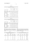
TABLE-US-00001 TABLE 1 Mechanical properties of the AA2050 plate in T8 temper used for welding TYS UTS Elongation Direction (MPa) (MPa) (%) L 514 544 11.4 LT 480 528 8.2 ST 450 523 3.9
[0044] The orientation of the various test samples is provided in Tables 2a and 2b. As an example the forge part coupon of test samples 5 and 6 is presented FIG. 3 which shows the direction of the 25 mm, 45 mm and 75 mm dimensions. The configuration of test samples 5 and 6 is presented in FIG. 5. Test samples 1 and 2 are reference test samples and test samples 3 to 9 are according to the invention.
TABLE-US-00002 TABLE 2a Grain orientation of the forge member section 75 .times. 25 40 .times. 25 75 .times. 40 Longitudinal Transverse Dimension direction vs direction vs Test 75 25 40 25 75 40 weld plane weld plane sample mm mm mm mm mm mm Perpendicular Within 1 l(0.degree.) l(90.degree.) t(0.degree.) t(90.degree.) p(0.degree.) p(90.degree.) Perpendicular Within 2 l(0.degree.) l(90.degree.) t(0.degree.) t(90.degree.) p(0.degree.) p(90.degree.) Within Within 3 p(90.degree.) p(0.degree.) l(90.degree.) l(0.degree.) t(0.degree.) t(90.degree.) Within Within 4 p(90.degree.) p(0.degree.) l(90.degree.) l(0.degree.) t(0.degree.) t(90.degree.) Within Perpendicular 5 t(90.degree.) t(0.degree.) p(0.degree.) p(90.degree.) l(90.degree.) l(0.degree.) Within Perpendicular 6 t(90.degree.) t(0.degree.) p(0.degree.) p(90.degree.) l(90.degree.) l(0.degree.) Perpendicular Within 7 l(0.degree.) l(90.degree.) t(0.degree.) t(90.degree.) p(0.degree.) p(90.degree.) Within Perpendicular 8 t(90.degree.) t(0.degree.) p(0.degree.) p(90.degree.) l(90.degree.) l(0.degree.) Within Within 9 p(90.degree.) p(0.degree.) l(90.degree.) l(0.degree.) t(0.degree.) t(90.degree.)
TABLE-US-00003 TABLE 2b Grain orientation of the oscillating member section 75 .times. 25 40 .times. 25 75 .times. 40 Longitudinal Transverse Dimension direction vs direction vs Test 75 25 40 25 75 40 weld plane weld plane sample mm mm mm mm mm mm Perpendicular Within 1 l(0.degree.) l(90.degree.) t(0.degree.) t(90.degree.) p(0.degree.) p(90.degree.) Perpendicular Within 2 l(0.degree.) l(90.degree.) t(0.degree.) t(90.degree.) p(0.degree.) p(90.degree.) Within Within 3 p(90.degree.) p(0.degree.) l(90.degree.) l(0.degree.) t(0.degree.) t(90.degree.) Within Within 4 p(90.degree.) p(0.degree.) l(90.degree.) l(0.degree.) t(0.degree.) t(90.degree.) Within Perpendicular 5 t(90.degree.) t(0.degree.) p(0.degree.) p(90.degree.) l(90.degree.) l(0.degree.) Within Perpendicular 6 t(90.degree.) t(0.degree.) p(0.degree.) p(90.degree.) l(90.degree.) l(0.degree.) Within Perpendicular 7 t(90.degree.) t(0.degree.) p(0.degree.) p(90.degree.) l(90.degree.) l(0.degree.) Within Within 8 p(90.degree.) p(0.degree.) l(90.degree.) l(0.degree.) t(0.degree.) t(90.degree.) Perpendicular Within 9 l(0.degree.) l(90.degree.) t(0.degree.) t(90.degree.) p(0.degree.) p(90.degree.)
[0045] Welding was realized on a E20 machine manufacture by Thomson friction welding. The welding conditions are provided in Table 3. The burn-off was 2.5 mm for all the samples.
TABLE-US-00004 TABLE 3 Experimental linear friction welding parameters Frequency Amplitude of of Friction Forge Test oscillations oscillations pressure pressure sample (Hz) (mm) (MPa) (MPa) 1 50 3 120 120 2 40 2 150 150 3 40 2 150 150 4 50 3 120 120 5 40 2 150 150 6 50 3 120 120 7 40 2 150 150 8 40 2 150 150 9 40 2 150 150
[0046] The results of the tensile tests of the welded articles (L.sub.0=30 mm) and of the fatigue tests are provided in Table 4. The balance between ultimate tensile strength (R.sub.m) and elongation is presented in FIG. 6.
TABLE-US-00005 TABLE 4 Mechanical testing of the welded samples. Fatigue Test TYS UTS Elongation (number sample (MPa) (MPa) (%) of cycles) 1 320 410 3.2 1376690 2 342 413 2.8 138559 3 344 424 2.6 866535 4 322 419 3.1 149011 5 317 412 5.3 65780 6 315 418 4.6 111675 7 329 417 3.1 1246291 8 330 418 3.5 110444 9 329 415 3.8 128592
[0047] FIG. 6 shows that all the test samples according to the invention, having the longitudinal direction of the elongated grains for the forge member or the oscillating member positioned within the weld plane, exhibit a better balance of strength and elongation than examples 1 and 2 which do not have this feature. FIG. 6 also shows that test samples 5 and 6 which have the transverse direction of the grains, l(90.degree.), t(90.degree.) perpendicular to the weld plane for the forge member and the oscillating member, and have been welded with two different sets of linear friction welding process conditions, exhibit the best balance between strength and elongation. It is noted however that test sample 3 which has the transverse direction of the grains, l(90.degree.), t(90.degree.) substantially within the weld plane for the forge member and the oscillating member exhibits high strength and high fatigue performance.
Example 2
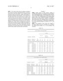
[0048] Articles made by linear friction welding of AA2050 rolled members in a T3 temper have been prepared. This example illustrates the "welding before aging" embodiment. The AA2050 members were 75.times.40.times.25 mm coupons cut into a plate. The AA2050 members had elongated grains similar to those of the AA2050 T8 members of example 1. The coupons were linear friction welded by contacting the 40.times.25 mm sections, the oscillating direction was the direction of the 25 mm dimension. Following the welding operation, a post-weld heat treatment of 18 hours at 155 .degree. C. was carried out.
[0049] The orientation of the various test samples is provided in Tables 5a and 5b. Test sample 10 is a reference test sample and test samples 11 to 17 are according to the invention.
TABLE-US-00006 TABLE 5a Grain orientation of the forge member Section 75 .times. 25 40 .times. 25 75 .times. 40 Longitudinal Transverse Dimension direction vs direction vs Test 75 25 40 25 75 40 weld plane weld plane sample mm mm mm mm mm mm Perpendicular Within 10 l(0.degree.) l(90.degree.) t(0.degree.) t(90.degree.) p(0.degree.) p(90.degree.) Within Perpendicular 11 l(90.degree.) l(0.degree.) p(90.degree.) p(0.degree.) t(90.degree.) t(0.degree.) Within Perpendicular 12 l(90.degree.) l(0.degree.) p(90.degree.) p(0.degree.) t(90.degree.) t(0.degree.) Within Perpendicular 13 l(90.degree.) l(0.degree.) p(90.degree.) p(0.degree.) t(90.degree.) t(0.degree.) Within Perpendicular 14 t(90.degree.) t(0.degree.) p(0.degree.) p(90.degree.) l(90.degree.) l(0.degree.) Within Perpendicular 15 l(90.degree.) l(0.degree.) p(90.degree.) p(0.degree.) t(90.degree.) t(0.degree.) Within Perpendicular 16 l(90.degree.) l(0.degree.) p(90.degree.) p(0.degree.) t(90.degree.) t(0.degree.) Within Perpendicular 17 t(90.degree.) t(0.degree.) p(0.degree.) p(90.degree.) l(90.degree.) l(0.degree.)
TABLE-US-00007 TABLE 5b Grain orientation of the oscillating member Section 75 .times. 25 40 .times. 25 75 .times. 40 Longitudinal Transverse Dimension direction vs direction vs Test 75 25 40 25 75 40 weld plane weld plane sample mm mm mm mm mm mm Perpendicular Within 10 l(0.degree.) l(90.degree.) t(0.degree.) t(90.degree.) p(0.degree.) p(90.degree.) Perpendicular Within 11 l(0.degree.) l(90.degree.) t(0.degree.) t(90.degree.) p(0.degree.) p(90.degree.) Perpendicular Within 12 l(0.degree.) l(90.degree.) t(0.degree.) t(90.degree.) p(0.degree.) p(90.degree.) Perpendicular Within 13 p(0.degree.) p(90.degree.) t(90.degree.) t(0.degree.) l(0.degree.) l(90.degree.) Perpendicular Within 14 p(0.degree.) p(90.degree.) t(90.degree.) t(0.degree.) l(0.degree.) l(90.degree.) Within Within 15 t(0.degree.) t(90.degree.) l(0.degree.) l(90.degree.) p(0.degree.) p(90.degree.) Within Perpendicular 16 l(90.degree.) l(0.degree.) p(90.degree.) p(0.degree.) t(90.degree.) t(0.degree.) Within Perpendicular 17 t(90.degree.) t(0.degree.) p(0.degree.) p(90.degree.) l(90.degree.) l(0.degree.)
[0050] Welding was realized on a E20 machine manufacture by Thomson friction welding. The welding conditions were the same as those of references 1, 4 and 6 of example 1, except that for sample 17, burn-off was 1 mm.
[0051] The results of the tensile tests of the welded articles (L.sub.0=30 mm) and of the fatigue tests are provided in Table 6. The balance between ultimate tensile strength (R.sub.m) and elongation is presented in FIG. 7.
TABLE-US-00008 TABLE 6 Mechanical testing of the welded samples. Fatigue Test TYS UTS Joint Elongation (number sample (MPa) (MPa) efficiency (%) of cycles) 10 478 514 94% 1.7 193735 11 462 511 94% 3.0 55608 12 463 514 94% 3.7 102722 13 467 513 94% 3.2 390041 14 459 501 92% 9.1 143941 15 442 491 90% 3.3 127486 16 432 487 90% 5.1 65802 17 448 504 93% 6.8 192954
[0052] Invention test samples exhibit significantly improved elongation compared to the reference test sample.
[0053] Very high elongation is obtained for test sample 14, wherein the longitudinal direction of the elongated grains of the forge member is within the weld plane and the longitudinal direction of the elongated grains of the oscillating member is perpendicular to the weld plane. Test sample 17 also exhibit a significantly improved balance between strength and elongation Fatigue results for invention test samples are usually similar and sometimes higher than fatigue results of the reference sample.
Example 3
[0054] Articles made by linear friction welding of AA2050 rolled members in a T8 temper have been prepared. This example illustrates the specific technical effect of anisotropy indexes. The AA2050 members were 75.times.40.times.25 mm coupons cut from a plate. The AA2050 members had an ultimate tensile strength of 523 MPa and a departure from an equiaxed shape which was not severe. The coupons were linear friction welded by contacting the 40.times.25 mm sections, the oscillating direction was the direction of the 25 mm dimension.
[0055] Welding was realized on a E20 machine manufacture by Thomson friction welding. The welding conditions were the same as those of references 1, 4 and 6 of example 1.
[0056] The results of the tensile tests of the welded articles (L.sub.0=30 mm) and of the fatigue tests are provided in Table 7. The balance between ultimate tensile strength (R.sub.m) and elongation is presented in FIG. 6 (sample 18).
TABLE-US-00009 TABLE 7 Mechanical testing of the welded samples. Test TYS UTS Joint Elongation sample (MPa) (MPa) efficiency (%) 18 334 419 80% 2
[0057] Invention test samples exhibit significantly improved elongation so as a better balance between strength and elongation compared to the test sample 18.
User Contributions:
Comment about this patent or add new information about this topic:
Images included with this patent application:
 |  |
 |  |
 |  |
 |  |
 |  |
| Similar patent applications: | |
| Date | Title |
|---|---|
| 2017-04-13 | Use of biomarkers for assessing treatment of gastrointestinal inflammatory disorders with beta7 integrin antagonists |
| 2017-04-13 | Method to optimize the treatment of patients with biological drugs |
| 2017-04-13 | Early diagnosis of autoimmune and inflammatory disorders |
| 2017-04-13 | New biomarker for outcome in aml patients |
| 2017-04-13 | Rare molecule detection |
| New patent applications in this class: | |
| Date | Title |
|---|---|
| 2022-09-22 | Electronic device |
| 2022-09-22 | Front-facing proximity detection using capacitive sensor |
| 2022-09-22 | Touch-control panel and touch-control display apparatus |
| 2022-09-22 | Sensing circuit with signal compensation |
| 2022-09-22 | Reduced-size interfaces for managing alerts |