Patent application title: DETERMINING THE CONVERSION EFFICIENCY OF AN EXHAUST GAS CATALYTIC CONVERTER
Inventors:
Frank Keller (Schönaich, DE)
Peter Hohner (Stuttgart, DE)
Stefanos Tzivanakis (Winnenden, DE)
Thomas Baumann (Kornwestheim, DE)
IPC8 Class: AF01N1100FI
USPC Class:
1 1
Class name:
Publication date: 2017-02-16
Patent application number: 20170044962
Abstract:
In order to determine the conversion efficiency of at least one component
of a catalytic converter box comprising at least one SCR catalytic
converter and an oxides of nitrogen storage catalytic converter for the
aftertreatment of the exhaust gases of an internal combustion engine,
wherein the catalytic converter box is associated at the downstream end
with a NO.sub.x sensor, at least for a limited period of time the
internal combustion engine is operated such that a first of the two
components does not affect the signal detected by means of the NO.sub.x
sensor and the conversion efficiency of the second component is
determined depending on the signal of the NO.sub.x sensor that is not
affected by the first component.Claims:
1. A method for determining conversion efficiency of at least one
component of a catalytic converter box (6) comprising first and second
components, wherein the first component is at least one SCR catalytic
converter (7) and the second component is an oxides of nitrogen storage
catalytic converter (8), for aftertreatment of exhaust gases of an
internal combustion engine (1), wherein a NO.sub.x sensor (9) is disposed
downstream of the catalytic converter box (6), characterized in that at
least for a limited period of time the internal combustion engine (1) is
operated such that one of the first and second components does not affect
a signal detected by means of the NO.sub.x sensor (9) and the conversion
efficiency of an other of the first and second components is determined
depending on a signal of the NO.sub.x sensor (9) that is unaffected by
the one of the first and second components.
2. The method according to claim 1, characterized in that for a limited period of time the internal combustion engine (1) is operated such that a reduction of the NH.sub.3 stored in the SCR catalytic converter (7) occurs and if no or almost no more NH.sub.3 is stored, the conversion efficiency of the oxides of nitrogen storage catalytic converter (8) is determined depending on the signal of the NO.sub.x sensor.
3. The method according to claim 2, characterized in that the internal combustion engine (1) is operated for the limited period of time such that the SCR catalytic converter (7) reaches a temperature at which the stored NH.sub.3 is released.
4. The method according to claim 2, characterized in that the internal combustion engine (1) is operated such that a feed of NH.sub.3 to the SCR catalytic converter (7) is at least substantially prevented and a reduction of NO.sub.x is carried out using the stored NH.sub.3.
5. The method according to any claim 1, characterized in that the internal combustion engine (1) is operated at least for a limited period of time such that saturation of the oxides of nitrogen storage catalytic converter (8) with NO.sub.x takes place, and if no or almost no more NO.sub.x can be stored the conversion efficiency of the SCR catalytic converter (7) is determined depending on the signal of the NO.sub.x sensor (9).
6. The method according to claim 1, characterized in that the oxides of nitrogen storage catalytic converter (8) is loaded with NO.sub.x at least until a NO.sub.x slip is measured at the NO.sub.x sensor, an operating mode is selected in which a fully operational or at least sufficiently operational SCR catalytic converter (7) would convert the entire NO.sub.x concentration in the exhaust gas and the conversion efficiency of the SCR catalytic converter (7) is determined depending on the signal of the NO.sub.x sensor (9).
7. The method according to claim 1, characterized in that the NH.sub.3 storage capacity of the SCR catalytic converter (7) is concluded depending on the signal of the NO.sub.x sensor (9).
8. The method according to claim 7, characterized in that NH.sub.3 desorption owing to the NH.sub.3 arising in the NO.sub.x stored in the oxides of nitrogen storage catalytic converter (8) is taken into account when determining the NH.sub.3 storage capacity of the SCR catalytic converter (7).
9. The method according to claim 7, characterized in that NH.sub.3 desorption owing to the NH.sub.3 arising in the NO.sub.x stored in the oxides of nitrogen storage catalytic converter (8) is suppressed by operating the internal combustion engine (1) before the detection of the signal of the NO.sub.x sensor (9) such that the NO.sub.x stored in the oxides of nitrogen storage catalytic converter (8) is released.
10. The method according to claim 7, characterized in that the internal combustion engine (1) is operated with a rich fuel mixture, while the signal of the NO.sub.x sensor (9) is analyzed for determining the NH.sub.3 storage capacity of the SCR catalytic converter (7).
11. The method according to claim 7, characterized in that the internal combustion engine (1) is operated with an only slightly rich fuel mixture, while the signal of the NO.sub.x sensor (9) is analyzed for determining the NH.sub.3 storage capacity of the SCR catalytic converter (7).
12. The method according to claim 7, characterized in that the internal combustion engine (1) is operated with an only slightly rich fuel mixture, with a target lambda value greater than 0.97, while the signal of the NO.sub.x sensor (9) is analyzed for determining the NH.sub.3 storage capacity of the SCR catalytic converter (7).
13. The method according to claim 7, wherein the oxides of nitrogen-storage catalytic converter (8) is disposed in the flow of exhaust gas upstream of the SCR catalytic converter (7), characterized in that the NH.sub.3 store of the SCR catalytic converter (7) and the NO.sub.x store of the oxides of nitrogen storage catalytic converter (8) are emptied and then by operating the internal combustion engine (1) with a rich fuel mixture, NH.sub.3 is produced in the flow of exhaust gas and the signal of the NO.sub.x sensor (9) is analyzed to determine the NH.sub.3 storage capacity of the SCR catalytic converter (7).
14. A non-transitory computer-readable medium storing a computer program (14) that when executed performs a set of functions for controlling an internal combustion engine (1), the set of functions comprising the steps of claim 1.
15. A control unit (11) for controlling the operation of an internal combustion engine (1), the control unit (11) comprising: non-transitory computer-readable medium storing a computer program (14) that when executed in the control unit (11) controls an internal combustion engine (1) by performing the steps of claim 1.
Description:
BACKGROUND OF THE INVENTION
[0001] The invention concerns a method for determining the conversion efficiency of at least one component of a catalytic converter box comprising at least one SCR catalytic converter and an oxides of nitrogen storage catalytic converter for aftertreatment of the exhaust gases of an internal combustion engine, wherein the catalytic converter box is associated with a NO.sub.x sensor at the downstream end.
[0002] The invention further concerns a computer program that can be stored in a control unit for controlling and/or regulating an internal combustion engine. The invention also concerns a control unit for controlling and/or regulating the operation of an internal combustion engine.
[0003] In order to reduce the NO.sub.x emissions, exhaust gas aftertreatment components for converting NO.sub.x into harmless emissions are used with internal combustion engines and especially with gasoline engines with lean burn modes and with diesel engines. The components that are currently mainly used are the oxides of nitrogen storage catalytic converter (NO.sub.x Storage-Catalyst, NSC) and the SCR catalytic converter (Selective Catalytic Reduction).
[0004] The oxides of nitrogen storage catalytic converter stores the oxides of nitrogen (NO.sub.x) present in the flow of exhaust gas. When the storage catalytic converter is sufficiently full, the stored oxides of nitrogen are converted into harmless molecules in a special operating mode of the internal combustion engine, which is referred to as the regeneration phase or as regeneration and in which the internal combustion engine is operated with a rich fuel mixture, and are removed from the storage catalytic converter. The NO.sub.x storage of the storage catalytic converter depends on the current loading, the temperature and other parameters, for example the so-called space velocity. If the relative loading of the storage catalytic converter increases, then eventually the delivered NO.sub.x material can no longer be stored to a sufficient extent. The part that can no longer be stored exits as so-called slip of the storage catalytic converter and is consequently emitted in the flow of exhaust gas.
[0005] The conversion efficiency of the oxides of nitrogen storage catalytic converter depends on the storage behavior. This is usually initially described by a model, which is then adjusted using measurements with a NO.sub.x sensor for the storage catalytic converter concerned, which is referred to as adaptation. During the adaptation, a quality factor is calculated that describes the conversion efficiency of the storage catalytic converter. Using the quality factor, the amount of NO.sub.x that can be stored and the time from which NO.sub.x slip arises can be calculated. An accurate adaptation between the model and the measured sensor value is thus important in order to be able to use the storage catalytic converter optimally and to keep the oxides of nitrogen emissions low.
[0006] During the operation of the internal combustion engine, the storage catalytic converter must be diagnosed in order to recognize damage, for example owing to an excessive temperature.
[0007] An SCR catalytic converter also enables the NO.sub.x present in the exhaust gas to be selectively reduced inter alia to nitrogen (N.sub.2) in the presence of residual oxygen in the flow of exhaust gas by catalytic action, for example using ammonia that is fed in. The introduction of ammonia can be carried out actively by means of the targeted dispensing of a urea water solution into the flow of exhaust material or passively by means of an oxidation catalytic converter disposed upstream of the SCR catalytic converter, for example a three-way catalytic converter or an oxides of nitrogen storage catalytic converter, which produces NH.sub.3 during an operating phase in which the internal combustion engine is operated with a rich fuel mixture.
[0008] Moreover, the SCR catalytic converter can store excess NH.sub.3 in a zeolite to a limited extent. The absorption capacity of the catalytic converter depends here on the temperature of the catalytic converter. If the absorption capacity is exceeded, the excess NH.sub.3 exits the catalytic converter as slip. The stored NH.sub.3 in the SCR catalytic converter also enables the reduction of the NO.sub.x at operating points at which no ammonia is introduced.
[0009] With a system of a combination of a SCR catalytic converter and an oxides of nitrogen storage catalytic converter, higher overall NO.sub.x efficiencies are achieved. A combination of said catalytic converters is referred to below as a catalytic converter box, wherein the two components are not necessarily disposed in a common housing.
[0010] For monitoring the NO.sub.x conversion rate or the conversion efficiency, NO.sub.x sensors are usually used downstream of each individual component.
SUMMARY OF THE INVENTION
[0011] It is the object of the invention to determine the quality of the individual components of an overall system consisting of a SCR catalytic converter and an oxides of nitrogen storage catalytic converter, and especially the component of the NO.sub.x conversion of the SCR catalytic converter, in order to be able to determine the ageing thereof. A possibility is also to be shown to enable the conversion efficiency to be determined with sufficient accuracy even if only one individual NO.sub.x sensor is used.
[0012] The object is achieved by a method of the aforementioned type by operating the internal combustion engine at least for a limited period of time such that a first of the two components does not affect the signal detected by means of the NO.sub.x sensor, and the conversion efficiency for the second component is determined depending on the signal of the NO.sub.x sensor that is not affected by the first component.
[0013] According to the invention, consequently a state occurs in which at least one of the components, for example the SCR catalytic converter, is placed into a state in which it is not affected by the signal detected by the NO.sub.x sensor. Here it should be noted that depending on the current operating mode of the internal combustion engine both NO.sub.x (in a lean operating mode) and also NH.sub.3 (in a rich operating mode) can be measured in the flow of exhaust gas by means of a NO.sub.x sensor.
[0014] According to a first possible embodiment, a state is established in which the SCR catalytic converter does not affect the NO.sub.x signal. This is achieved by a reduction of the NH.sub.3 stored in the SCR catalytic converter. For this purpose, according to one version the internal combustion engine is operated at least for a limited period of time such that a reduction of the NH.sub.3 stored in the SCR catalytic converter takes place. If no or almost no more NH.sub.3 is being stored in the SCR catalytic converter, the conversion efficiency of the NO.sub.x storage catalytic converter is determined depending on the signal of the NO.sub.x sensor. In particular, the internal combustion engine can be operated such that the SCR catalytic converter reaches a temperature at which the stored NH.sub.3 is released.
[0015] According to another possible embodiment, the internal combustion engine is operated such that a delivery of NH.sub.3 to the SCR catalytic converter is at least substantially prevented and a reduction of the NO.sub.x by means of the stored NH.sub.3 takes place.
[0016] By means of the method described above, it is achieved that NH.sub.3 is no longer stored the SCR catalytic converter, whereby the SCR no longer influences the NO.sub.x conversion of the overall system. The signal of the NO.sub.x sensor can thus now be used to determine the conversion efficiency of the oxides of nitrogen storage catalytic converter.
[0017] According to another aspect of the invention, the internal combustion engine is operated for at least a limited period of time such that saturation of the NO.sub.x storage catalytic converter with NO.sub.x occurs and, if no or almost no more NO.sub.x can be stored, the conversion efficiency of the SCR catalytic converter is determined depending on the signal of the NO.sub.x sensor. Here a state is consequently established in which the oxides of nitrogen storage catalytic converter is saturated and thus an input of NO.sub.x passes through almost completely unconverted. In particular, if the oxides of nitrogen storage catalytic converter is installed upstream of the SCR catalytic converter, said state can also be established by selecting an engine operating mode in which NO.sub.x raw emissions are produced, so that the storage catalytic converter is fully loaded. If the storage catalytic converter is installed in the flow of exhaust gas downstream of the SCR catalytic converter, it can become filled by operating the internal combustion engine in an operating mode in which the NO.sub.x concentration in the flow of exhaust gas upstream of the catalytic converter box is so high that even for an optimally operating or a new SCR catalytic converter the NO.sub.x contained in the flow of exhaust gas cannot be fully converted. The NO.sub.x slip from the SCR catalytic converter is then stored in the oxides of nitrogen-storage catalytic converter until the same is full.
[0018] If the storage catalytic converter is fully loaded, an adaptation of the SCR catalytic converter can be carried out, because the SCR catalytic converter as the only component now influences the NO.sub.x concentration in the flow of exhaust gas to the NO.sub.x sensor. Thus a diagnosis of the efficiency of the SCR catalytic converter can now be carried out, for example by a comparison of the mass of NO.sub.x introduced into the SCR in comparison with the mass of NO.sub.x at the position of the NO.sub.x sensor.
[0019] According to an advantageous development of the method according to the invention, the NO.sub.x storage catalytic converter is loaded with NO.sub.x at least until a NO.sub.x slip is measured at the NO.sub.x sensor. An operating mode is then selected in which a fully operational or at least sufficiently operational SCR catalytic converter would convert the entire NO.sub.x concentration in the exhaust gas. The conversion efficiency of the SCR catalytic converter is then determined depending on the signal of the NO.sub.x sensor.
[0020] Consequently, the storage catalytic converter is initially loaded here such that a slip occurs. In this case the process can be as previously described. Regeneration of the storage catalytic converter is usually activated in said load state, but is now suppressed or prevented. Instead, a state is established in the overall system in which a NO.sub.x concentration upstream of the catalytic converter box is so high at its maximum that the NO.sub.x would be completely converted with an optimal new SCR catalytic converter with sufficient stored NH.sub.3. In the case of a SCR catalytic converter that is still converting well enough, no NO.sub.x slip would now be measured at the NO.sub.x sensor. If the SCR catalytic converter has aged however, and thus no longer has the property of converting the NO.sub.x sufficiently well, then a NO.sub.x slip is measured at the sensor downstream of the NSC. The ratio between the mass of NO.sub.x flow upstream of the SCR catalytic converter and the mass of NO.sub.x flow measured by means of the NO.sub.x sensor downstream of the SCR catalytic converter can now be used for the calculation of the quality factor or the conversion efficiency of the SCR catalytic converter.
[0021] According to a further embodiment of the method, the NH.sub.3 storage capacity of the SCR catalytic converter is concluded depending on the signal of the NO.sub.x sensor. Said development uses the property of NO.sub.x sensors of being able to measure NH.sub.3 instead of NO.sub.x for a rich fuel mixture. Further, with the NO.sub.x sensor it can be determined whether a rich or weak fuel mixture is currently available. In order to be able to conclude the NH.sub.3 storage capacity of the SCR catalytic converter for the case in which no NO.sub.x sensor is present, the information about the NH.sub.3 in the flow of exhaust gas upstream of the catalytic converter box could be calculated by suitable NO.sub.x raw mass models and/or oxidation catalytic converter models. It should be noted here that when using a NSC as a NH.sub.3 source upstream of the catalytic converter box, a high NH.sub.3 peak arises through the low storage of the NSC, which may also have to be taken into account in the model being used.
[0022] Preferably moreover, NH.sub.3 desorption owing to the NH.sub.3 arising from the NO.sub.x stored in the oxides of nitrogen storage catalytic converter is taken into account when determining the NH.sub.3 storage capacity of the SCR catalytic converter. In particular, NH.sub.3 desorption is to be seen a short time after the changeover from a lean mode into a mode with a rich fuel mixture.
[0023] Said desorption can for example be determined by integrating the NH.sub.3 signal up to a defined time and adding to the NH.sub.3 storage capacity, or by fitting the curve of the NH.sub.3 signal in the region of the NH.sub.3 desorption to the later profile. The NH.sub.3 storage capacity of the SCR catalytic converter can thereby be determined sufficiently precisely from the difference of the NH.sub.3 flowing into the SCR catalytic converter and the NH.sub.3 flowing out from the NO.sub.x storage catalytic converter.
[0024] Alternatively or additionally, it can be provided to inhibit NO.sub.x desorption owing to NH.sub.3 arising from the NO.sub.x stored in the NO.sub.x storage catalytic converter by operating the internal combustion engine before the detection of the signal of the NO.sub.x sensor such that the stored NO.sub.x in the NO.sub.x storage catalytic converter is released. This can for example be achieved by a temperature increase before the measurement.
[0025] According to a preferred embodiment, the NO.sub.x storage capacity of the oxides of nitrogen storage catalytic converter is determined with a preferably only slightly rich fuel mixture, in particular with a lambda value greater than 0.97, because the downstream oxides of nitrogen-catalytic converter can convert the rich components in the mixture (HC and CO) to harmless components (CO.sub.2 and H.sub.2O) by means of the present oxygen storage capacity and thereby only slight exhaust gas emissions arise. Furthermore, in said region of the composition of the mixture the NH.sub.3 produced by the upstream oxidation catalytic converter is greatest.
[0026] If the oxides of nitrogen storage catalytic converter is disposed in the flow of exhaust gas upstream of the SCR catalytic converter, the NH.sub.3 from the desorption of the oxides of nitrogen storage catalytic converter could pass into the SCR catalytic converter and cause errors in the results. This can be prevented by emptying the NH.sub.3 store of the SCR catalytic converter and the NO.sub.x store of the oxides of nitrogen storage catalytic converter, and then by operating the internal combustion engine with a rich fuel mixture NH.sub.3 is produced in the flow of exhaust gas and the signal of the NO.sub.x sensor is analyzed to determine the NH.sub.3 storage capacity of the SCR catalytic converter. If discharging the catalytic converter is achieved by means of a temperature increase, the catalytic converter could thus be cooled to the desired temperature in connection with a homogenous phase, for example with a lambda value=1, without NH.sub.3 and NO.sub.x emissions and NH.sub.3 could be produced by an operating phase with a rich fuel mixture, which would not be affected by the empty oxides of nitrogen storage catalytic converter.
[0027] The object of the invention is also achieved by a computer program that is stored in a control unit for controlling and/or regulating an internal combustion engine by conducting the method according to the invention if the computer program is executed in the control unit. The object is further achieved by a control unit for controlling and/or regulating the operation of an internal combustion engine by a computer program that is stored in the control unit and the method according to the invention is conducted if the computer program is executed in the control unit.
BRIEF DESCRIPTION OF THE DRAWINGS
[0028] Further features, possible applications and advantages of the invention are revealed by the following description of exemplary embodiments, which are described using the figures, wherein the features can be important to the invention both on their own and also in different combinations, without explicit reference again being made thereto. In the figures:
[0029] FIG. 1 shows a schematic representation of some components present in a motor vehicle that are configured to perform the method according to the invention;
[0030] FIG. 2 shows some process steps of a possible embodiment of the method according to the invention in a flow diagram;
[0031] FIG. 3 shows a further flow diagram with process steps of a possible embodiment of the invention;
[0032] FIG. 4 sows some process steps during the performance of the diagnosis of the SCR catalytic converter; and
[0033] FIG. 5 shows a flow diagram with some process steps that can be used for the diagnosis of the SCR catalytic converter by means of NH.sub.3 information.
DETAILED DESCRIPTION
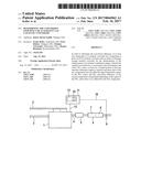
[0034] FIG. 1 shows schematically an internal combustion engine 1 with an induction system 2, a fuel feed 3 and an exhaust system 4. An oxidation catalytic converter 5 (for example a three-way catalytic converter) and a catalytic converter box 6 are disposed in the exhaust system 4. The catalytic converter box 6 comprises a SCR catalytic converter 7 and a NO.sub.x storage catalytic converter 8. A NO.sub.x sensor 9 that is connected to a control unit 11 by means of a data line 10 is disposed downstream of the catalytic converter box 6 in the flow of exhaust gas. The internal combustion engine 1 is also connected by means of data lines or a bus system 12 to the control unit 11 that controls or regulates the internal combustion engine 1 during the operation thereof.
[0035] A memory area 13 in which a computer program 14 is stored that is programmed to perform the method according to the invention is formed in the control unit 11.
[0036] Besides the arrangement shown in FIG. 1, according to the invention further embodiments are possible. For example, the arrangement of the SCR catalytic converter 7 and of the oxides of nitrogen-catalytic converter 8 is exchanged or an exhaust gas probe is also provided upstream of the catalytic converter box 6.
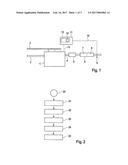
[0037] In FIG. 2 some process steps are shown that are implemented during the diagnosis of the oxides of nitrogen storage catalytic converter 7 according to one possible embodiment. The method starts with a step 20. In a step 21 the internal combustion engine 1 is operated such that the NH.sub.3 stored in the SCR catalytic converter 7 is released, which can be achieved by raising the temperature of the catalytic converter. Alternatively, the NH.sub.3 level can be passively lowered by a NO.sub.x reduction with simultaneous inhibition of the NH.sub.3 feed.
[0038] In a step 22 the release of the NH.sub.3 is ended. In a step 23 the internal combustion engine is operated with a lean fuel mixture. In a step 24 the NO.sub.x slip is determined. For this purpose, the NO.sub.x component in the flow of exhaust gas upstream of the catalytic converter box 6 is determined and the NO.sub.x concentration downstream of the catalytic converter box 6 is measured by means of the NO.sub.x sensor 9. The difference of said values gives the NO.sub.x slip.
[0039] In a step 25 the previously described adaptation is carried out by for example calculating a quality factor or the conversion efficiency of the oxides of nitrogen storage catalytic converter 8. Alternatively, the conversion efficiency can be used to diagnose the oxides of nitrogen storage catalytic converter 8.
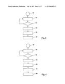
[0040] FIG. 3 shows some process steps during the performance of the diagnosis of a SCR catalytic converter. The method starts in a step 30. In a step 31 the oxides of nitrogen storage catalytic converter 8 is loaded with NO.sub.x. For this purpose, a suitable operating mode of the internal combustion engine 1 is selected, in particular the internal combustion engine 1 is operated with a lean fuel mixture. In a step 32 a check is made as to whether the storage catalytic converter 8 is fully loaded. For this purpose, it is measured by means of the NO.sub.x probe 9 whether NO.sub.x is contained in the flow of exhaust gas downstream of the catalytic converter box 6. If this is the case, then in a step 33 the mass of NO.sub.x in the flow of exhaust gas upstream of the catalytic converter box 6 is determined. This can be carried out by means of a suitable model. If there is a further NO.sub.x sensor upstream of the catalytic converter box 6, then said value can be determined particularly accurately by means of said sensor.
[0041] In a step 34 the difference between the mass of NO.sub.x upstream of the catalytic converter box 6 in the flow of exhaust gas and downstream of the catalytic converter box 6 is determined. In a step 35 the conversion efficiency of the SCR catalytic converter 7 is concluded from said difference.
[0042] FIG. 4 shows process steps of a further embodiment that is carried out during the diagnosis of the SCR catalytic converter 7. The method starts in a step 40. In a step 41 the oxides of nitrogen storage catalytic converter 8 is loaded with NO.sub.x. In a step 42 it is measured whether there is a NO.sub.x slip, i.e. the storage catalytic converter 8 is loaded. This is achieved by analyzing the signal of the NO.sub.x sensor 9.
[0043] In a step 43 the regeneration of the oxides of nitrogen storage catalytic converter 8, which would usually begin now, is suppressed because the oxides of nitrogen storage catalytic converter 8 is fully loaded.
[0044] In a step 44 a state is established in which a maximum NO.sub.x concentration upstream of the catalytic converter box 6 is such that the NO.sub.x would be completely converted in the case of an optimally working or a new SCR catalytic converter with sufficient stored NH.sub.3. In the case of a passive SCR catalytic converter 7 that is still converting sufficiently well, no NO.sub.x slip is now measured at the NO.sub.x sensor in the step 45.
[0045] The quality is now determined in a step 46. If the SCR catalytic converter 7 has aged and consequently no longer has the property of converting NO.sub.x sufficiently well, a slip measured in the step 45 is correspondingly assessed in the step 46 and the conversion efficiency is determined.
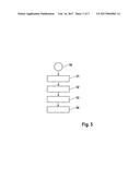
[0046] FIG. 5 shows some process steps during the diagnosis of the SCR catalytic converter 7, wherein NH.sub.3 values are used that are detected by means of the NO.sub.x sensor 9. The process starts in a step 50.
[0047] In a step 51 the amount of NO.sub.x in the flow of exhaust gas upstream of the catalytic converter box 6 is determined. This can either be measured by means of a further NO.sub.x sensor or calculated by means of a suitable NO.sub.x untreated mass model and an oxidation catalytic converter model. In a step 52, the mass of NH.sub.3 in the flow of exhaust gas downstream of the catalytic converter box 6 is determined by means of the NO.sub.x sensor 9.
[0048] In a step 53, NH.sub.3 desorption may be taken into account. This occurs as a result of NH.sub.3 being able to arise from the NO.sub.x stored in the oxides of nitrogen storage catalytic converter 8. The desorption can be determined by integrating the NH.sub.3 signal downstream of the NO.sub.x storage catalytic converter 8 until a defined time and adding the result to the NH.sub.3 storage capacity.
[0049] Alternatively, a graph of the NH.sub.3 signal can be calculated and fitted to the later profile in the region of the NH.sub.3 desorption. However, it can also be provided to operate the internal combustion engine 1 in the step 53 such that the NH.sub.3 desorption is suppressed. This is achieved by emptying the NO.sub.x storage catalytic converter 8 or releasing the NO.sub.x stored therein before the measurement of the NH.sub.3 signal in the step 52, for which purpose for example, a temperature increase before the measurement is the aim.
[0050] In a step 54 the NH.sub.3 slip is analyzed and the conversion efficiency of the SCR catalytic converter is determined depending on the result.
User Contributions:
Comment about this patent or add new information about this topic:
Images included with this patent application:
 |  |
 |  |
| Similar patent applications: | |
| Date | Title |
|---|---|
| 2016-08-18 | High-efficiency catalytic converters for treating exhaust gases |
| 2016-08-18 | Immobilized metathesis tungsten oxo alkylidene catalysts and use thereof in olefin metathesis |
| 2016-08-18 | Method for making anion exchange and chelant resins including aliphatic amino functional groups |
| 2016-08-18 | System and method for providing state information of an action figure |
| 2016-08-18 | Catalyst loading device and catalyst loading method |
| New patent applications in this class: | |
| Date | Title |
|---|---|
| 2022-09-22 | Electronic device |
| 2022-09-22 | Front-facing proximity detection using capacitive sensor |
| 2022-09-22 | Touch-control panel and touch-control display apparatus |
| 2022-09-22 | Sensing circuit with signal compensation |
| 2022-09-22 | Reduced-size interfaces for managing alerts |
| New patent applications from these inventors: | |
| Date | Title |
|---|---|
| 2014-08-28 | Method and control unit for reducing the power consumption in an electrical supply network |
| 2014-05-15 | Method and device for operating an internal combustion engine |
| 2013-11-28 | Method for determining a type of air-fuel mixture error |
| 2011-10-20 | Method and apparatus for the self-diagnosis of an exhaust gas probe |
| 2009-01-15 | Procedure for operating a particle sensor that is arranged downstream after a particle filter and device for implementing this procedure |