Patent application title: FAN CONTROL CIRCUIT AND AN ELECTRONIC DEVICE USING THE SAME
Inventors:
Lei Liu (Shenzhen, CN)
Lei Liu (Shenzhen, CN)
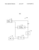
Guo-Yi Chen (Shenzhen, CN)
IPC8 Class: AF04D2700FI
USPC Class:
1 1
Class name:
Publication date: 2017-01-26
Patent application number: 20170022995
Abstract:
A fan control circuit set in an electronic device, the fan control
circuit includes a fan, a controller, a power supply, and a timer. The
fan operates normally when the fan receives a control signal and a
voltage. The controller outputs the control signal. The power supply
supplies power. The timer is coupled between the fan, the controller, and
the power supply. A first input of the timer is coupled to the controller
to receive the control signal. When a second input of the timer receives
a first signal from the power supply, the first input of the timer is
coupled to an output of the timer. When the second input of the timer
receives a second signal from the power supply, the second input of the
timer is disconnected from the output of the timer after a preset time.Claims:
1. A fan control circuit comprising: a fan configured to operate normally
in event the fan receives a control signal and power; a controller
configured to output the control signal; a power supply configured to
supply power; a timer coupled to the fan and the power supply, the timer
comprising a first input and a second input, the first input coupled to
the controller and configured to receive the control signal; wherein when
a second input of the timer receives a first signal from the power
supply, the first input of the timer is coupled to an output of the
timer; when the second input of the timer receives a second signal from
the power supply, the first input of the timer is disconnected from the
output of the timer after a preset time.
2. The fan control circuit as claim 1, wherein the controller is a baseboard management controller.
3. The fan control circuit as claim 1, wherein the control signal is a pulse-width modulation signal.
4. The fan control circuit as claim 1, wherein a first output of the power supply is coupled to a power terminal of the fan, a second output of the power supply is coupled to the second input of the timer.
5. The fan control circuit as claim 4, further comprising a voltage converter, an input of the voltage converter is coupled to the second output of the power supply, an output of the voltage converter is coupled to the power terminal of the fan, wherein when the electronic device is operating, the power supply outputs a first voltage which is at a high level to the voltage converter, the voltage converter converts the first voltage into a second voltage and outputs the second voltage to the power terminal of the fan, when the electronic device stops operating, the power supply outputs the second voltage to the fan through the first output.
6. An electronic device comprising a fan control circuit, the fan control circuit comprising: a fan operating normally when the fan receives a control signal and a voltage; a controller configured to output the control signal; a power supply configured to supply power; a timer coupled to the fan and the power supply, wherein a first input of the timer is coupled to the controller to receive the control signal, when a second input of the timer receives a first signal from the power supply, the first input of the timer is coupled to an output of the timer; when the second input of the timer receives a second signal from the power supply, the first input of the timer is disconnected from the output of the timer after a preset time.
7. The electronic device as claim 6, wherein the controller is a baseboard management controller.
8. The electronic device as claim 6, wherein the control signal is a pulse-width modulation signal.
9. The electronic device as claim 6, wherein a first output of the power supply is coupled to a power terminal of the fan, a second output of the power supply is coupled to the second input of the timer.
10. The electronic device as claim 9, further comprising a voltage converter, an input of the voltage converter is coupled to the second output of the power supply, an output of the voltage converter is coupled to the power terminal of the fan, wherein when the electronic device is operating, the power supply outputs a first voltage which is at a high level to the voltage converter, the voltage converter converts the first voltage into a second voltage and outputs the second voltage to the power terminal of the fan, when the electronic device stops operating, the power supply outputs the second voltage to the fan through the first output.
Description:
FIELD
[0001] The subject matter herein generally relates to an electronic device with a fan control circuit.
BACKGROUND
[0002] A power supply stops supplying power for fans when a server is shut down.
BRIEF DESCRIPTION OF THE DRAWING
[0003] Implementations of the present technology will now be described, by way of example only, with reference to the attached FIGURE.
[0004] The FIGURE is a block diagram of an embodiment of an electronic device with a fan control circuit.
DETAILED DESCRIPTION
[0005] Numerous specific details are set forth in order to provide a thorough understanding of the embodiments described herein. However, it will be understood by those of ordinary skill in the art that the embodiments described herein can be practiced without these specific details. In other instances, methods, procedures, and components have not been described in detail so as not to obscure the related relevant feature being described. Also, the description is not to be considered as limiting the scope of the embodiments described herein.
[0006] Several definitions that apply throughout this disclosure will now be presented.
[0007] The term "coupled" is defined as connected, whether directly or indirectly through intervening components, and is not necessarily limited to physical connections. The connection can be such that the objects are permanently connected or releasably connected. The term "comprising" when utilized, means "including, but not necessarily limited to"; it specifically indicates open-ended inclusion or membership in the so-described combination, group, series and the like.
[0008] The FIGURE shows an embodiment of a fan control circuit 100 applied in an electronic device 200. The fan control circuit 100 can comprise a fan 20, a baseboard management controller (BMC) 30, a timer 40, a power supply 50, and a voltage converter 60. The fan control circuit 100 can be set in a server.
[0009] The BMC 30 can comprise an output O1. The output O1 is configured to output a power wide management (PWM) signal to control the fan 20.
[0010] The fan 20 can comprise a control terminal C and a power terminal P. The control terminal C is configured to receive the PWM signal. The power terminal P is configured to receive a voltage. The fan operates normally when the fan receives the PWM signal and the voltage.
[0011] The timer 40 can comprise a first input I1 and a second input I2. The power supply 50 can comprise a first output O3 and a second output O4. The first input I1 of the timer 40 is coupled to the output O1 of the BMC 40 to receive the PWM signal. The second input I2 of the timer 40 is coupled to the second output O4 of the power supply 50. An output O2 of the timer 40 is coupled to the control terminal C of the fan 20 to transmit the PWM signal.
[0012] When the second input I2 is at a high level, the first input I1 of the timer 40 is coupled to the output O2 of the timer 40. When the second input I2 turns into a low level, a connection between the first input I1 and the output O2 would be disconnected after a preset time.
[0013] The first output O3 of the power supply 50 is coupled to an anode of a diode D. A cathode of the diode D is coupled to the power terminal P of the fan 20. The diode D is configured to protect the power supply 50.
[0014] An input I2 of the voltage converter 60 is coupled to the second output O4 of the power supply 50. An output O5 of the voltage converter 60 is coupled to the power terminal P of the fan 20 and the cathode of the diode D.
[0015] When the server is operating, the power supply outputs a first voltage through the second output O4. The first voltage is 12 volt (V) in this embodiment. The second input I2 of the timer 40 is at a high level and the timer 40 transmits the PWM signal from the BMC 30 to the control terminal C of the fan 20. The input 13 of the voltage converter 60 receives the first voltage. The voltage converter 60 converts the first voltage into a second voltage. The voltage converter outputs the second voltage to the power terminal P of the fan 20 through the output O5.
[0016] In the embodiment, the second voltage is 5 V. The fan 20 operates normally when the fan 20 receives the PWM signal and the second voltage synchronously.
[0017] When the server stops operating, the BMC 30 outputs a constant PWM signal. The power supply 50 stops outputting the first voltage through the second output O4, and starts outputting a third voltage through the first output O3. In the embodiment the third voltage is an auxiliary voltage of 5 V. The second input I2 of the timer 40 is at a low level. The timer 40 starts timing and continues to transmit the PWM signal to the control terminal C of the fan 20 in a preset time. The fan 20 receives the PWM signal and the second voltage synchronously. The timer 40 stops transmitting the PWM signal to the fan 20 after the preset time.
[0018] In other embodiments, when the server is operating, the power supply 50 outputs the first voltage through the second output O4 and outputs the third voltage to the power terminal P of the fan 20 through the first output O3 at the same time.
[0019] While the disclosure has been described by way of example and in terms of the embodiment, it is to be understood that the disclosure is not limited thereto. On the contrary, it is intended to cover various modifications and similar arrangements as would be apparent to those skilled in the art. Therefore, the range of the appended claims should be accorded the broadest interpretation so as to encompass all such modifications and similar arrangements.
User Contributions:
Comment about this patent or add new information about this topic:


