Patent application title: BRAKE RELEASE MECHANISM FOR SURGICAL TABLE
Inventors:
Ben Hertz (Acton, MA, US)
IPC8 Class: AA61G102FI
USPC Class:
1 1
Class name:
Publication date: 2016-10-13
Patent application number: 20160296388
Abstract:
A surgical patient support includes a foundation frame, a support top,
and a brake system. The foundation frame includes a first column and a
second column The support top is coupled to the first column and the
second column for rotation about a top axis extending along the length of
the support top.Claims:
1. A patient support apparatus comprising a caster including a stem, a
wheel coupled to the stem to rotate about an wheel axis relative to the
stem, and a braking element movable from a disengaged position allowing
rotation of the wheel relative to the stem to an engaged position
blocking the wheel from rotation relative to the stem, a brake drive
including a mount and a linear actuator coupled to the mount, the linear
actuator configured to move from a retracted position to an extended
position relative to the mount, and a linkage including a shaft coupled
to the braking element to move the braking element between the disengaged
and the engaged positions and coupled to the linear actuator to be moved
by the linear actuator relative to the mount, a release assembly coupled
between the shaft and the linear actuator to selectively couple the shaft
to the linear actuator, a disengaging-bias spring coupled to the shaft to
move the shaft so that the braking element is moved from the engaged
position to the disengaged position when the shaft is decoupled from the
linear actuator, and a locator spring coupled to the shaft to resist the
disengaging-bias spring so that the shaft moves to a preselected position
when decoupled from the linear actuator.
2. The patient support apparatus of claim 1, wherein the locator spring is arranged between a locator collar coupled to the shaft and a first side of the mount.
3. The patient support apparatus of claim 2, wherein the disengaging-bias spring is arranged between a disengaging-bias collar coupled to the shaft and a second side of the mount, opposite the first side of the mount.
4. The patient support apparatus of claim 1, wherein the linkage includes a pivot connector coupled to the shaft for movement about a connector axis and coupled to the braking element of the caster to convert linear motion from the linear actuator into rotating motion applied to the braking element.
5. The patient support apparatus of claim 1, wherein the release assembly includes a plate and a handle coupled to the plate, the plate being movable from a first position in which the plate couples the shaft to the linear actuator for movement therewith to a second position in which the plate releases the shaft from the linear actuator for motion independent of the shaft, and the plate moves from the first position to the second position in response to a user moving the handle.
6. The patient support apparatus of claim 5, wherein the plate is biased toward the first position.
7. The patient support apparatus of claim 5, wherein the plate is coupled to the linear actuator to pivot about a plate axis relative to the linear actuator.
8. The patient support apparatus of claim 5, wherein the plate is formed to include a slot that receives a pin coupled to the shaft.
9. The patient support apparatus of claim 5, wherein the plate is formed to include a hole through which the shaft extends, the hole having a first section sized to engage the shaft and a second section sized to allow the shaft to slide through the plate.
10. A patient support apparatus comprising a pair of casters each including a stem, a wheel coupled to the stem to rotate about an wheel axis relative to the stem, and a braking element movable from a disengaged position allowing the wheel to rotate relative to the stem to an engaged position blocking the wheel from rotation relative to the stem, a brake drive including a mount and an actuator coupled to the mount, the actuator configured to move from a first position to a second position relative to the mount, and a linkage coupled to the braking element of each of the casters, the linkage configured to selectively couple the actuator of the brake drive to the braking element to transfer motion of the actuator to the braking element and to selectively decouple the braking element from the actuator to allow a disengaging-bias spring included in the linkage to move the braking elements from the engaged position to the disengaged position, wherein the linkage further includes a locator spring that resists the disengaging-bias spring so that the braking elements are properly located in the disengaged position when the braking element is decoupled from the actuator.
11. The patient support apparatus of claim 10, wherein the linkage includes a shaft that is selectively coupled to the actuator and the locator spring is arranged between a locator collar coupled to the shaft and a first side of the mount.
12. The patient support apparatus of claim 11, wherein the disengaging-bias spring is arranged between a disengaging-bias collar coupled to the shaft and a second side of the mount, opposite the first side of the mount.
13. The patient support apparatus of claim 10, wherein the linkage includes an actuation member coupled to the actuator for movement therewith, a rod assembly coupled to the braking elements of the casters, and a plate coupled to the actuation member and to the rod assembly.
14. The patient support apparatus of claim 13, wherein the plate is coupled to the actuation member to pivot relative to the actuation member about a plate axis.
15. The patient support apparatus of claim 13, wherein the rod assembly includes a shaft slidable along a shaft axis, a first pivot connector coupled to the shaft and to one of the braking elements included in one of the casters, and a second pivot connector coupled to the shaft and to the other of the braking elements included in the other of the casters.
16. The patient support apparatus of claim 15, wherein the locator spring receives the shaft and is arranged between a locator collar coupled to the shaft and a first side of the mount.
17. The patient support apparatus of claim 16, wherein the disengaging-bias spring receives the shaft and is arranged between a disengaging-bias collar coupled to the shaft and a second side of the mount, opposite the first side of the mount.
18. The patient support apparatus of claim 15, wherein the rod assembly further includes a pin extending outwardly from the shaft and received in a slot formed in the plate.
19. The patient support apparatus of claim 15, wherein the shaft extends through a hole formed in the plate.
20. The patient support apparatus of claim 15, wherein the actuation member is a slider coupled to the shaft to slide along the shaft axis relative to the shaft.
Description:
CROSS-REFERENCE TO RELATED APPLICATIONS
[0001] The present application claims the benefit, under 35 U.S.C. .sctn.119(e), of U.S. Provisional Application No. 62/145,270, which was filed Apr. 9, 2015, and which is hereby incorporated by reference herein in its entirety.
BACKGROUND
[0002] The present disclosure relates to patient support apparatuses such as surgical tables. More particularly, the present disclosure relates to wheeled surgical tables having brakes. The present disclosure may also be applicable to other types of patient support apparatuses such as hospital beds, home care beds, x-ray tables, therapy supports, wheel chairs, and the like.
[0003] Sometimes, surgical tables have powered brakes. In such designs, redundant non-powered manual brake controls may be desired to allow the brakes to be disengaged in the event of a power outage.
SUMMARY
[0004] The present application discloses one or more of the features recited in the appended claims and/or the following features which, alone or in any combination, may comprise patentable subject matter:
[0005] According to the present disclosure, a patient support apparatus may include a powered brake system. The powered brake system may include a caster, a brake drive, and a linkage. The caster may include a stem, a wheel coupled to the stem to rotate about an wheel axis relative to the stem, and a braking element movable from a disengaged position allowing rotation of the wheel relative to the stem to an engaged position blocking the wheel from rotation relative to the stem. The brake drive may include a mount and a linear actuator coupled to the mount. The linear actuator may be configured to move from a retracted position to an extended position relative to the mount. The linkage may interconnect the brake drive with the caster.
[0006] In some embodiments, the linkage may include a shaft, a release assembly, a disengaging-bias spring, and a locator spring. The shaft may be coupled to the braking element to move the braking element between the disengaged and the engaged positions and may be coupled to the linear actuator to be moved by the linear actuator relative to the mount. The release assembly may be coupled between the shaft and the linear actuator to selectively couple the shaft to the linear actuator. The disengaging-bias spring may be coupled to the shaft to move the shaft so that the braking element is moved from the engaged position to the disengaged position when the shaft is decoupled from the linear actuator. The locator spring may be coupled to the shaft to resist the disengaging-bias spring so that the shaft moves to a preselected position when decoupled from the linear actuator.
[0007] In some embodiments, the locator spring may be arranged between a locator collar coupled to the shaft and a first side of the mount. The disengaging-bias spring may be arranged between a disengaging-bias collar coupled to the shaft and a second side of the mount, opposite the first side of the mount.
[0008] In some embodiments, the linkage may include a pivot connector coupled to the shaft for movement about a connector axis. The pivot connector may also be coupled to the braking element of the caster to convert linear motion from the linear actuator into rotating motion applied to the braking element.
[0009] In some embodiments, the release assembly may include a plate and a handle coupled to the plate. The plate may be movable from a first position in which the plate couples the shaft to the linear actuator for movement therewith to a second position in which the plate releases the shaft from the linear actuator for motion independent of the shaft. The plate may move from the first position to the second position in response to a user moving the handle. The plate may be biased toward the first position. The plate may be coupled to the linear actuator to pivot about a plate axis relative to the linear actuator. The plate may be formed to include a slot that receives a pin coupled to the shaft.
[0010] In some embodiments, the plate may be formed to include a hole through which the shaft extends. The hole may have a first section sized to engage the shaft and a second section sized to allow the shaft to slide through the plate.
[0011] According to another aspect of the present disclosure, a patient support apparatus includes a brake system. The brake system may include a pair of casters, a brake drive, and a linkage. The pair of casters may each include a stem, a wheel coupled to the stem to rotate about an wheel axis relative to the stem, and a braking element movable from a disengaged position allowing the wheel to rotate relative to the stem to an engaged position blocking the wheel from rotation relative to the stem. The brake drive may include a mount and an actuator coupled to the mount. The actuator may be configured to move from a first position to a second position relative to the mount. The linkage may be coupled to the braking element of each of the casters.
[0012] In some embodiments, the linkage may be configured to selectively couple the actuator of the brake drive to the braking element to transfer motion of the actuator to the braking element and to selectively decouple the braking element from the actuator to allow a disengaging-bias spring included in the linkage to move the braking elements from the engaged position to the disengaged position. The linkage may further include a locator spring that resists the disengaging-bias spring so that the braking elements are properly located in the disengaged position when the braking element is decoupled from the actuator.
[0013] In some embodiments, the linkage may include a shaft that is selectively coupled to the actuator. The locator spring may be arranged between a locator collar coupled to the shaft and a first side of the mount. The disengaging-bias spring may be arranged between a disengaging-bias collar coupled to the shaft and a second side of the mount, opposite the first side of the mount.
[0014] In some embodiments, the linkage may include an actuation member coupled to the actuator for movement therewith, a rod assembly coupled to the braking elements of the casters, and a plate coupled to the actuation member and to the rod assembly. The plate may be coupled to the actuation member to pivot relative to the actuation member about a plate axis.
[0015] In some embodiments, the rod assembly may include a shaft slidable along a shaft axis, a first pivot connector coupled to the shaft and to one of the braking elements included in one of the casters, and a second pivot connector coupled to the shaft and to the other of the braking elements included in the other of the casters. The locator spring may receive the shaft and is arranged between a locator collar coupled to the shaft and a first side of the mount. The disengaging-bias spring may receive the shaft and may be arranged between a disengaging-bias collar coupled to the shaft and a second side of the mount, opposite the first side of the mount.
[0016] In some embodiments, the rod assembly further includes a pin extending outwardly from the shaft and received in a slot formed in the plate. The shaft may extend through a hole formed in the plate. The actuation member may be a slider coupled to the shaft to slide along the shaft axis relative to the shaft
[0017] Additional features, which alone or in combination with any other feature(s), such as those listed above and those listed in the claims, may comprise patentable subject matter and will become apparent to those skilled in the art upon consideration of the following detailed description of various embodiments exemplifying the best mode of carrying out the embodiments as presently perceived.
BRIEF DESCRIPTION OF THE DRAWINGS
[0018] The detailed description particularly refers to the accompanying figures, in which:
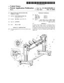
[0019] FIG. 1 is a perspective view of a patient support apparatus having a powered brake system with a manual release;
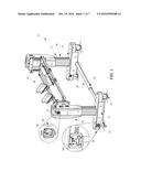
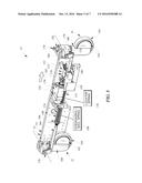
[0020] FIG. 2 is a perspective view of one brake mechanism included in the brake system used in the patient support apparatus of FIG. 1;
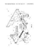
[0021] FIG. 3 is an exploded view of the brake mechanism of FIG. 2 showing that the brake mechanism includes a disengaging-bias spring configured to disengage brake elements when the manual release is pulled and a locator spring configured to resist the disengaging bias spring and properly locate the components of the brake mechanism when manually released;
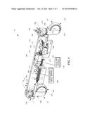
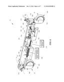
[0022] FIG. 4 is a perspective view of brake mechanism of FIGS. 2 and 3 showing the brake mechanism in an unbraked configuration ready for powered movement to the braked configuration as shown in FIG. 5;
[0023] FIG. 5 is a perspective view similar to FIG. 4 showing the brake mechanism moved to the braked configuration by powered operation of the brake system;
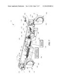
[0024] FIG. 6 is a perspective view similar to FIG. 4 showing the brake mechanism in the braked configuration as a user pulls a release handle included in the brake mechanism; and
[0025] FIG. 7 is a perspective view similar to FIG. 4 showing the brake mechanism returned to the unbraked configuration by a disengaging-bias spring and a locator spring in response to the release handle being pulled.
DETAILED DESCRIPTION
[0026] A patient support apparatus 10 for supporting a patient during surgery is shown in FIG. 1. The patient support apparatus 10 illustratively includes a foundation frame 12 and a patient support top 14. The foundation frame 12 rests on a floor 16 and is configured to suspend the support top 14 in a number of different positions above the floor 16. Thus, a patient undergoing surgery can be moved with the support top 14 to a number of different positions and orientations depending on the particular surgical operation to be performed on the patient.
[0027] The foundation frame 12 includes a first column 24, a second column 26, an extension 28, and a control system 30 as shown in FIG. 1. Each column 24, 26 of the patient support apparatus 10 includes a pair of casters 33, 35 that engage the floor 16 as shown in FIG. 1. All of the casters 33, 35 are selectively braked or unbraked by a powered brake system 50 to allow the patient support apparatus 10 to roll along the floor 16 to different surgery or storage rooms within a healthcare facility.
[0028] The powered brake system 50 includes a manual release mechanism as further described below so that the support apparatus 10 may be freed for movement in case of a power failure as suggested in FIG. 1. The manual release mechanism includes a disengaging-bias spring 198 that biases the brake system 50 toward an unbraked condition when manually released as shown in FIG. 2. The release mechanism also includes a locator spring 110 that resists the disengaging-bias spring 198 to prevent overtravel of the brake system 50 past a predetermined unbraked condition as shown in FIG. 2.
[0029] Powered operation of the brake system 50 is illustratively controlled by a switch box 62, which includes a housing 84 and a rotary switch 86 received in the housing 84 as shown in FIG. 1. Rotary switch 86 is configured to move between a first position, wherein the brake system 50 is braked, and a second position, wherein the brake system 50 is unbraked.
[0030] When the brake system 50 is unbraked, the casters 33, 35 are free to roll along the floor 16 in different directions. When the brake system is braked, the casters 33, 35 are blocked from rolling along the floor 16 and are held in a single direction. In some embodiments, the rotary switch is movable to a third position to initiate a brake reset sequence to reset the brake system 50 after the brake system 50 has been manually released as further described below. In other embodiments, one or more membrane switches, pivot switches, or other suitable user inputs may be used to control the brake system 50.
[0031] The brake system 50 illustratively includes a head end brake mechanism 51 and a foot-end brake mechanism 52 as suggested in FIG. 1. Each brake mechanism 51, 52 is substantially similar; and, for ease of description, only mechanism 51 is further described herein. However, the following description is equally applicable to brake mechanism 52. Brake mechanism 51 illustratively includes a brake drive 150, a pair of casters 33, 35, and a releasable linkage 152 as shown FIGS. 2 and 3. The brake drive 150 is configured to drive the braking system 50 between a braked configuration and an unbraked configuration in response to a user turning rotary switch 86. The releasable linkage 152 is coupled between the brake drive 150 and the casters 33, 35. The releasable linkage is configured to allow a user to manually free the braking system 50 to move to a released-and-unbraked configuration. The manually achieved released-and-unbraked configuration allows a user to move the patient support apparatus 10 in case of a power failure, an emergency, or an equipment failure.
[0032] The brake drive 150 includes a mount block 154, a linear actuator 156, and a slider 158 as shown in FIG. 3. The mount block 154 is coupled to a lower plate 53. Mount block 154 supports the linear actuator 156 and the releasable linkage 152. The linear actuator 156 is coupled to the mount block 154 by a bolt 159 and is configured to extend and retract in response to a user input to the switch box 62. The slider 158 is coupled to the releasable linkage 152 and to the linear actuator 156 by a bolt 155.
[0033] The casters 33, 35 each include a stem 160, a hub 162, and a wheel 164 as shown in FIG. 30. The stem 160 is coupled to the lower plate 53. The hub 162 and the wheel 164 are coupled to the stem 160 for pivotable movement about a vertical axis 166 so that the caster can change direction relative to the base 31. The wheel 64 is coupled to the hub 162 for rotation about a horizontal axis 168 so that the casters 33, 35 can roll. In the illustrative embodiment, the casters 33, 35 are substantially similar to casters 33, 35 and are each of a type described in U.S. Pat. No. 7,506,404 available from TENTE USA.
[0034] Each of the four casters 33, 35 also include a braking element 170 housed inside stem 160 as shown in FIG. 29. The braking element 170 is movable between a disengaged and an engaged configuration. In the disengaged configuration, the braking element 170 allows pivoting of the hub 162 and the wheel 164 about the vertical axis 166 and allows rotation of the wheel 164 about the horizontal axis 168. In the engaged configuration, the braking element 170 blocks pivoting of the hub 162 and the wheel 164 about the vertical axis 166 and blocks rotation of the wheel 164 about the horizontal axis 168, thereby completely immobilizing the casters 33, 35. Unlike the prior art in which only one caster is completely immobilized to provide a steer mode or to resist some movement of a patient support in a brake mode, when the casters 33, 35 of the braking system 50 are driven to the braked configuration, the braking elements 170 of all four casters 33, 35 are engaged to immobilize the casters 33, 35. The immobilization of the casters 33, 35 prevents movement of the patient support apparatus 10 during surgery. To move the braking elements 170 of the casters 33, 35 between the disengaged and the engaged configuration, a dowel 173 extending into the stem 160 is rotated. The dowel 173 has at least one flat side and is hexagonal in the illustrative embodiment.
[0035] The releasable linkage 152 is configured to convert linear motion from the brake drive 150 into rotation of the dowels 173 so that the braking system 50 is driven between the unbraked and the braked configuration as suggested in FIGS. 31 and 32. The releasable linkage 152 is also configured to manually release the casters 33, 35 from the brake drive 150 and to move the braking elements 170 of the casters 33, 35 from the engaged configuration to the disengaged configuration so that the braking system is in the released-and-unbraked configuration when a user manually releases the linkage 152 as suggested in FIGS. 33 and 34.
[0036] The releasable linkage 152 includes a release assembly 172, a rod assembly 174, and a pair of pivot connectors 176 connected at opposing ends of the rod assembly 174 as shown in FIG. 30. The release assembly 172 is coupled to the slider 158 of the brake drive 150 and transfers motion of the brake drive 150 to the rod assembly 174 as shown in FIG. 32. The rod assembly 174 extends through the mount block 154 and along the base 31. The pivot connectors 176 couple the rod assembly 174 to the dowels 173 and are configured to convert linear motion from the linear actuator 156 to rotating motion so that the dowels 173 are turned and the braking elements 170 of the casters 33, 35 are moved between the disengaged and the engaged configurations.
[0037] The release assembly 172 is configured to selectively transfer motion of the brake drive 150 to the rod assembly 174. The release assembly 172 includes a handle 178, a link member 179, and a plate 180. The handle 178 is configured to be pulled by a user to disconnect the brake drive 150 and the rod assembly 174 so that the brake system 50 is moved to the unbraked configuration. The link member 179 extends between the handle 178 and the plate 180. The plate 180 is coupled to the slider 158 and moves between a first position transferring motion of the brake drive 150 to the rod assembly 174 and a second position releasing the brake drive 150 from the rod assembly 174.
[0038] The rod assembly 174 includes a shaft 194, a disengaging-bias collar 196, and a disengaging-bias spring 198 as shown in FIG. 30. The shaft 194 extends through the mount block 154 along the length of the base 31. The disengaging-bias collar 196 extends outwardly from the shaft 194 and is spaced apart from the mount block 154. The disengaging-bias spring 198 is configured to bias the releasable linkage 152 so that the braking system 50 is moved from the braked configuration to the unbraked configuration when the handle 178 is pulled out and the linear actuator 156 of the brake drive 150 is extended.
[0039] In the illustrative embodiment, the rod assembly 174 of the linkage 152 also includes a locator spring 110 adapted to resist the disengaging-bias spring 198 so that the shaft 194 moves to a preselected position when decoupled from the linear actuator 156 as suggested in FIG. 7. The locator spring 110 is arranged between a locator collar 112 coupled to the shaft 194 and a first side of the mount 154. Correspondingly, the disengaging-bias spring 198 is arranged between the disengaging-bias collar 196, which is coupled to the shaft 194, and a second side of the mount 154.
[0040] The exemplary disengaging-bias spring 198 and the locator spring 110 are compression coil springs that receive the shaft 154 as shown in FIG. 2. However, in other embodiments, the springs 198, 110 may be provided by wave springs, leaf springs, gas springs, or other suitable biasing devices.
[0041] The handle 178 includes a grip 182 and a rod 184 as shown in FIG. 29. The grip 182 is a T-shape grip configured to be pulled by a user. The rod 184 extends from the grip 182 to the link member 179.
[0042] The link member 179 is coupled to the block 158 for pivotable movement about a link axis 181 as shown in FIG. 29. The link member 179 is also coupled to the plate 180 so that the plate 180 moves between the first and second positions when the link member 179 pivots. The link member 179 is formed to include a rod slot 188 sized to coupled to the rod 184 of the handle 178 by a pin 118 so that the rod 184 can slide along the plate 180 when a user pulls on the grip 182.
[0043] The plate 180 is received in a slot 195 formed in the slider 158 and is blocked from being removed by a bolt 199. The plate 190 configured to slide between the first position and the second position when the link member 179 pivots. The plate 180 is formed to include a hole 192 with a first section 191 sized to engage the shaft 194 of the rod assembly 174 and a second section 193 sized to allow the shaft 914 of the rod assembly 174 to slide past the plate 180. The plate 180 is biased to the first position by a spring 185.
[0044] In powered operation, the braking system 50 is in the unbraked configuration when the linear actuator 156 is in the retracted position as shown in FIG. 31. In response to a user input to rotary switch 86, the linear actuator 156 is extended as shown in FIG. 32. When the linear actuator 156 is extended, the releasable linkage 152 converts the linear motion of the actuator 156 to rotation of the dowels 173 about 30 degrees so that the braking elements 170 are engaged and the casters 33, 35 are moved to the braked configuration. The braking system 50 may be returned to the unbraked configuration by a user operating the remote pendant 60 to retract the linear actuator 156.
[0045] To manually release the casters 33, 35 from the brake drive 150 when the brake system is in the braked configuration, a user pulls the grip 182 out as suggested in FIG. 33. In response to the grip 182 being pulled out, the plate 180 pivots about the axis 183 so that the plate 180 is moved to the second position and the shaft 194 of the releasable linkage 152 is free to move relative to the plate 180 and the brake drive 150. When the linkage 152 is free to move relative to the brake drive 150, the biasing disengaging-bias spring 198 moves the shaft 194 of the linkage 152 as shown in FIG. 34 so that the braking elements 170 of the casters 33, 35 are disengaged and the braking system 50 is moved to the released-and-unbraked configuration. The releasable linkage 152 remains free to move relative to the brake drive 150 until the linear actuator 156 is retracted so that the grip 182 is pulled back in, thereby linking the brake drive 150 and the releasable linkage 152 so that the braking system 50 is in the unbraked configuration as shown in FIG. 31.
[0046] The foregoing description of various embodiments and principles of the disclosure have been presented for the purposes of illustration and description. It is not intended to be exhaustive or to limit the disclosure to the precise forms disclosed. Many alternatives, modifications and variations will be apparent to those skilled in the art. Moreover, although multiple inventive aspects and principles have been presented, these need not be utilized in combination, and various combinations of inventive aspects and principles are possible in light of the various embodiments provided above. Accordingly, the above description is intended to embrace all possible alternatives, modifications, aspects, combinations, principles, and variations that have been discussed or suggested herein, as well as all others that fall within the principles, spirit and broad scope of the various possible inventions disclosed herein and defined by the claims.
User Contributions:
Comment about this patent or add new information about this topic:
Images included with this patent application:
 |  |
 |  |
 |  |
 |  |
| New patent applications in this class: | |
| Date | Title |
|---|---|
| 2022-09-22 | Electronic device |
| 2022-09-22 | Front-facing proximity detection using capacitive sensor |
| 2022-09-22 | Touch-control panel and touch-control display apparatus |
| 2022-09-22 | Sensing circuit with signal compensation |
| 2022-09-22 | Reduced-size interfaces for managing alerts |
| New patent applications from these inventors: | |
| Date | Title |
|---|---|
| 2021-11-18 | Surgical patient support for lateral-to-prone patient positioning |
| 2019-10-17 | Surgical patient support for accommodating lateral-to-prone patient positioning |
| 2017-05-18 | Person support apparatuses for subject repositioning |
| 2017-05-18 | Person support systems with cooling features |
| 2016-12-29 | Protective dressing with reusable phase-change material cooling insert |