Patent application title: METHOD OF CONTROLLING MOTOR OF FOOD MIXER, BASE FOR FOOD MIXER
Inventors:
Wen Ching Lee (Taichung City, TW)
Wen Ching Lee (Taichung City, TW)
IPC8 Class: AA47J43046FI
USPC Class:
1 1
Class name:
Publication date: 2016-10-13
Patent application number: 20160296072
Abstract:
A base for a food mixer includes a body in which a motor is mounted. The
base further includes a control unit having a first touch control panel
and a processor. The first touch control panel is mounted to a first side
of the body. The first touch control panel includes a sliding section. A
finger of a user is adapted to slide from an end towards the other end of
the sliding section, producing a sliding signal indicative of a sliding
distance and a sliding direction of the finger of the user. The processor
is in direct or indirect electrical connection with the motor and the
first touch control panel. The processor receives the sliding signal and
includes a motor control program. The processor changes a speed of the
motor according to the sliding signal due to sliding of the finger of the
user alone the sliding section.Claims:
1. A method of controlling a motor of a food mixer, the food mixer
including a touch control panel, the method comprising: detecting a
contact point with a touch sensitive section of the touch control panel,
the contact point produces by a finger of a user; contacting and sliding
the contact point on the touch sensitive section of the touch control
panel; and changing a speed of the motor according to a sliding distance
and a sliding direction on the touch sensitive section of the touch
control panel.
2. The method of claim 1, wherein the touch sensitive section having a first end and a second end, the gradually acceleration of the motor representative for the sliding from the first end of the touch sensitive section to the second of the touch sensitive section.
3. The method of claim 2, wherein the gradually deceleration of the motor representative for the sliding from the second end of the touch sensitive section to the first of the touch sensitive section.
4. The method of claim 2, wherein the lowest speed or the stop of the motor representative for the sliding at the first end.
5. The method of claim 2, wherein the fastest speed of the motor representative for the sliding at the second end.
6. A base for a food mixer, the base comprising: a body; a motor mounted in the body; a bulge extending a surface of the body; and a control unit including a first touch control panel and a processor, the first touch control panel including a touch sensitive section, the first touch control panel connected to the bulge, the processor connected to the first touch control panel and the motor, the first touch control panel being responsive to a finger of a user sliding along the touch sensitive portion of the sliding section to produce a sliding signal indicative of a sliding distance and a sliding direction of the finger of the user, the processor controlling a speed of the motor according to the sliding signal.
7. The base for a food mixer as claimed in claim 6, wherein the base includes a top side, the base further comprising a second touch control panel mounted on the top side of the base, the second touch control panel electrically connected to the control unit, the second touch control panel adapted to be touched by the finger of the user to control on/off of the control unit.
Description:
[0001] This U.S. continuation Patent Application claims priority from
commonly-assigned U.S. patent application Ser. No. 13/621,900, filed Sep.
18, 2012, which is hereby incorporated by reference herein in its
entirety.
BACKGROUND OF THE INVENTION
[0002] 1. Field of the Invention
[0003] The present invention relates to a rood mixer and, more particularly, to a base for a food mixer.
[0004] 2. Description of Related Art
[0005] A food mixer generally includes a container and a base. A cutter is mounted in a bottom of the container. A motor is mounted in the motor and is electrically connected to the cutter. A touch control panel is provided on a face of the base, allowing a user to control the speed or rotation mode of the motor by touching the touch control panel. However, the user has to repeatedly touch the touch control panel for increasing or reducing the speed of the motor. The speed of the motor is either too fast or too slow during operation, leading to inconvenience to use.
BRIEF SUMMARY OF THE INVENTION
[0006] To overcome the disadvantages of the prior art, the present invention provides a base for a food mixer. The base includes a body in which a motor is mounted. The base further includes a control unit having a first touch control panel and a processor. The first touch control panel is mounted to a first side of the body. The first touch control panel includes a sliding section. A finger of a user is adapted to slide from an end towards the other end of the sliding section, producing a sliding signal indicative of a sliding distance and a sliding direction of the finger of the user. The processor is in direct or indirect electrical connection with the motor and the first touch control panel. The processor receives the sliding signal and includes a motor control program. The processor changes a speed of the motor according to the sliding signal due to sliding of the finger of the user along the sliding section.
[0007] Preferably, a second touch control panel is mounted in a top side of the base and is electrically connected to the control unit. The second touch control panel is adapted to be touched by the finger of the user to control on/off of the control unit.
[0008] Preferably, a groove is defined in a second side of the base opposite to the first side of the base. A power connector is mounted in the groove.
[0009] Preferably, the groove includes top and bottom walls and a lateral wall extending between the top and bottom walls. The lateral wall includes a through-hole in communication with an interior of the base. The power connector includes a power cord and a plug. The power cord extends through the through-hole and has an end connected to the plug. Two columns are mounted in the groove, with each column having an upper end connected to the top wall and a lower end connected to the bottom wall, with the two columns spaced from each other.
[0010] Preferably, a bulge extends upward and outward from the first side of the base.
[0011] Preferably, the bulge includes a chamber having an opening in a top of the bulge, with the first touch control panel received in the opening.
[0012] The present invention will become clearer in light of the following detailed description of illustrative embodiments of this invention described in connection with the drawings.
BRIEF DESCRIPTION OF THE DRAWINGS
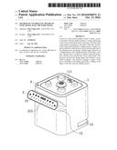
[0013] FIG. 1 shows a perspective view of a food mixer according to the present invention.
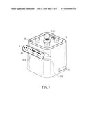
[0014] FIG. 2 shows an exploded, perspective view of the food mixer of FIG. 1.
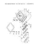
[0015] FIG. 3 shows a rear view of the food mixer of FIG. 1.
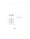
[0016] FIG. 4 shows a schematic block diagram illustrating electrical connection of some components of the food mixer of FIG. 1.
DETAILED DESCRIPTION OF THE PREFERRED EMBODIMENTS
[0017] With reference to FIGS. 1 and 4, a base A for a food mixer according to the present invention includes a body 1 in which a motor 11 is mounted. A driving member III is connected to a shall of the motor 11 and is exposed on a top side of the base 1. The driving member 11 is adapted to couple with and drive a cutter in a container of the food mixer, which can be appreciated by one skilled in the art.
[0018] With reference to FIG. 2, a bulge 12 extends upward and outward from a first side of the base 1. Preferably, the bulge 12 includes a chamber 121 having an opening 122 in a top of the bulge 12 for receiving a control unit 2. Since the bulge 12 extends upward and outward, the top of the bulge 12 faces the eyes of a user, allowing easy control by the user.
[0019] With reference to FIG. 3, the base 1 further includes a second side opposite to the first side. A groove 13 is defined in the second side, and a power connector 14 is mounted in the groove 13. The groove 13 includes top and bottom walls and a lateral wall extending between the top and bottom walls. The lateral wall includes a through-hole 131 in communication with an interior of the base I. The power connector 14 includes a power cord 141 and a plug 142. The power cord 141 extends through the through-hole 131 and has an end connected to the plug 142. Two columns 132 are mounted in the groove 13, with each column 132 having an upper end connected to the top wall and a lower end connected to the bottom wall, with the two columns 132 spaced from each other. The power cord 141 and the plug 142 can he received in the groove 13, avoiding exposure of the power connector 14 and, thus, allowing easy storage of the base A. The power cord 141 can be wound around the columns 132, avoiding entangling of the power cord 141 received in the groove 13.
[0020] With reference to FIGS. 1 and 2, the control unit 2 includes a first touch control panel 21 and a processor 22. The first touch control panel 12 is mounted to the top of the bulge 12. The first touch control panel 21 includes a sliding section 215 having two ends. A finger of the user can slide from one of the two ends towards the other end of the sliding section 215, producing a sliding signal indicative of a sliding distance and a sliding direction of the finger of the user.
[0021] The control unit 2 further includes an LED circuit hoard 211, a light-transmission frame 212, a touch control circuit hoard 213, and a shield 214 that are received in the chamber 121 in sequence. The patterns on the first touch control panel 21 transmit light to allow easy operation by the user. The operation, connection, and functions of the components received in the chamber 121 can be appreciated by one having ordinary skill in the art.
[0022] With reference to FIGS. 1 and 4, the processor 22 is in direct or indirect electrical connection with the motor 11 and the first touch control panel 21. The processor 22 receives the sliding signal. The processor 22 includes a motor control program. When the finger of the user slides along the sliding section 215, the processor 22 changes the speed of the motor 22 according to the sliding signal.
[0023] As an example, when the finger of the user touches the sliding section 215 and slides rightwards, the speed of the motor 11 gradually increases under control by the processor 22. When the finger reaches the right end of the sliding section 215, the speed of the motor 11 is the fastest. When the finger of the user touches the sliding section 215 and slides leftwards, the speed of the motor 11 gradually decreases under control by the processor 22. The motor 11 stops when the finger reaches the left end of the sliding section 215. Thus, operation of the food mixer is easy to the user.
[0024] With reference to FIGS. 1 and 2, a second touch control panel 3 is mounted on the top side of the base 1. As can be seen from FIG. 2, the top side of the base 1 includes a recessed portion 15 in which a waterproof member 31, an LED circuit hoard 32, a light-transmission frame 33, a touch control circuit board 34, and a shield 35 are received in sequence. The operation, connection, and functions of the components received in the recessed portion 15 can be appreciated by one having ordinary skill in the art.
[0025] The second touch control panel 3 is electrically connected to the control unit 2. The user can touch the second touch control panel 3 to control on/off of the control unit 2.
[0026] Although specific embodiments have been illustrated and described, numerous modifications and variations are still possible without departing from the essence of the invention. The scope of the invention is limited by the accompanying claims.
User Contributions:
Comment about this patent or add new information about this topic:
Images included with this patent application:
 |  |
 |  |
 |
| New patent applications in this class: | |
| Date | Title |
|---|---|
| 2022-09-22 | Electronic device |
| 2022-09-22 | Front-facing proximity detection using capacitive sensor |
| 2022-09-22 | Touch-control panel and touch-control display apparatus |
| 2022-09-22 | Sensing circuit with signal compensation |
| 2022-09-22 | Reduced-size interfaces for managing alerts |
| New patent applications from these inventors: | |
| Date | Title |
|---|---|
| 2015-08-27 | Container |
| 2015-05-21 | Atomizer |
| 2014-12-18 | Electric fan with impediment buffering |
| 2014-06-26 | Homecare suction device |
| 2014-03-27 | Container for a food mixer |