Patent application title: Rotational Energy Transfer from Liquid Environment to Gas Environment without the Liquid Penetration into Gas Environment
Inventors:
IPC8 Class: AF16H1908FI
USPC Class:
1 1
Class name:
Publication date: 2016-09-22
Patent application number: 20160273629
Abstract:
A mechanism is introduced that allows transfer of mechanical
rotational-energy generated in liquid environment to gas environment but
does not allow the liquid penetration into the gas environment.Claims:
1. A mechanical shaft that is allowed to rotate less than 180 degrees and
consists of layers of metal and anti-corrosion flexible material that has
property of resisting corrosion in any gas or liquid environments, and
lever and sprocket systems are attached at both ends of the shaft such
that continuous rotation of the input sprocket in the liquid environment
gets transmitted into gas environment via a mechanical system that
consists of two special sprockets and two special levers where the input
sprocket in the liquid environment rotates in counter clockwise (or
clockwise) direction but has sprocket teeth only over a partial segment
of circular are less than 180 degrees such that as the sprocket rotates
in counter clockwise rotation, it engages with the pairing lever while
the sprocket teeth contact with the sprocket teeth of the paring lever
and turns in clockwise rotation as long as the teeth contacts continue
but when the teeth of the sprocket run out, the disengagement occurs and
immediately, the weight installed inside the gas environment pulls a
string and rotates the output lever in the gas environment in counter
clockwise as well as the input lever in the liquid environment and this
process repeats as the input sprocket in the liquid environment keeps
rotating in the counter clockwise rotation, where since the amount of
rotation is less than 180 degree, it enables the layers of metal and
anticorrosion flexible material to completely block the liquid
penetration into gas environment, and the amount of rotation of the lever
inside the gas environment and its direction are the same as the amount
of rotation of the lever and its direction in the liquid environment, and
the repetition of counter clockwise rotation and clockwise rotation of
the lever in the gas environment generate continuous clockwise rotation
of the output sprocket inside the gas environment by a means of
rotational tooth assembly installed on the lever inside the gas
environment, where the rotational tooth assembly consists of tooth,
levers on both side of a hinge, lever rotation stopper, and weight to
pull back the tooth to original positon whenever possible, and thus the
rotation energy transfer takes place.Description:
[0001] This invention has to do with a mechanism that allows transfer of
mechanical rotational-energy generated in liquid environment to gas
environment but does not allow the liquid penetration into the gas
environment.
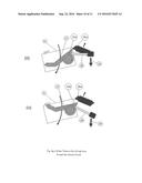
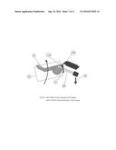
[0002] FIG. 1 shows an overall configuration of a mechanism that enables rotational-energy transfer from Liquid Environment (1) to Gas Environment (3) without allowing the liquid to leak into the Gas Environment (3). The Wall (2) divides the Liquid Environment (1) and Gas Environment (3). The Metal Cylindrical Container (16) contains parts that are flexible to rotate around Axial Center Line (4) so many degrees but less than 180 degrees. As the Input Sprocket (9) rotates in counter clockwise rotation, the Sprocket Teeth (7) of the input Sprocket (91 pushes down the Tooth (6) of Input Lever (10) in clockwise rotation, the detail of which will be explained in FIG. 3a through FIG. 3g-2. The clockwise rotation of the input Lever (10) will be transmitted to Output Lever (22) located in other side of the Wall (2), that is, the Gas Environment (3), via the Metal Cylindrical Container Assembly (16) and the Output Lever (22) rotates in the same direction of the input Lever (10), and the amount of the rotation of the Output Lever (22) will be the same as the amount of the rotation of the Input Lever (10). As the Output Lever (22) rotates, its Tooth (24) pushes up the Tooth (25) of Output Sprocket (26) (detail of which is explained in FIG. 3a through FIG. 3g-2) end forces the Output Sprocket (26) to rotate in the clockwise rotation.
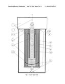
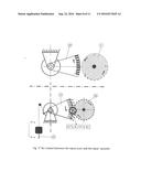
[0003] FIG. 2 shows cross-section of the Metal Cylindrical Container (16). As shown in FIG. 2, there are Layers of Chemical Rubber Layer Cylinder (19) made of noncorrosive and stretchable material such as chemical rubber (REMA Tip Top Chemical 4A or 4B or RT). Oil (18) is inserted between the layers to minimize the rubbing resistance between the layers. The Top Part (11) of the Chemical Rubber Layer Cylinder (19) is tightly fastened to outside of Cylinder (20) (Note that the side view of the Cylinder (20) after cut half vertically is shown). The Top Part (11) of the layers does not rotate around the Axial Center Line (4) while the Bottom Part (15) of the Chemical Rubber Layer Cylinder (19) swings alternatively in clockwise rotation and counter clockwise rotation as the Metal Shaft (12) swings alternatively in clockwise rotation and counter clockwise rotation. There is a gap between the Cylinder (20) and the Metal Shaft (12) such that the liquid may penetrate through Small Opening (5) into the Gap Space. But the liquid is not allowed to enter into the Gas Environmental (3). That is, the flexible Chemical Rubber layer Cylinder (19) blocks the flow of the liquid into the Gas Environment (3). This blocking is possible because the Bottom Part (15) of the Chemical Rubber Layer Cylinder (19) is fastened to the bottom part of the Metal Shaft (12) and the Top Part (11) of the Chemical Rubber Layer Cylinder (19) is tightly fastened to the top of the Cylinder (20), which blocks any flow of the liquid into the Gas Environment (3). Now as the Metal Shaft (12) rotates so many degrees (21) but less than 180 degrees in clockwise and counter clockwise, the top (11) of Chemical Rubber Layer Cylinder (19) stays fixed and does not rotate but the Bottom (15) of the Chemical Rubber Layer Cylinder (19) rotates alternatively in clockwise rotation and counter clockwise rotation along with the Metal Shaft (12).
[0004] Thus, the rotational-energy can be transmitted from the Input Sprocket (9 in FIG. 1) to the Output Sprocket (26 in FIG. 1) without leaking of the liquid from the Liquid Environment (1) into the Gas Environment (3).
[0005] FIG. 3a through FIG. 3g-2 in the following explain how the sprocket system works.
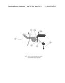
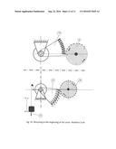
[0006] FIG. 3a shows the beginning of the operation. The figure in the upper section shows Input Sprocket (9) rotating in counter clockwise rotation. It should be noted that a large portion of the Input Sprocket (9) does not have sprocket teeth. The reason for this arrangement is to allow a period of disengagement between the Input Sprocket (9) and the Input Lever (10). The figure in the bottom section shows Output Lever (22) and Output Sprocket (26) placed in the Gas Environment (3). The contact of the gear tooth "B" of the Input Sprocket (9) with the gear tooth "F" of the Input Lever (10) is the beginning of the operation. As the Input Sprocket (9) rotates in counter clockwise rotation, the Output Sprocket (26) rotates in clockwise rotation. And the Weight (23) will rise up. Note that the Metal Cylindrical Container (16) connecting the Input Lever (10) and the Output Lever (22) is not shown.
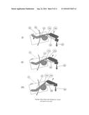
[0007] FIG. 3b shows a situation when the Input Lever (10) and the Output Lever (22) are rotated a half way up. The circled area at the center of the figure will be explained more detail in FIG. 3c.
[0008] FIG. 3c shows a situation when an Output Lever Tooth (22a) pushes the Tooth (26a) of Output Sprocket (26 in FIG. 3b) up as the Tooth Assembly Box (32) moves up. Here, the Lifting Force (31) is greater than the Gravity Force (29).
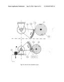
[0009] FIG. 3d shows a situation when the Input Lever (10) is just about to stop its clockwise rotation and gets ready to start rotating in counter clockwise rotation. Right after the last contact of the Output Lever (22) last Tooth (22a) with Tooth (26a) of the Output Sprocket (26) (see figure in the low section), the Weight Gravity Force (23) will pull the string down and initiate the clockwise rotation of the Output Lever (22). This is possible because after this last contact between the Tooth (10a) and the Tooth (9a) in this cycle, there will be no more teeth contact between then Input Sprocket (9) and the Input Lever (10) until the Tooth (9b) comes arround to contact with one of Input Lever (10) tooth. During this period, there will be no force that rotates the Input Lever (10) except the Weight Gravity Force (23). That is, during this period, the Input Sprocket (9) does not provide any torque (or force) to the Input Lever (10) to be rotated. Thus, the only Force (23), the gravity turns the Output Lever (22) in clockwise rotation, and at the same time, the Input Lever (10) in clockwise rotation right after the last contact. Note that the Metal Cylindrical Container (16) connecting the Input Lever (10) and the Output Lever (22) is not shown.
[0010] FIG. 3e depicts the last contact between the Output Lever Tooth (22a) and the Output Sprocket Tooth (26a) in this cycle.
[0011] FIG. 3f shows a situation when the Input Lever (10) and the Input Sprocket (9) are disengaged. This disengagement is due to the fact that there are no teeth in the Segment (ACB) of the Input Sprocket (9) and it allows the Weight Gravity Force (23) to pull the string down and cause the Output Lever (22) to rotate in clockwise rotation. FIG. 3g-1 and FIG. 3g-2 explain more detail.
[0012] FIG. 3g-1 and FIG. 3g-2 shows what is happening in 4 steps.
[0013] In FIG. 3g-1 (i), as the Tooth Assembly Box (32) moves downward, the Output Sprocket Tooth (26a) pushes the Output Lever Tooth (22a) upward, and it causes the Tooth Assembly (27) to rotate in counter clockwise rotation around the Hinge (33). Note that the reason for using the Tooth Assembly (27) instead of spring is to eliminate the spring maintenance requirement after the spring life cycle (e.g. 100,000 cycles) is expired.
[0014] FIG. 3g-1 (ii) shows the Tooth Assembly Box(32) rotated almost half way down and the Output Sprocket Tooth (26a) still pushes the Output Lever Tooth (22a) upward.
[0015] FIG. 3g-1 (iii) shows the moment when the disengagement between the Output Lever Tooth (22a) and the Output Sprocket Tooth (26a) occurs.
[0016] FIG. 3g-2 (iii) is a copy of FIG. 3g-1(iii).
[0017] FIG. 3g-2 (iv) is shown that as soon as the disengagement occurs, the Gravity Force (29) pulls down the Lever (30) and rotates the Tooth Assembly (27) in clockwise rotation and brings it back to the beginning of the cycle. Therefore, as long as there is no engagement between the Input Lever (10) and the Input Sprocket (9), the Tooth Assembly (27) repeats the clockwise rotation and counter clockwise rotation until the engagement between the Input Lever (10) and the Input Sprocket (9) occurs, and thus, the rotational energy gets transmitted from the Liquid Environment (1) into the Gas Environment (3).
[0018] FIG. 3h shows the beginning of the cycle.
[0019] Thus, the invented mechanism is able to transfer mechanical rotation energy generated in Liquid Environment (1) to Gas Environment (3) but does not avow the liquid penetration into the Gas Environment (3).
User Contributions:
Comment about this patent or add new information about this topic:
Images included with this patent application:
 |  |
 |  |
 |  |
 |  |
| Similar patent applications: | |
| Date | Title |
|---|---|
| 2016-10-13 | Fluid sample transfer adaptor and related methods and devices |
| 2016-10-13 | Stent for prosthetic heart valves |
| 2016-10-13 | Stent for prosthetic heart valves |
| 2016-10-13 | Tibial implant for knee prosthesis |
| 2016-10-13 | Transfer device for a stretcher |
| New patent applications in this class: | |
| Date | Title |
|---|---|
| 2022-09-22 | Electronic device |
| 2022-09-22 | Front-facing proximity detection using capacitive sensor |
| 2022-09-22 | Touch-control panel and touch-control display apparatus |
| 2022-09-22 | Sensing circuit with signal compensation |
| 2022-09-22 | Reduced-size interfaces for managing alerts |