Patent application title: Golf Stance Guide And Golf Stance Guide Container
Inventors:
IPC8 Class: AA63B6936FI
USPC Class:
1 1
Class name:
Publication date: 2016-09-22
Patent application number: 20160271476
Abstract:
A golf stance guide apparatus is disclosed. The golf stance guide
apparatus comprises a side strip, an upper horizontal strip and a lower
horizontal strip. The upper horizontal strip and the lower horizontal
strip are removable coupled, at right angle, to the side strip. The lower
horizontal strip may be adjusted by fitting inside one of a plurality of
hole in a bottom portion of the side strip. The side strip and the upper
horizontal strip, in combination, may provide coordinates for a golf
ball. Further, the lower horizontal strip may provide numeric positions
for left foot and right foot of a golfer. Furthermore, a golf stance
guide container for carrying the golf stance guide apparatus is also
disclosed.Claims:
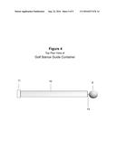
1. A golf stance guide apparatus comprising: a plurality of rectangular
strips, each of the plurality of rectangular strips having a plurality of
sections of equal width, the plurality of rectangular strips comprise: a
side strip comprising numerals in a top half portion and a plurality of
holes in a bottom half portion thereof, the numerals on the side strip
indicating a numeric position of a golf ball; an upper horizontal strip
removable coupled, at right angle, to one end of the side strip, each
section of the upper horizontal strip being marked alphabetically on left
and right from a center point to indicate alphabetical position of the
golf ball; and a lower horizontal strip removable coupled, at right
angle, to the side strip, each section of the lower horizontal strip, to
left and right from a center point, being marked with numerals and
wherein sections to the left of the center point indicates a numeric
position of a left foot of a golfer and numerals to the right of the
center point indicates a numeric position of a right foot of the golfer.
2. The golf stance guide apparatus of claim 1, wherein each of the plurality of sections in each strip is having a width equal to a diameter of the golf ball, the golf ball being a regulation size golf ball.
3. The golf stance guide apparatus of claim 1, wherein the center point in each of the upper horizontal strip and the lower horizontal strip is blacked out.
4. The golf stance guide apparatus of claim 1, wherein coordinates for a position of the golf ball being determined based on the alphabetic marking of the upper horizontal strip and the numerals marked on the lower horizontal strip.
5. The golf stance guide apparatus of claim 1, wherein positions of the left foot and the right foot of the golfer are determined through separate columns of numbers.
6. The golf stance guide apparatus of claim 1, wherein each of the plurality of strips is made up of one of Aluminum and plastic.
7. The golf stance guide apparatus of claim 1, wherein each of the plurality of strips has a thickness of 1/8 inch, a width of 3/4 inch and a length of 48 inches.
8. The golf stance guide apparatus of claim 1, wherein each of a leftmost end section and a rightmost end section of the upper horizontal strip has a machine screw in place by an internal tooth lock washer.
9. The golf stance guide apparatus of claim 1, wherein each of a leftmost end section and a rightmost end section of the lower horizontal strip has a machine screw in place by an internal tooth lock washer.
10. The golf stance guide apparatus of claim 1, wherein the lower horizontal strip is adjusted by fitting one end thereof into one of the plurality of holes in the bottom half portion of the side strip.
11. The golf stance guide apparatus of claim 1, wherein the plurality of rectangular strips are assembled to enable the golfer to determine coordinates for the golf ball and coordinates for feet of the golfer.
12. A golf stance guide container for carrying a golf stance guide comprising: a tubular structure including a rubber cap affixed at a bottom end and a removable plastic plug with a golf ball handle at a top end thereof; and layer of felt around a center section of the plastic plug for removable fitting the plastic plug inside the tubular object.
13. The golf stance guide container of claim 12, wherein the golf ball handle comprising a golf ball affixed to the plastic plug.
14. The golf stance guide container of claim 13, wherein the golf ball affixed to the plastic plug by means of a machine screw.
15. The golf stance guide container of claim 12, wherein the tubular structure is made up of one of a stainless steel and acrylic material.
16. The golf stance guide container of claim 12, wherein the tubular structure has a diameter of approximately 11/2 inch and length of 50 inches.
17. A golf stance guide container comprising: a tubular structure for carrying a golf stance guide apparatus, the golf stance guide apparatus comprising: a side strip; an upper horizontal strip; and a lower horizontal strip, the side strip and the upper horizontal strip are utilized to determine coordinates for a golf ball, and the lower horizontal strip is utilized for determining positions of a left foot and a right foot of a golfer, when the side strip, the upper strip and the lower strip are assembled for usage thereof, and wherein, the tubular structure is having a rubber cap affixed at a bottom end and a removable plastic plug with a golf ball handle at a top end thereof.
18. The golf stance guide container of claim 17 further comprising a layer of felt around a center section of the plastic plug for removable fitting the plastic plug inside the tubular object.
19. The golf stance guide container of claim 17, wherein the golf ball handle comprising a golf ball affixed to the plastic plug.
20. The golf stance guide container of claim 17, wherein the golf ball affixed to the plastic plug by means of a machine screw.
Description:
[0001] The Golf Stance Guide is a golf practice devise to be used by a
golfer at a golf driving range and will guide and assist the golfer with
finding and recalling the most effective feet and ball position for
effectively striking the golf ball for each of the different length golf
clubs in the golfer's golf bag.
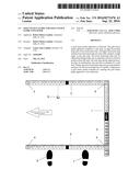
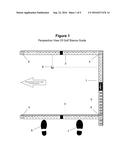
[0002] The Golf Stance Guide consists of 3 rectangular strips that are uniquely designed, lettered and numbered, machined, and assembled. These strips are made out of aluminum or plastic and are approximately 1/8 inch thick, 3/4 inch wide, and 48 inches long. The three strip are laid out on the green hitting mat at a golf driving range according to FIG. 2 if you are a right handed golfer. Part 1 is laid down first and positioned along the right edge of the green hitting mat and Part 2 and Part 3 are positioned at approximately 90 degrees with Part 1. The right side of Part 2 has a machine screw (Part 4) held in place with an internal thread lock washer (Part 9) that is inserted into the top hole of Part 1 and tightened with a screwdriver. The right side of Part 3 has a machine screw (Part 4) held in place with an internal thread lock washer (Part 9) that is inserted into one of the many holes in the bottom half of Part 1 and tightened with a screwdriver. By having a number of holes in the bottom half of Part 1 makes this device adjustable to the golfer. A short golfer or one using a shorter length golf club will insert Part 3 in any one of the holes closer to Part 2 into Part 1 when practicing. A tall golfer or one using a longer length golf club will insert Part 3 in any one of the holes furthest from Part 2 into Part 1 when practicing.
[0003] The Golf Stance Guide can be easily configured for left handed golfers by placing Part 1 along the left edge of the green hitting mat and positioning Part 2 and Part 3 at approximately 90 degrees with Part 1. The left side of Part 2 has a machine screw held in place with an internal thread lock washer that is inserted into the top hole of Part 1 and tightened with a screwdriver. The left side of Part 3 has a machine screw held in place with an internal thread lock washer that is inserted into one of the many holes in the bottom half of Part 1 and tightened with a screwdriver.
[0004] Once these strips are laid out and assembled they form an imaginary grid in the hitting area for the golfer (FIG. 2). The coordinates for the position of the golf ball will consists of an alphabetic column of letters as indicated on Part 2 and a numeric row of numbers as indicated on Part 1. The position of the left foot and right foot consists of a separate column of numbers. There is no corresponding row of numbers or letters for the feet position. Once the golfer has selected a golf club they will experiment with the position of the golf ball and experiment with the position of the feet in finding the most effective coordinates for effectively striking the golf ball solidly (in the center of the clubface) for each club. The golf ball coordinates and feet coordinates are then noted during the practice session (see Table 3) so that the golfer can recall the coordinates the next time they are at the golf practice range. Being able to practice and recall the most effective golf ball and feet position will eventually help the golfer on the golf course in effectively striking the golf ball and lowering their golf score.
[0005] In FIG. 2 if this was a 7 iron the golfer had selected and was hitting the golf ball effectively they will note the golf ball position and the feet position. In this case the golf ball will have an Alphabetic Coordinate of C, a Numeric Coordinate of 5, a left foot Numeric Coordinate of 6, and a right foot Numeric Coordinate of 6. If the golfer is miss-hitting the ball "thin" or on the edge of the clubface or miss-hitting the ball "fat" on the ground before hitting the clubface rather than in the center of the clubface they can make an adjustment in the position of the golf ball. This can be done by slightly moving the golf ball forward toward the letter D or slightly backward toward the letter B and noting the results. The Left Foot and Right Foot positions can also be adjusted forward or backward to accomplish the same results. If a golfer is miss-hitting the ball on the "toe" or miss-hitting the ball on the "heel" rather than in the center of the clubface they can make an adjustment in the position of the golf ball. This can be done by slightly moving the ball up toward the number 4 or slightly down toward the number 6 and noting the results.
[0006] Part #1 Perpendicular Member Strip.
[0007] This is a rectangular piece of aluminum or plastic and is approximately 1/8 inch thick, 3/4 inch wide and 48 inches long. The strip is sectioned off into equal width sections with each section exactly 1.68 inches wide, which is the exact diameter of a regulation size golf ball. According the Pro Golfer's Association Rule Book a regulation size golf ball must have diameter of 1.68 inches.
[0008] The top section of this strip is drilled and tapped to accept a 10-32 machine screw (Part 4) from the far right or far left section of Part 2. The sections below the top section are numbered starting with the number 1 and continuing to 10. These sections will form an imaginary row across the golfer's hitting area and will indicate the golf ball's numeric position. The remaining sections below the logo area are drilled and tapped to accept a 10-32 machine screw from the far right or far left section of Part 3.
[0009] Part #2 Upper Horizontal Member Strip.
[0010] This is a rectangular piece of aluminum or plastic 1/8 inch thick, 3/4 inch wide and 48 inches long. The strip is sectioned off into equal width sections (FIG. 2) with each section being exactly 1.68 inches wide. According to the Pro Golfer's Association Rule Book a regulation size golf ball must have a diameter of 1.68 inches. In the middle of this strip is a section that is blacked out to indicate the center of the strip or the center of the golfer's stance which will act as a reference point. The sections to the left of center and to the right of center are marked alphabetically starting with the letter A and continuing to the letter L. These letters will form an imaginary columns and will indicate the Alphabetic Position of the golf ball. The far left end section and the far right end section of this strip have a 10-32 machine screw held in place by an internal tooth lock washer and will fit into the top section of Part 1.
[0011] Part #3 Lower Horizontal Member Strip.
[0012] This is a rectangular piece of aluminum or plastic approximately 1/8 inch thick, 3/4 inch wide and 48 inches long. The strip is sectioned off into equal width sections (FIG. 2) with each section being exactly 1.68 inches wide.
[0013] According the Pro Golfer's Association Rule Book a regulation size golf ball must have a diameter of 1.68 inches. In the middle of this strip is a section that is blacked out to indicate the center of the strip or the center of the golfer's stance which will act as a reference point when the golfer is in their stance and addressing the golf ball. The sections to the left of center are numbered starting with the number 1 and continuing to 12. These numbers will form an imaginary columns and will indicate the Numeric Position of the golfer's left foot. The sections to the right of center are numbered starting with the number 1 and continuing to 12. These numbers will form an imaginary columns and will indicate the Numeric Position of the golfer's right foot. The far left end section and the far right end section of this strip have a 10-32 machine screw held in place by an internal tooth lock washer that will fit into one of the many holes in the bottom half section of Part 1.
[0014] Other inventions of this type have the golf ball hitting area outside the framework of the device and will indicate exactly where the golfer should put their left foot and exactly where the golfer should put their right foot. These other inventions do not take into account that golfers come in all different shapes sizes and heights. And each golfer has different length arms, different length torsos, and different length legs which in turn effect their optimal ball and feet position. With the Golf Stance Guide the hitting area of striking the golf ball is within the framework of the device and allows the golfer to experiment with the position of the golf ball and experiment with the position of the right and left foot in finding their best custom stance for effectively striking the golf ball for each of the different length clubs in the golfer's golf bag, and then noting the results.
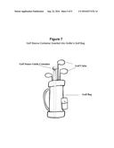
[0015] The Golf Stance Guide Container is a tubular shaped container to be used to store, transport, and protect the Golf Stance Guide. The Golf Stance Guide Container is made to fit in the golfer's golf bag if desired (FIG. 7).
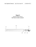
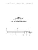
[0016] The Golf Stance Guide Container is made up of a stainless steel or acrylic tube approximately 1 inch in diameter and 52 inches long with a rubber cap that is glued on the bottom end and a removable plastic plug with golf ball handle on the top end (FIG. 4). The Golf Stance Guide will fit securely inside the Golf Stance Guide Container (FIG. 6). The removable top plug will fit snugly inside the tube which is accomplished by affixing a layer of felt around the center section of the plastic top plug (FIG. 5). This layer of felt will allow for enough compression for the plug to fit snugly inside the stainless steel tube. This compression will allow for a fit that is not to tight of a fit which would make the top plug difficult to remove or to loose of a fit that would allow the top plug to easily fall off and risk having the Golf Stance Guide fall out possibly damaging the Golf Stance Guide while in transit. At the end of this removable top plug is affixed a golf ball which will act as a handle. This handle will make inserting and removing the top plug easy in order to remove the Golf Stance Guide.
BRIEF DESCRIPTION OF THE VIEWS OF THE DRAWINGS
[0017] FIG. 1 illustrates a perspective view of a golf stance guide
[0018] FIG. 2 illustrates a top plan view of a golf stance guide.
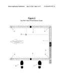
[0019] FIG. 3 illustrates a side plan view of a golf stance guide.
[0020] FIG. 4 illustrates a top plan view of a golf stance guide container
[0021] FIG. 5 illustrates an expanded view of a golf stance guide container.
[0022] FIG. 6 illustrates a cutaway view of a golf stance guide inserted into a golf stance guide container.
[0023] FIG. 7 illustrates a golf stance container inserted into a golf bag.
User Contributions:
Comment about this patent or add new information about this topic:
Images included with this patent application:
 |  |
 |  |
 |  |
 |  |
 |  |
| Similar patent applications: | |
| Date | Title |
|---|---|
| 2016-10-13 | Focus estimating device, imaging device, and storage medium storing image processing program |
| 2016-10-13 | System, method, and device for enhanced imaging device |
| 2016-10-13 | Control apparatus, method of controlling the same, and storage medium |
| 2016-10-13 | Imaging device and phase difference detection method |
| 2016-10-13 | Control apparatus, storage medium for storing control program, control method, and optical apparatus |
| New patent applications in this class: | |
| Date | Title |
|---|---|
| 2022-09-22 | Electronic device |
| 2022-09-22 | Front-facing proximity detection using capacitive sensor |
| 2022-09-22 | Touch-control panel and touch-control display apparatus |
| 2022-09-22 | Sensing circuit with signal compensation |
| 2022-09-22 | Reduced-size interfaces for managing alerts |