Patent application title: SELECTIVELY ATTACHED AND ORIENTED INDICATOR OF BODY POSITION AND MOVEMENT
Inventors:
IPC8 Class: AA63B6936FI
USPC Class:
1 1
Class name:
Publication date: 2016-09-22
Patent application number: 20160271474
Abstract:
A pointer rod may be selectively positioned on a person or apparatus held
and swung by a person and selectively positioned and oriented to provide
a visible magnified indication of the motion of position at which the
pointer rod is positioned.Claims:
1. A body position and rotation indicator comprising: a pointer rod; the
pointer rod extending from a base end to an indicating end opposite the
base end; a rod base; the base end of the pointer rod is rotationally
connected to the rod base to rotate about an axis that extends through
the pointer base; the rod base forming a generally flat rod base support
face that is generally parallel to the axis; a pointer base the pointer
base forming a generally flat pointer base support face the rod base
support face being sized to be selectively positionable against the
pointer base support face; and the pointer base and the rod base
constructed for the rod base support face and the pointer base support
face to be releasably secured to each other.
2. The body position and rotation indicator of claim 1 wherein: the rod base forms an edge adjacent to the pointer rod; the edge positioned and configured to be adjacent to the pointer rod as the pointer rod rotates about the axis; a series of pointer rod indicia marks is positioned along the edge; and a rod mark is positioned on the pointer rod adjacent to the edge whereby the pointer rod may be rotated about the axis to selectively position the angle of the pointer rod with respect to the rod base by reference to the rod mark and the series of pointer rod indicia marks.
3. The body position and rotation indicator of claim 1 further comprising a selectively actuated clamp for maintaining the pointer rod at a selected angle with respect to the rod base.
4. The body position and rotation indicator of claim 1 wherein: an outer periphery extends around the rod base support face; a series of pointer base indicia marks is positioned adjacent to the outer periphery of the rod base support face; and a pointer base mark is positioned on the pointer base adjacent to the pointer base support face whereby the rod base may be rotated on the pointer base support face to selectively position the angle of the rod base with respect to the pointer base by reference to the pointer base mark and the series of pointer base indicia marks.
5. The body position and rotation indicator of claim 1 wherein the rod base comprises a ferromagnetic material adjacent to rod base support face and the pointer base further comprises a magnet that forms the pointer base support face whereby is releasably secured to the pointer base by attraction of the rod base to the magnet of the pointer base.
6. A body position and rotation indicator comprising: a pointer rod; the pointer rod extending from a mounting end to an indicating end opposite the mounting end; a pointer base; the mounting end of the pointer rod is connected to the pointer base by a joint that allows to rotate in two planes with respect to the pointer base; the mounting end of the pointer rod is connected to the pointer base by a clamp that engages the mounting end of the pointer rod to the pointer base to prevent rotation and releases to allow the mounting end of the pointer rod to rotate with respect to the pointer base.
7. The body position and rotation indicator of claim 6 wherein a strap extends through the pointer base to secure the pointer base to a desired location on a person's body.
Description:
CROSS-REFERENCE TO RELATED APPLICATIONS/INCORPORATION BY REFERENCE
[0001] This application makes reference to, claims priority to, and claims benefit of U.S. Provisional Application Ser. No. 62/134,006, filed Mar. 17, 2015.
FIELD OF THE INVENTION
[0002] The invention relates to improved body control during physical activities, and more particularly to aiding a person's awareness of body position and motion during physical activities.
BACKGROUND OF THE INVENTION
[0003] Many people who decide to play a sport that requires grasping and swinging an apparatus to hit a ball, for example golf, fail to appreciate the importance of the rotation and movement of their body to the swing of the apparatus. Of particular importance to an effective swing are the relationships of body movement to the motion of a player's head, arms, wrists, head and legs.
[0004] A player who has not learned proper body rotation and movement for a sport may have very low body awareness making it difficult to produce the desired and effective timing and rhythm between arm motion and body rotation and motion that is required for efficient and repeatable movement. Both learning and maintaining proper body movement and rotation are important for performance in sports that require swinging an apparatus to hit a ball. Developing and maintaining optimal body rotation and movement for the sport's swinging movement is important for improvement in sports that entail swinging an apparatus such as a paddle, bat, club or racket.
BRIEF SUMMARY OF THE INVENTION
[0005] The invention concerns providing a visible indication of the motion of one or more locations on a person's body during a physical movement and for swinging an apparatus, a visible indication of the motion of the apparatus.
[0006] An aspect of the invention concerns indicating the motion and rotation of a person's body, as well as lack of motion, during physical movement.
[0007] Another aspect of the invention concerns indicating the motion and rotation of a person's body while swinging an apparatus.
[0008] It is yet a further object of the invention to provide a pointer that may be attached to a location on person's body and that will support an indicating object at an end of the pointer that is separated from the person's body.
[0009] Yet another aspect of the invention concerns providing a pointer that may be selectively attached to a base that is secured to a person.
[0010] It is yet another aspect of the invention provides a pointer that may be releasably attached to a base that is sized and constructed to be secured to an article that may be worn by a person such as clothing, a strap or a hat.
[0011] In another aspect, the invention provides a pointer that may be attached to a base at a selected position on the base and that may further be selectively positioned to extend from the base in a desired direction.
[0012] Still another object of the present invention is to provide a lightweight rod that extends outwardly from a specific location on a person's body or to a location on an apparatus such as a club, bat or racket to magnify the motion of the location in order to aid the person in developing body awareness which will lead to better connectivity between the arms and body.
BRIEF DESCRIPTION OF SEVERAL VIEWS OF THE DRAWINGS
[0013] FIG. 1 shows position and rotation indicator system according to the present invention.
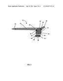
[0014] FIG. 2 is a side view of an adjustable pointer of the position and rotation indicator system shown by FIG. 1.
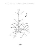
[0015] FIG. 3 is an oblique view of a second embodiment of an adjustable pointer according to the present invention.
[0016] FIG. 4 shows a person at a first position of a swing motion wearing the movement and rotation pointer at the person's waist.
[0017] FIG. 5 shows a person at a second position of a swing motion wearing the movement and rotation pointer at the person's waist.
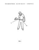
[0018] FIG. 6 shows a person grasping a golf club at a position of a swing motion having the movement and rotation pointer attached to the bill of a hat.
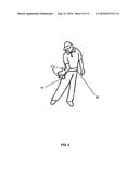
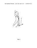
[0019] FIG. 7 shows a person grasping a golf club at a position of a swing motion having the movement and rotation pointer attached to a leg below the knee.
[0020] FIG. 8 shows a person grasping a golf club at a position of a swing motion having the movement and rotation pointer attached to the shaft of a golf club.
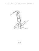
[0021] FIG. 9 shows a person grasping a golf club at a position of a swing motion having the movement and rotation pointer attached to an ankle.
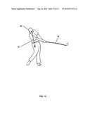
[0022] FIG. 10 shows a person grasping a golf club at a position of a swing motion having the movement and rotation pointer attached to a wrist.
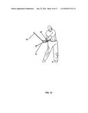
[0023] FIG. 11 shows a person grasping a golf club near a ball strike position of a swing motion having the movement and rotation pointer attached to the shaft of a golf club at the club head.
[0024] FIG. 12 shows a person grasping a golf club at a position of a swing motion having the movement and rotation pointer attached to the bill of a hat.
[0025] FIG. 13 shows a person grasping a golf club at a position of a swing motion having the movement and rotation pointer attached to a case for the indicator system.
DETAILED DESCRIPTION OF THE INVENTION
[0026] FIG. 1 shows a body position and rotation indicator system 10 according to the present invention. The indicator system 10 shows the motion and rotation locations on or portions of a person's body, e.g. hips, shoulders, chest, head, arms, legs etc. The pointer system 10 shows the motion and rotation of a person's body by an adjustable pointer 12 that extends outward from a point on a specific area of a person's body to which the pointer 12 is mounted. The pointer 12 amplifies the motion of the location of the person's body to which it is mounted to thereby helping the person to develop more body awareness and lead to better connectivity between the arms and body for a swing motion.
[0027] As shown by FIG. 2, the pointer 12 includes a lightweight rod 14 that extends from an indicating end 24 to a mounting end 22. The rod 14 is sufficiently stiff to avoid unacceptable deformation when moving with a person's body to thereby provide reliable indication of the person's body movement. The rod 14 is extensible so the distance from the indicating end 24 to the mounting end 22 may be set as desired. The rod 14 may be constructed of telescoping sections to provide adjustable length. The rod 14 is mounted to a rod pointer base 16 at the mounting end 22. A pin 26 extends along an axis and through the rod base 16 and the mounting end 22 of the rod 14. The rod 14 rotates about the axis that extends along pin 26 to change its angle position with respect to the rod base 16. The rod 14 rotates with respect to the rod base 16 in a plane that is perpendicular to the axis of pin 26.
[0028] Adjacent to the mounting end 22 of the rod 14, the rod base 16 forms a curved edge 32 that is generally centered at the pin 26. A series of indicia marks 34 extends along the curved edge 32. A rod mark 28 is on the rod 14 adjacent to the curved edge 32. Rotation of the rod 14 about the pin 26 moves the rod mark along the series of indicia marks 34 pointer base 16. The rod 14 may be rotated about the pin 26 to position the rod mark 28 adjacent to one of the indicia marks of the series 34. The angle of the rod 14 with respect to the rod base 16 is thereby set by a reference to the series of indicia marks 34. A lock lever 36 selectively locks the rotation of the rod 14 with respect to the rod base 16. The lock lever 36 may engage a clamp that squeezes the rod base 16 against the mounting end 22 of the rod 14. The angular position of the 14 with respect to the rod base 16 may thereby be set at a desired position and maintained at that position.
[0029] The rod base 16 extends from the pin 26 in a direction that is generally perpendicular to the pin 26 to a support face 38. The support face 38 of the rod base 16 is generally flat and circular. The support face 38 is generally parallel to the axis of pin 26. A series of indicia marks 42 extends around the rod base 16 adjacent to the support face 38. The rod base 16 is made of a ferromagnetic material at the support face 38.
[0030] A pointer base 18 includes a magnet 44 that forms a generally flat support face 46. The support face 46 is sized and shaped to generally conform to the support face 38 of the rod base 16. A pointer base mark 48 is on the pointer base 18 adjacent to the support face 46. Rotation of the pointer base 16 on the support face 46 moves the series of indicia marks 42 past the pointer base mark 48 so that the position of the rod base 16 with respect to the pointer base 18 may be set by reference to the series of indicia marks 42. The magnet 44 exerts a sufficient attraction on the rod base 16 to maintain the rod base 16 on the magnet 44 in the selected orientation for motion of the pointer base 18 with a person's body during motion.
[0031] The pointer base 18 movement with the rotation/movement of the body part it is attached to provides immediate and magnified feedback to that body part's movement. The extent and speed of the rotation/movement is more visible the farther the rod 14 extends outward.
[0032] FIG. 3 shows another body position and rotation indicator having an adjustable pointer 12 according to the present invention. The adjustable pointer 12 shown by FIG. 3 includes an extensible pointer rod 114 extends from an indicating end 124 to a mounting end 122. The pointer rod 114 is sufficiently stiff to avoid unacceptable deformation when moving with a person's body to thereby provide reliable indication of the person's body movement. The rod 14 is extensible and may be extended along its length as indicated by arrow 131 to an extended configuration shown in phantom at 132.
[0033] The mounting end 122 engages a pointer base 116 that engages a strap 62 which may be secured to a person to position the pointer base 116 at a desired position on the person's body. The mounting end 122 engages the pointer base 116 to form an articulating joint. The mounting end 122 may thereby rotate with respect to the pointer base 116 in two planes as indicated by arrows 133 and 135 to positions 134 and 136, respectively, as shown in phantom.
[0034] The articulating joint formed by the mounting end 122 and the pointer base 116 may be secured by a clamp that is actuated by rotations of the pointer rod about its length as shown by arrows 141 and 143. The articulating joint formed by mounting end 122 and the pointer base 116 may be released by rotation of the pointer rod 114 as indicated by the arrow 141. The pointer rod 114 then rotated as indicated by arrows 133 and 135 to a desired direction, and the pointer rod then engaged to the pointer base 116 by rotating the pointer rod 114 as indicated by the arrow 143.
[0035] Referring again to FIG. 1, system 10 includes a clip 52 that includes a pointer base 18. The clip 52 is sized so that it will engage and remain attached to a strap of a golf glove or to a seam or bill of a hat. The clip 52 thereby provides a means for mounting the pointer base 18 to a golf glove or hat, and thereby provides for magnetically mounting the rod base to the glove or hat. The direction that the rod 14 extends from the hat or glove may be selected by rotation of the rod 14 about the pin 26 as described above, and by rotating the pointer base 16 on the magnet 44 as also described above.
[0036] The system 10 shown by FIG. 1 also includes an end of grip fastener 54 that includes a pointer base 18. The end of grip fastener 54 may be affixed to the end of the grip of a golf club or racket. When affixed to the end of a grip, the grip fastener 54, the pointer base 18 is positioned such that the support face 46 of the magnet 44 faces generally along the club or racket and away from the club or racket. Again, the rod base 16 may be selectively positioned on and magnetically held to the pointer base 18 as previously described, and the direction that angle that the rod 14 extends from the rod base 16 may be selected as previously described.
[0037] The system 10 shown by FIG. 1 further includes a shaft clamp 56 that includes a pointer base 18. The shaft clamp 56 may be affixed to the shaft of a golf club. The support face 46 of the magnet 44 of the pointer base 18 faces generally perpendicular to the shaft to which the clamp is attached. Yet again, the rod base 16 may be magnetically held to the base 18 and the direction that the rod 14 extends may be selected as previously described.
[0038] The system 10 shown by FIG. 1 also includes a buckle 58 that includes a pointer base 18. The two sections of buckle 58 may be secured to opposite ends of straps 62. The support face 46 of the magnet 44 of the pointer base 18 faces generally outwardly from the buckle and therefore away from a person around whom the strap 62 is positioned. As for the other attachments that include a pointer base 18, the rod base 16 may be magnetically held to the base 18 and the direction that the rod 14 extends may be selected as previously described.
[0039] Similar to the straps 62 and buckle 58, the system 10 shown by FIG. 1 also includes a forearm strap 64 with a pointer base 18. Again, the support face 46 of the magnet 44 of the pointer base 18 faces generally outwardly and away from a person around whom the strap 64 is positioned. As for the other attachments that include a pointer base 18, the rod base 16 may be magnetically held to the base 18 and the direction that the rod 14 extends may be selected as previously described.
[0040] The most important aspect of this invention is its versatility. The lightweight rod is adjustable in length. Additionally, the rod can swivel and lock to point in any direction. The Body Rotation/Movement Rod will come with adjustable straps in different lengths to account for the wide range of circumferences depending on what body part the pointer is fixed to.
[0041] As shown by FIG. 2, the indicating end 24 may be a conical or rounded end of the rod 14. The indicating end 24 may rather include a means for attaching an indicator to that end. Any suitable means for attachment may be used including threads, clips, adhesive or friction attachment. The system 10 shown by FIG. 1 includes two indicators that may be attached to the indicating end 24. The soft foam ball 66 may be mounted to the indicating end 24 to provide a large visual cue to a person using the indicator system 10. The mount 68 may be attached to the indicating end 24 to support other indicators including accelerometer and position indicating electronic indicators that may communicate by Bluetooth or other communication technology.
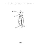
[0042] FIG. 4 shows a person having an adjustable pointer 12 attached to a strap 62. The pointer 12 is positioned to extend generally parallel to the ground and outwardly from the person's hip. In this position, the pointer 12 will aid the person in developing a golf swing by providing an indication for position of the person's elbow during a golf swing.
[0043] FIG. 5 shows a person having the pointer 12 attached to a strap 62 during a golf swing motion. The pointer 12 is positioned to extend outwardly from the person's hip and will rotate with the person's hip. In this position, the pointer 12 will provide a visual indication to the person of the desired movement of the person's arm with the rotation of the person's body during a golf swing.
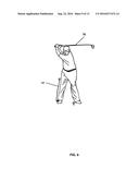
[0044] FIG. 6 shows a person grasping a golf club 78 and having the pointer 12 attached to the bill of a hat 82. The pointer 12 may be secured to the bill of the hat 82 by the clip 52. In this position, the pointer 12 will provide a visual indication to the person of the desired position of the person's head for a golf swing.
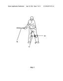
[0045] FIG. 7 shows a person grasping a golf club 78 and having an adjustable pointer 12 attached to a leg below a knee by a strap 62. The pointer 12 is positioned to extend generally parallel to the ground and outwardly from the person's leg. In this position, the pointer 12 will aid the person in developing a golf swing by providing an indication for position of the person's leg.
[0046] FIG. 8 shows a person grasping a golf club 78 to which the pointer 12 is attached. The pointer 12 may be secured to club shaft by the shaft clamp 56. In this position, the pointer 12 will provide a visual indication to the person of the desired position and motion of golf club 78 for a golf swing.
[0047] FIG. 9 shows a person grasping a golf club 78 and having an adjustable pointer 12 attached to an ankle. The adjustable pointer 12 may be attached by a strap 62. The pointer 12 is positioned to extend generally upwardly along the person's lower leg. In this position, the pointer 12 will aid the person in developing a golf swing by providing an indication for position of the person's leg.
[0048] FIG. 10 shows a person grasping a golf club 78 and having an adjustable pointer 12 attached to a wrist. The adjustable pointer 12 is attached by a strap 62. The pointer 12 is positioned to extend generally along and beyond the person's forearm. In this position, the pointer 12 will aid the person in developing a golf swing by providing an indication of movement of the person's forearm.
[0049] FIG. 11 shows a person grasping a golf club 78 to which the pointer 12 is attached. The swing shown by FIG. 11 is near the ball strike position. The pointer 12 may be secured to the club shaft by the shaft clamp 56. In this position, the pointer 12 will provide a visual indication to the person of the desired position and motion of golf club 78 at the ball strike position.
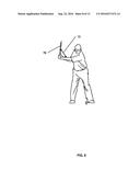
[0050] FIG. 12 shows a person grasping a golf club 78 and having the pointer 12 attached to the bill of a hat 82. The person is at a follow through position of a golf club swing. The pointer 12 may be secured to the bill of the hat 82 by the clip 52. In this position, the pointer 12 will provide a visual indication to the person of the desired position of the person's head for a golf swing.
[0051] FIG. 13 shows a person swinging a golf club 78 and the pointer 12 is attached to the pointer base 18 positioned on a case 76 as illustrated by FIG. 1. Pointer 12 remains stationary providing the person with a visual reference for a golf club swing.
[0052] While the present invention has been described with reference to certain embodiments, it will be understood by those skilled in the art that various changes may be made and equivalents may be substituted without departing from the scope of the present invention. In addition, many modifications may be made to adapt a particular situation or material to the teachings of the present invention without departing from its scope. For example, a rod base and pointer base may be selectively engaged other than magnetically with flat contacting surfaces such as by being formed to physically engage each other and may include releasable retaining apparatus such as a clip.
[0053] Therefore, it is intended that the present invention not be limited to the particular embodiment disclosed, but that the present invention will include all embodiments falling within the scope of the appended claims.
User Contributions:
Comment about this patent or add new information about this topic:
Images included with this patent application:
 |  |
 |  |
 |  |
 |  |
 |  |
 |  |
| Similar patent applications: | |
| Date | Title |
|---|---|
| 2016-10-13 | Power supply voltage detection and power delivery circuit |
| 2016-10-13 | Drive controller of instrument |
| 2016-10-13 | Band optimised rf switch low noise amplifier |
| 2016-10-13 | Asymmetric gate driver apparatus, methods, and systems |
| 2016-10-13 | Widely tunable short cavity laser |
| New patent applications in this class: | |
| Date | Title |
|---|---|
| 2022-09-22 | Electronic device |
| 2022-09-22 | Front-facing proximity detection using capacitive sensor |
| 2022-09-22 | Touch-control panel and touch-control display apparatus |
| 2022-09-22 | Sensing circuit with signal compensation |
| 2022-09-22 | Reduced-size interfaces for managing alerts |