Patent application title: SPORTBALL CAPABLE OF SENSING PRESSURE AND FEEDBACK CONTROL SYSTEM
Inventors:
IPC8 Class: AA63B2400FI
USPC Class:
1 1
Class name:
Publication date: 2016-09-08
Patent application number: 20160256743
Abstract:
A sportball giving feedback as to manner in which it is handled or struck
includes a ball body, and a plurality of sensors, a first wireless
communication unit, and a controller located in the ball body. The
sensors are arranged at different locations in the ball body, and are
configured to sense pressures at different locations of the ball body,
and generate electrical signals accordingly. The controller is configured
to obtain the generated electrical signals, determine some
characteristics of the pressures applied, and transmit the determined
characteristics to the electronic device via the first wireless
communication unit.Claims:
1. A sportball capable of wirelessly communicating with an electronic
device, the sportball comprising: a ball body made of an elastic
material; a plurality of sensors located in and arranged at different
locations in the ball body, the plurality of sensors configured to sense
pressures at different locations of the ball body, and generate
electrical signals according to the sensed pressures; a first wireless
communication unit located in the ball body; and a controller located in
the ball body and configured to: obtain the generated electrical signal;
determine a characteristic data of the pressures according to the
obtained electrical signals; and transmit the determined characteristic
data to the electronic device via the first wireless communication unit,
the determined characteristic data configured to command the electronic
device to compare the determined characteristic data with a standard
characteristic data and generate feedback information according to a
result of comparison.
2. The sportball of claim 1, wherein the sensors comprise pressure sensors configured to sense a value of the pressures; and the determined characteristic data of the pressures comprises the value of the pressures.
3. The sportball of claim 2, wherein the controller is further configured to determine a range of an area to which the pressures are applied and sensed according to the sensors which generate the electrical signals, and determine a posture employed by a user according to the determined range; the determined characteristic data of the pressures further comprises the posture employed by the user.
4. The sportball of claim 1, wherein the sensors comprises motion sensors configured to sense a direction of the pressures; the determined characteristic data of the pressures comprises the direction of the pressures.
5. The sportball of claim 4, wherein the motion sensors are further configured to sense an acceleration and a velocity of the ball body as a result of the pressures; the determined characteristic data of the pressures further comprises the acceleration and the velocity of the ball body.
6. The sportball of claim 1, wherein the feedback information is an advice which is output by the electronic device.
7. The sportball of claim 1, wherein the feedback information is a control command comprising a feedback data corresponding to the result of comparison; the control command is configured to control the sportball to generate feedback according to the feedback data when the electronic device transmits the control command to the sportball.
8. The sportball of claim 7, wherein the feedback is a vibration feedback; the sportball further comprises a vibrator located in the main body; the processor is electrically connected to the vibrator, and is configured to control the vibrator to vibrate according to the feedback data after the electronic device receives the control command, thereby providing the vibration feedback to the user.
9. The sportball of clam 8, wherein the feedback data is an amplitude of the vibration feedback.
10. The sportball of claim 7, wherein the feedback is visual feedback; the sportball further comprises a plurality of LEDs located in the ball body; the controller is electrically connected to the LEDs, and is configured to control the LEDs to emit light according to the feedback data after the electronic device receives the control command, thereby providing the visual feedback to the user.
11. The sportball of claim 10, wherein feedback data is an intensity of the emitted light.
12. The sportball of claim 1, wherein the ball body comprises an exterior surface and an opposite interior surface, to cause the ball body to be divided into a ball wall between the exterior and the interior surface, and a cavity surrounded by the interior surface; the sensors are located in the ball wall; the controller and the first wireless communication unit are located in the cavity.
13. The sportball of claim 12, wherein the cavity is substantially regular polyhedron in shape; the sensors are attached to each sidewall of the cavity.
14. The sportball of claim 12, wherein the exterior surface further comprises a power jack.
15. A pressure sensing and feedback controlling system comprising: a sportball comprising: a ball body made of an elastic material; a plurality of sensors located in and arranged at different locations in the ball body, the plurality of sensors configured to sense pressures at different locations of the ball body, and generate electrical signals according to the sensed pressures; a first wireless communication unit located in the ball body; and a controller located in the ball body, and configured to obtain the generated electrical signals, determine a characteristic data of the pressures according to the obtained electric signals; an electronic device to receives the determined characteristic data transmitted from the sportball via the first wireless communication unit, and comprising: a processor to compare the determined characteristic data with a standard characteristic data, and generate feedback information according to a result of comparison.
16. The system of claim 15, wherein the feedback information is an advice; the processor is further configured to control the electronic device to output the advice.
17. The system of claim 16, wherein the electronic device further comprises a memory for storing the standard data and an advice template; the processor is configured to obtain the advice template from the memory, and generate the advice according to the result of comparison and the obtained advice template.
18. The system of claim 15, wherein the electronic device further comprises a network interface; the processor is configured to obtain the standard data from a preset network via the network interface when the electronic device receives the determined characteristic data from the sportball.
19. The system of claim 15, wherein the feedback information is a control command comprising feedback data corresponding to the result of comparison; the electronic device further comprises a second wireless communication unit; the processor is further configured to transmit the control command to the sportball via the second wireless communication unit, to command the sportball to generate feedback according to the feedback data.
Description:
FIELD
[0001] The subject matter herein generally relates to data collection and feedback.
BACKGROUND
[0002] Nowadays, ball games are one of the most popular sports throughout the world. Daily ball games or ball training often lacks sufficient feedback to facilitate users' skill improvement. Taking a basketball for example, shooting baskets is a critical skill. However, the user may not know whether his or her shooting posture or technique is correct since a measurement of force the user applies to the basketball may not be available. As a result, the user is unable to adjust his or her shooting posture or technique from feedback.
BRIEF DESCRIPTION OF THE DRAWINGS
[0003] Implementations of the present technology will now be described, by way of example only, with reference to the attached figures.
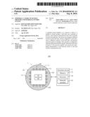
[0004] FIG. 1 is a block diagram of an embodiment of a pressure sensing and feedback controlling system employed by a sportball.
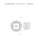
[0005] FIG. 2 is similar to FIG. 1, but showing the pressure sensing and feedback controlling system in another embodiment.
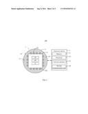
[0006] FIG. 3 is similar to FIG. 1, but showing the pressure sensing and feedback controlling system in yet another embodiment.
DETAILED DESCRIPTION
[0007] It will be appreciated that for simplicity and clarity of illustration, where appropriate, reference numerals have been repeated among the different figures to indicate corresponding or analogous elements. In addition, numerous specific details are set forth in order to provide a thorough understanding of the embodiments described herein. However, it will be understood by those of ordinary skill in the art that the embodiments described herein can be practiced without these specific details. In other instances, methods, procedures, and components have not been described in detail so as not to obscure the related relevant feature being described. Also, the description is not to be considered as limiting the scope of the embodiments described herein. The drawings are not necessarily to scale and the proportions of certain parts may be exaggerated to better illustrate details and features of the present disclosure.
[0008] Several definitions that apply throughout this disclosure will now be presented.
[0009] The term "substantially" is defined to be essentially conforming to the particular dimension, shape, or other feature that the term modifies, such that the component need not be exact. For example, "substantially cylindrical" means that the object resembles a cylinder, but can have one or more deviations from a true cylinder. The term "comprising," when utilized, means "including, but not necessarily limited to"; it specifically indicates open-ended inclusion or membership in the so-described combination, group, series and the like.
[0010] FIG. 1 illustrates an embodiment of a pressure sensing and feedback controlling system 100. The system 100 includes a sportball 1 and an electronic device 2. The sportball 1 can wirelessly communicate with the electronic device 2. The sportball 1 can be a football, a baseball, a basketball, a golf ball, an American football, a badminton shuttle, or any object intended to be handled or struck. The electronic device 2 can be any mobile terminal (such as a smart phone, a tablet computer, or a multimedia player) having a wireless communication function. The electronic device 2 can also be a cloud server.
[0011] The sportball 1 includes a ball body 10, a number of sensors 20, and a controller 30. The ball body 10 is made of elastic material such as rubber. The sensors 20 are located in and arranged at different locations in the ball body 10. When the ball body 10 is pressed by a user (taking a basketball for example, when the user's hand touches the basketball during dribbling or shooting the basketball), the user applies an original and external pressure, such original and external pressure to be delivered from the ball body 10 to at least one sensor 20, and then sensed by the at least one sensor 20.
[0012] The sensors 20 sense pressures at different locations of the ball body 10, and generate electrical signals according to the sensed pressures. The controller 30 is located inside the ball body 10, and is electrically connected to each of the sensors 20. The controller 30 obtains the generated electrical signals, and determines a characteristic data of the pressures applied according to the obtained electric signals. Since the sensors 20 are located in the ball body 10, the ball body 10 may absorb a portion of the original pressures to cause the pressures sensed by the sensors 20 to be less than the original pressures. In at least one embodiment, the elastic material of the ball body 10 has a moderate elasticity. As such, the ball body 10 can have enough elasticity to effectively reflect the amount of the original pressures. That is, the ball body 10 can effectively deliver the original pressures to the sensors 20, to cause the amount of the pressures sensed by the sensors 20 to be nearly identical to the original pressures.
[0013] In at least one embodiment, the sensors 20 include pressure sensors, such as piezoelectric sensors or capacitive type sensors. The pressure sensors sense the value of the pressures, and generate electric signals according to the sensed value of the pressures. The controller 30 obtains the generated electrical signals, and determines the value of the pressures according to the obtained electric signals. That is, the determination of the characteristic data of the pressures applied to the sportball 1 being handled or struck includes the value of the pressures. In addition, the controller 30 further determines a range of the area to which the pressures are applied and sensed according to the sensors 20 which generate the electrical signals, and determines a posture of the employed by the user to the ball body 10 according to the determined range. That is, the determination of the characteristic data of the pressures further includes the posture employed by the user.
[0014] The sensors 20 can further include motion sensors such as three-axis gyroscopes, gravity sensors, or acceleration sensors. The motion sensors sense the direction of the pressures, and generate electrical signals according to the sensed direction of the pressures. The controller 30 obtains the generated electrical signals, and determines the direction of the pressures according to the obtained electric signals. That is, the determination of the characteristic data of the pressures includes the direction of the pressures. The motion sensors can further sense the acceleration and the velocity of the ball body 10 as a result of the pressures. Thus, the determination of the characteristic data of the pressures further includes the acceleration and the velocity of the ball body 10.
[0015] The sportball 1 further includes a first wireless communication unit 40 located in the ball body 10. The controller 30 further transmits the determined characteristic data to the electronic device 2 via the first wireless communication unit 40. The first wireless communication unit 40 can be a BLUETOOTH.RTM. communication unit or a WIFI communication unit.
[0016] The electronic device 2 includes a processor 22. When the electronic device 2 receives the determined characteristic data from the sportball 1, the processor 22 compares the determined characteristic data with data as to a certain standard (standard data), and generates feedback information according to the result of comparison. As such, the user can learn whether his handling or striking of the sportball 1, including the values of the pressures, the posture employed by the user, the direction of the pressures, and/or the acceleration and velocity of the sportball 1, matches or does not match a certain standard according to the feedback information, and then improve his or her technique as required.
[0017] In at least one embodiment, the feedback information is an advice. The advice can be an audio file or a text file. The processor 22 further controls the electronic device 2 to output the advice to the user. In at least one embodiment, the electronic device 2 further includes a memory 21 for storing an advice template. Taking a basketball for example, the advice template can be "the pressure applied is insufficient/too great/suitable; the posture employed is correct/incorrect; the acceleration and velocity of the sportball 1 is insufficient/too great/suitable." The processor 22 obtains the advice template from the memory 21, and generates the advice according to the result of comparison and the obtained advice template. The standard data can be stored in the memory 21, and is provided by a professional coach or a professional athlete. When the electronic device 2 is a mobile terminal, the standard data can also be obtained by the electronic device 2 via a preset network. In this case, the electronic device 2 further includes a network interface 23. The processor 22 obtains the standard data from the preset network via the network interface 23 when the electronic device 2 receives the determined characteristic data from the sportball 1.
[0018] In another embodiment, the feedback information is a control command. The control command includes feedback data corresponding to the result of comparison. Referring to FIGS. 2-3, in this embodiment, the electronic device 2 further includes a second wireless communication unit 24. The processor 22 further transmits the control command to the sportball 1 via the second wireless communication unit 24, to command the sportball 1 to generate feedback according to the feedback data. Here, the user can learn whether his handling or striking is correct or not correct according to the feedback data.
[0019] In at least one embodiment, the feedback is a tactile feedback, more specifically, a vibration feedback. Referring to FIG. 2, the sportball 1 in this embodiment further includes a vibrator 31 located in the main body 10. The processor 30 is electrically connected to the vibrator 31, and controls the vibrator 31 to vibrate according to the feedback data after the electronic device 2 receives the control command, thereby providing the vibration feedback to the user. For example, the feedback data is the amplitude of the vibration feedback. When the user' handling or striking is not correct, the controller 30 controls the vibrator 31 to vibrate with great amplitude to indicate error or non-correctness in handling or striking Otherwise, the controller 30 controls the vibrator 31 to vibrate with small amplitude. As such, the user can learn whether his handling or striking is correct or not according to the amplitude of the vibration.
[0020] In yet another embodiment, the feedback is a visual feedback. Referring to FIG. 3, the sportball 1 further includes a number of LEDs 32 located in the ball body 10. The controller 30 is electrically connected to the LEDs 32, and controls the LEDs 32 to emit light according to the feedback data after the electronic device 2 receives the control command, thereby providing the visual feedback to the user. For example, the feedback data is the intensity of the light emitted by the LEDs 32. When the user' handling or striking is not correct, the controller 30 controls the LEDs 32 to emit light of high intensity to indicate error or non-correctness in handling or striking Otherwise, the controller 30 controls the LEDs 32 to emit light of low intensity. As such, the user can learn visually. In this embodiment, the elastic material used to make the ball body 10 is transparent to allow the emitted light to be seen.
[0021] In at least one embodiment, the sportball 1 is spherical, for example, a football, a baseball, a basketball, or a golf ball. The ball body 10 includes a spherical exterior surface 11 and an opposite interior surface 12. The ball body 10 is divided into a ball wall 101 between the exterior 11 and the interior surface 12, and a cavity 102 surrounded by the interior surface 12. The ball wall 101 is made of elastic material. The sensors 20 are located in the ball wall 11, namely, the sensors 20 are embedded in the elastic material. The controller 30 and the first wireless communication unit 40 are located in the cavity 102. The cavity 102 is substantially regular polyhedron (such as cube as shown in FIGS. 1-3) in shape, the sensors 20 are attached to each sidewall of the cavity 102. In another embodiment, the cavity 102 can also be spherical. The interior 12 further defines a number of through holes (not shown) to allow the wires connecting the sensors 20 and the controller 30 to pass through.
[0022] The exterior surface 11 further includes a power jack 13 electrically connected to a peripheral device (not shown). One or more batteries (not shown) of the sportball 1 can be charged via the power jack 13. The power jack 13 can be a USB power jack or a wireless power jack.
[0023] In another embodiment, the sportball 1 can be non-spherical, for example an American football or a badminton shuttle. In this embodiment, the shape of the ball body 10 can be varied according to need.
[0024] It is to be understood, even though information and advantages of the present embodiments have been set forth in the foregoing description, together with details of the structures and functions of the present embodiments, the disclosure is illustrative only; changes may be made in detail, especially in matters of shape, size, and arrangement of parts within the principles of the present embodiments to the full extent indicated by the plain meaning of the terms in which the appended claims are expressed.
User Contributions:
Comment about this patent or add new information about this topic:
Images included with this patent application:
 |  |
 |  |
| New patent applications in this class: | |
| Date | Title |
|---|---|
| 2022-09-22 | Electronic device |
| 2022-09-22 | Front-facing proximity detection using capacitive sensor |
| 2022-09-22 | Touch-control panel and touch-control display apparatus |
| 2022-09-22 | Sensing circuit with signal compensation |
| 2022-09-22 | Reduced-size interfaces for managing alerts |