Patent application title: Apparatus and Method for Physical Exercise
Inventors:
IPC8 Class: AA63B2100FI
USPC Class:
1 1
Class name:
Publication date: 2016-09-08
Patent application number: 20160256723
Abstract:
A device and method for exercise are presented. The device includes a
first vertical member and a second vertical member, each with adjustable
lengths. A first horizontal member is disposed through a first hole in
each of the first and second vertical members. The first horizontal
member is adjustable in length. A second horizontal member may be
disposed through a second hole in each of the first and second vertical
members. The first and second vertical members and the first horizontal
member may be adjusted to provide an interference fit in door frame. For
example, the lengths of the first and second vertical members and the
length of the first horizontal member may be adjusted until ends of each
member are in contact with corresponding door jambs of a door frame.Claims:
1. A hamstring exercise device for use by an individual, comprising: a
first vertical member having an adjustable length and configured to be
secured to a door frame by adjusting the length to provide an
interference fit with the door frame; a second vertical member having an
adjustable length and configured to be secured to the door frame by
adjusting the length to provide an interference fit with the door frame;
and a first horizontal member configured to be removably disposed through
a first hole in each of the first and second vertical members, and
wherein the first holes are at a height of the first and second vertical
members whereby a posterior of the ankles of the individual may be held
near a floor by the first horizontal member.
2. The device of claim 1, wherein the first horizontal member has an adjustable length and is configured to be secured to the door frame by adjusting the length to provide an interference fit with the door frame.
3. The device of claim 2, wherein one or more of the first vertical member, the second vertical member, and the first horizontal member are telescoping.
4. The device of claim 3, wherein the telescoping member(s) are configured to be locked at respective adjusted lengths.
5. The device of claim 1, further comprising: a second horizontal member configured to be removably disposed through a second hole in each of the first and second vertical members, and wherein the second holes are at a height of the first and second vertical members which is higher than the respective first holes.
6. The device of claim 5, further comprising one or more assistance members connected to the second horizontal member, the first vertical member, and/or the second vertical member.
7. The device of claim 6, wherein the one or more assistance members are elastic bands.
8. The device of claim 1, wherein one or more of the first vertical member, the second vertical member, and the first horizontal member have a non-circular cross-section.
9. The device of claim 8, wherein one or more of the first vertical member, the second vertical member, and the first horizontal member have a cross-section shape that is elliptical or rectilinear.
10. The device of claim 1, further comprising: a first coupling sleeve slidingly disposed on the first vertical member; a second coupling sleeve slidingly disposed on the second vertical member; and a third horizontal member spanning from the first coupling sleeve to the second coupling sleeve.
11. The device of claim 10, wherein each of the first and second coupling sleeves includes a lock for securing each of the first and second coupling sleeve at a fixed vertical position on the first and second vertical members, respectively.
12. A method, comprising: providing a first vertical member and a second vertical member, each having an adjustable length; disposing a first horizontal member through a first hole in each of the first and second vertical members to form an assembly, wherein the first horizontal member has an adjustable length; fitting the assembly into a door jamb such that an end portion of each of the first and second vertical members and ends of the first horizontal member are in contact with the door jamb and adjacent to door stops of the doorjamb; and while a user is kneeling, placing the ankles of the user under the first horizontal member such that a posterior of the ankles contacts the first horizontal member and the first horizontal member limits vertical movement of the ankles.
13. The method of claim 12, wherein fitting the assembly into a door jamb may further comprise adjusting the lengths of each of the first and second vertical members and the first horizontal member to provide an interference fit with to the door frame.
14. The method of claim 12, further comprising disposing a second horizontal member through a second hole in each of the first and second vertical members, wherein the second horizontal member has an adjustable length.
Description:
CROSS-REFERENCE TO RELATED APPLICATIONS
[0001] This application claims priority to U.S. Provisional Application No. 62/129,022, filed on Mar. 5, 2015, now pending, the disclosure of which is incorporated herein by reference.
FIELD OF THE DISCLOSURE
[0002] The invention relates to an apparatus used for physical conditioning and therapy.
BACKGROUND OF THE DISCLOSURE
[0003] Recent evidence supports the importance of balanced hamstring-to-quadriceps strength in reducing the risk of injury among participants of sports that require running, jumping, or kicking. Moreover, hamstring injuries are the most common soft-tissue injury in individuals who engage in sprinting and organized sports. The importance of avoiding this injury is magnified by the fact that an average of one in four hamstring injuries will recur. These findings have prompted researchers to investigate the most effective means of correcting muscle imbalances and rehabilitating hamstring injuries. Current research shows that regardless of sport type, eccentric hamstring loading is the most effective way to build strength and prevent hamstring injuries, as well as to rehabilitate hamstring injuries. Finally, the strength and history of hamstring muscle injuries is a major predictor of future trauma to structures in which the hamstring acts as a major stabilizer, including the knee. For example, recent findings suggest that hamstring strength deficits or previous damage is a major risk factor for debilitating injuries of the anterior cruciate ligament (ACL) due to altered hamstring muscle activation.
[0004] Given the strong support for eccentric hamstring loading, studies have compared various eccentric exercise movements, and have found the Nordic curl to be superior to other exercise modalities. The Nordic curl consists of a kneeling position with an upright torso; the ankles are held by a partner while the individual slowly descends forward, resisting and controlling the forward motion using eccentric (lengthening) hamstring contraction. This movement is emphasized by physical therapists and strength coaches alike, but a major disadvantage of this movement is that it requires assistance. Attempts to encourage the independence of the athlete in performing this movement have resulted in little progress, and currently there is no market alternative to allow individuals to perform these movements without the aid of a partner or within a commercial gym. Moreover, the eccentric loading inherent to this exercise often exceeds the capacity of an individual, particularly after injury. While physical therapists routinely use fixed bands to reduce the load to the hamstring, this is yet another deficit in functional training options for an individual who lacks access to a sports medicine specialist and associated equipment.
BRIEF SUMMARY OF THE DISCLOSURE
[0005] To resolve the aforementioned deficiencies, the present disclosure is directed to a hamstring exercise apparatus for the performance of an unassisted Nordic curl. The apparatus can be easily assembled and taken down using any standard door way. The stability of the disclosed apparatus allows for the attachment of assistance bands to eliminate the issue of inadequate strength which plagues most who attempt the exercise. To support the individual's strength gains, the apparatus can at first be used with thicker, less flexible bands that allow for less hamstring load. As the individual gains strength and hamstring coordination, the bands can be replaced with more flexible bands, allowing for incremental progress and continued strength gains. In the elite athlete, this strength may even allow for single-leg hamstring curls and added weight. In providing a step-wise approach toward optimal hamstring function, the disclosed apparatus supports exercise that is effective for hamstring strength gains, injury prevention, and injury rehabilitation.
DESCRIPTION OF THE DRAWINGS
[0006] For a fuller understanding of the nature and objects of the disclosure, reference should be made to the following detailed description taken in conjunction with the accompanying drawings, in which:
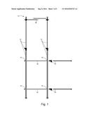
[0007] FIG. 1 is a diagram of a device according to an embodiment of the present disclosure, wherein each of the vertical and horizontal members are shown in two pieces with an adjustable coupling mechanism;
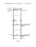
[0008] FIG. 2 is an annotated diagram of the device of FIG. 1;
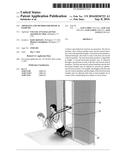
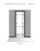
[0009] FIG. 3 is a diagram showing a device of the present disclosure mounted in a door frame;
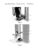
[0010] FIG. 4 depicts a portion of a device in use by an individual;
[0011] FIG. 5 depicts a portion of a device with assistance bands in use by an individual; and
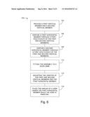
[0012] FIG. 6 is a chart showing a method according to another embodiment of the present disclosure.
DETAILED DESCRIPTION OF THE DISCLOSURE
[0013] With reference to FIG. 1, the present disclosure may be embodied as a device 10 for use by an individual to exercise the hamstring. By exercise, it should be understood that any conditioning or therapy, be it for strength, flexibility, rehabilitation or otherwise, is included. The device 10 is configured to be secured to the top 95 and lateral sides 90 of any door jambs without modification to the door frame (see, for example, FIG. 3). As such, the device 10 is adjustable as detailed below.
[0014] The device 10 comprises a first vertical member 12. The member 12 has an adjustable length in order to provide an interference fit with the upper jamb of the door opening 95 and threshold or floor surface 99. For example, the member 12 may be placed (at a shortened length) into the opening of a door frame in firm contact with the threshold or floor surface 99 and extended to contact the upper jamb at the top of the doorway 95. By placing the device 10 against the upper jamb and upper door stop, the member 12 will resist movement toward the user, meeting the jamb to provide stability. The first vertical member 12 may be adjustable in length by way of sliding the tubing with the smaller diameter into the vertical portion with the larger diameter, and by screwing the coupling pieces until the desired height of vertical member 12 is achieved, or in any other way. The adjustment may be lockable, for example, once the vertical sliding tubes of member 12 are adjusted in length and firmly in contact with upper jamb 95 and threshold or floor surface 99 in a desired position. The device 10 may further cooperate with door stops in order to prevent unintended removal from the door frame 90 while in use.
[0015] The device 10 comprises a second vertical member 14 which is configured similarly to the first vertical member 12. As such, the second vertical member 14 has an adjustable length in order to provide an interference fit secured between the threshold or floor surface 99 and upper jamb 95.
[0016] The device 10 further comprises a first horizontal member 20 configured to be removably disposed through a first hole 16 in each of the first and second vertical members 12,14, and wherein the first holes 16 are at a height h of the first and second vertical members 12,14 whereby the posterior ankles of the individual may be held near a floor by the first horizontal member 20 (for example, see FIGS. 4-5). In an exemplary embodiment, the height h is selected such that the ankles are held "near the floor" at a position which is less than a length of the user's foot. In another embodiment, the height his selected such that the toes or the balls of an average user's feet is are contact with the floor when the posterior ankles are in contact with the first horizontal member. In other embodiments, the height h may be more or less, as will be apparent to a person having skill in the art in light of the present disclosure. The first horizontal member 20 may alternatively be attached to the first and second vertical members 12,14 by, for example, welding, overlapping joints, etc.
[0017] The first horizontal member 20 may be configured to adjust in length in similar fashion to the vertical members 12,14. For example, the horizontal member 20 may have a coupling with a screw mechanism, concentrically arranged tubes, or otherwise. A coupling device may secure horizontal member 20 to both lateral jambs 90. Securing the horizontal members behind the door stop on the lateral jambs ensures stability and eliminates the possibility of displacement toward the user while using the device 10. A horizontal member 30 may attach similarly to provide maximum stability to device 10. In this way, the device 10 may be laterally stabilized such that movement will be resisted in the direction of the user. A horizontal member 40 may connect vertical members 12,14 to provide additional sites of band or tube attachment for assistance while performing the movement, and may utilize similar couplers to enhance stability.
[0018] The first and second vertical members 12,14 may have more than one hole for securing the first horizontal member 20 at various heights to accommodate individual anatomical differences and/or preferences. The device 10 may further comprise a foam pad 22 or other cushion for the individual's comfort (for example, see FIGS. 4-5). Each of the members 12,14,20,30 may have ends covered by caps to provide for non-marring contact with the upper jamb 95, lateral jamb 90 and threshold or floor surface 99.
[0019] The device 10 may further comprise a second horizontal member 30 configured to be removably disposed through secondary holes 18 in each of the first and second vertical members 12,14. The second holes 18 are at a height on the first and second vertical member 12,14 that is higher than the respective first holes 16. The second horizontal member 30 may be used for further securing the device 10 to the lateral jambs 90. By securing horizontal member positions against the lateral jambs 90 and door stops, forward displacement is prevented and stability is maximized. In addition, the device 10 may further comprise a third horizontal member 40 configured to be removably connected to each of the first and second vertical members 12,14. The attachment site may rely on a screw mechanism to the vertical members 12,14, and the length of the third horizontal member may be adjusted by sliding tubing to desired width or otherwise. Both the second horizontal member 30 and third horizontal member 40 may be used for attachment of assistance bands 32. The assistance bands 32 may be, for example, elastic bands or tubes, or any other such assistance devices as will be apparent in light of the present disclosure. In this way, the individual may have assistance in relieving some of the weight in lower/raising him or herself when using the device 10. The assistance bands 32 may also be attached and/or along the length of either vertical members 12,14 to provide lateralized assistance for the Nordic curl to compensate for asymmetrical or insufficient hamstring strength when using the device 10.
[0020] The assistance band 32 can be changed such to band(s) having a different resiliency such that differing levels of assistance (or no assistance) can be selected. The height position at which the assistance band(s) are attached to the device 10 may be selectable to provide differing assistance profiles. For example, where the assistance band 32 is attached at a low-to-mid height of the horizontal member 30 of the device 10, the assistance may be significantly lower at the start of the exercise. Alternatively, attaching the assistance band(s) 32 at a high position of the horizontal member 40 of the device 10 will provide assistance that is more directly related to the resistance of the assistance band(s) 32 themselves. These options allow for variable assistance depending on the range of the movement targeted by the user.
[0021] It should be noted that embodiments of a device according to the present disclosure may include additional horizontal and/or vertical members for increased stability or otherwise. For example, in an embodiment (see, for example, FIG. 3), the device 10 further comprises a first coupling sleeve 42 and a second coupling sleeve 44. Each of the first and second coupling sleeves 42,44 is configured to slide along a length of the corresponding first and second vertical members 12,14, respectively. A third horizontal member 40 spans from the first coupling sleeve 42 to the second coupling sleeve 44. Each of the first and second coupling sleeves 42,44 may further comprise a lock 43 for securing the respective coupling sleeve at a fixed vertical position of the corresponding vertical member. In this way, the assistance band(s) 32, or other components, may be attached to the third horizontal member 40 and located at adjustable heights. The horizontal and/or vertical members need not have a circular cross section, but may use square tubing, or any other configuration as will be apparent in light of the disclosure.
[0022] In another aspect of the present disclosure, a method 100 is provided. The method 100 comprises providing 103 a first vertical member and a second vertical member, each having an adjustable length. An assembly is formed by disposing 106 a first horizontal member through a first hole in each of the first and second vertical members. In some embodiments, the first horizontal member is removably disposed 106 through the first and second vertical members--in this way, the assembly may be disassembled for storage, transportation, etc. The first horizontal member is adjustable in length. In some embodiments, a second horizontal member is disposed 109 (for example, removably disposed) through a second hole in each of the first and second vertical members. The second horizontal member is adjustable in length.
[0023] The assembly is fit 112 into a door frame such that ends of each of the first and second vertical members and ends of the first horizontal member are in contact with door jambs of the door frame. By fitting 112 the assembly into the door frame, it is intended that the assembly be located at a position in the door frame, roughly co-planar with the door frame, and the lengths of the first and second vertical members and the first horizontal member are adjusted such that each end of each member is in contact with corresponding portions of the door jambs (see, e.g., FIG. 3). By locating each end of each of the first and second vertical members and the first horizontal member adjacent to (i.e., "behind"--see, e.g., FIG. 5) door stops of the door frame, the assembly cannot be pulled through the doorway (in a direction toward the door stops) due to the action of the door stops on the vertical and horizontal members. The lengths of each of the first and second vertical members and the first horizontal member may be adjusted 115 to provide an interference fit with to the door jambs.
[0024] The method 100 further comprises placing 118 the ankles of the user under the first horizontal member. The user is kneeling, and placing 118 the ankles under the first horizontal member provides that a posterior of the ankles contacts the first horizontal member and the first horizontal member limits vertical movement of the ankles. By contacting the first horizontal member, it is intended that the ankles are acted on by the first horizontal member to limit their vertical movement. For example, in some embodiments, the ankles may not be in direct contact with the first horizontal member; for example, a foam pad or other padding may be disposed between the ankles and the first horizontal member such that indirect contact is provided.
[0025] Although the present disclosure has been described with respect to one or more particular embodiments, it will be understood that other embodiments of the present disclosure may be made without departing from the spirit and scope of the present disclosure. Hence, the present disclosure is deemed limited only by the appended claims and the reasonable interpretation thereof.
User Contributions:
Comment about this patent or add new information about this topic:
Images included with this patent application:
 |  |
 |  |
 |  |
| Similar patent applications: | |
| Date | Title |
|---|---|
| 2016-10-06 | Synthesis of pure diallyl morpholinium monomers in high yields and using antibacterial effect of their spiro polymers |
| New patent applications in this class: | |
| Date | Title |
|---|---|
| 2022-09-22 | Electronic device |
| 2022-09-22 | Front-facing proximity detection using capacitive sensor |
| 2022-09-22 | Touch-control panel and touch-control display apparatus |
| 2022-09-22 | Sensing circuit with signal compensation |
| 2022-09-22 | Reduced-size interfaces for managing alerts |